Dacor Epicure EOG36 User manual

In s t a l l a t I o n In s t r u c t I o n s
Ep I c u r E ®ou t d o o r Gr I l l
For use with models EOG303, EOG36, EOG52, EOSB162
Part No. 65249 Rev. F

Appliance Safety ..........................................................................1
Important Safety Instructions .....................................................2
Design Specifications ..................................................................3
Product Dimensions....................................................................3
Installation Specifications ...........................................................4
Verifying The Package Contents ................................................4
Planning Installation Base Construction Structure .....................4
Installation Instructions..........................................................6-12
Accessory Doors.........................................................................6
Planning Installation Cart............................................................ 6
Assembly ....................................................................................6
Gas And Electrical Supply Requirements................................... 7
Electrical Supply Requirements.................................................. 7
Gas Supply Requirements.......................................................7-8
Gas Connections ........................................................................8
Connecting The Electrical........................................................8-9
Verifying Proper Operation .........................................................9
Electrical Schematics...........................................................10-11
Service Information....................................................................12
Ta b l e o f Co n T e n T s
What You Need to Know About Safety
Instructions
Warning and Important Safety Instructions appearing in this guide
are not meant to cover all possible conditions and situations that
may occur. Common sense, caution and care must be exercised
when installing, maintaining or operating appliance.
Always contact Dacor about problems or conditions you do not
understand.
Safety Symbols, Words, Labels
DANGER
DANGER – Immediate hazards which WILL result in severe
personal injury or death.
WARNING
WARNING – Hazards or unsafe practices which COULD result
in severe personal injury or death.
CAUTION
CAUTION – Hazards or unsafe practices which COULD result
in minor personal injury or property damage.
CALIFORNIA PROPOSITION 65 WARNING
The burning of gas cooking fuel generates some
by-products that are on the list of substances which
are known by the State of California to cause cancer or
reproductive harm. California law requires businesses
to warn customers of potential exposure to such
substances. To minimize exposure to these substances,
always operate this unit according to the use and care
manual, ensuring you provide good ventilation when
cooking with gas.
ap p l i a n C e sa f e T y
in s T a l l a T i o n Re C o m m e n d a T i o n s
The importance of the installation of the Dacor appliance cannot
be overemphasized. Installation should be done by a qualified
installer.
Before you begin the installation process, it is recommended that
you read this entire Installation Instruction Manual. There are key
details that you should take special care to observe during the
installation. By reading these instructions carefully, you will make
the installation process easier, problem-free and, most importantly,
safe.
Any questions or problems with the installation should be
directed to your Dacor dealer or the Dacor Customer Service
Department at (800) 793-0093. You can also visit our web site
at www.Dacor.com.

I
im p o R T a n T sa f e T y in s T R u C T i o n s
FOR YOUR SAFETY
If you smell gas:
1. Shut off gas to the appliance.
2. Extinguish any open flame.
3. Open lid.
4. If odor continues, immediately call your gas
supplier or your fire department.
FOR YOUR SAFETY
1. Do not store or use gasoline or other flammable
vapors and liquids in the vicinity of this or any
other appliance.
2. An LP cylinder not connected for use shall not
be stored in the vicinity of this or any other
appliance.
1. Read all instructions before using the appliance.
2. If the information in this manual is not followed
exactly, a fire or explosion may result causing
property damage, personal injury, or death.
3. Improper installation, adjustment, alteration,
service, or maintenance can cause personal injury
or property damage. Refer to these instructions
and the accompanying Use & Care manual. For
assistance or additional information, consult a
qualified installer, service agency, manufacturer
(dealer), or gas supplier.
4. This outdoor cooking gas appliance is not
intended to be installed in or on a recreational
vehicle and/or boats.
5. Do not obstruct the flow of combustion and
ventilation air.
6. Keep the ventilation openings for the LP cylinder
free and clear from debris.
7. Clean outdoor cooking appliances, including
special surfaces, with recommended cleaning
agents. Refer to the Use and Care manual
included with this appliance.
8. Check and clean the burner/venturi tubes for
insects and insect nests. A clogged tube can lead
to a fire beneath the grill.
9. Outdoor gas cooking appliances shall be used
only outdoors and shall not be used in a building,
garage, or any other enclosed area.
10. Do not install this appliance with surface
(downdraft) ventilation systems.
11. Do not install this appliance under unprotected
overhead combustible materials.
12. Disconnect the electrical supply before installing
or servicing this appliance.
13. This appliance must be grounded. Connect only to
a properly grounded electrical supply. Never use
an extension cord to operate this appliance.
14. Do not operate this appliance with a damaged
electrical cord or plug.
15. As with any appliance, close supervision is
necessary when used by children.
16. Installation of this appliance must be performed
by a qualified installer, service agency, or gas
supplier.
17. Excessive weight warning. Use two or more
people to move and install this product. Failure to
follow these instructions can cause injury.
18. This appliance should be serviced only by
qualified service personnel. Contact the nearest
Dacor authorized servicer at (800) 793-0093, or
at www.Dacor.com for examination, repair or
adjustment.
19. Keep outdoor cooking gas appliance areas clear
and free from combustible materials, gasoline and
other flammable vapors and liquids.
20. Inspect gas hose and regulator assemblies before
each use of the outdoor cooking gas appliance.
WARNING
WARNING
WARNING – NEVER use this appliance as a space heater
to heat or warm the room. Doing so may result in carbon
monoxide poisoning and overheating of the appliance.

2
Product Dimensions
de s i g n speCi f i C a T i o n s
3/8" (10mm)ø
Both sides
6" x 6" (152mm x 152mm)
Utility Cutout
25"
(635mm)
12" (305mm) Min.
to combustibles
above the countertop
surface 4 1/4"
(108mm)
21"
(533mm)
2" (51mm)
EOG30 - 21" (533mm)
EOG36/52 - 28" (711mm)
EOSB162 & EOG303/36/52
Cutout Dimensions Top View
9 1/8"
(232mm)
23"
(584mm)
26 3/8"
(670mm)
27 1/8"
(689mm)
30"
(762mm)
23"
(584mm)
EOG303 Overall Dimensions
9 1/8"
(232mm)
23"
(584mm)
26 3/8"
(670mm)
27 1/8"
(689mm)
36"
(914mm)
23"
(584mm)
EOG36 Overall Dimensions
8 3/4"
(222mm)
23"
(584mm)
26 3/8"
(670mm)
27 1/8"
(689mm)
16"
(406mm)
EOSB162 Overall Dimensions
8 3/4"
(222mm)
23"
(584mm)
26 3/8"
(670mm)
27 1/8"
(689mm)
52"
(1321mm)
23"
(584mm)
EOG52 Overall Dimensions

3
in s T a l l a T i o n speC i f i C a T i o n s
Verifying the Package Contents
EOG303/36/52 Models
• Grease Tray
• Grills
• Smoker Tray
• Rotisserie - forks - rod - motor
• Warming Rack
• Cleaning cream
• Regulator
• Light lens prystick
• Match Holder
• Even Heat Channels
EOG52 & EOSB162 Models
• Burner grate, caps, and cover
1. To reduce the risk of personal injury caused by
reaching over a hot appliance, cabinet storage
space located directly above the outdoor grill
should be avoided.
2. Do not store combustible materials or items
adversely affected by heat in cabinet areas around
the grill.
3. Failure to provide proper clearances as noted in
this installation instruction may result in a fire
hazard.
4. The back edge of the grill must maintain a
minimum clearance (8 inches/203mm) from
combustible back splash materials. This
will require special cabinet and countertop
dimensions.
5. Do not install the grill in a laminate, or synthetic,
solid surface countertop material.
6. This installation must conform local codes or,
in the absence of local codes, with either the
National Fuel Gas Code, ANSI Z223.1, or CAN/
CGA-B149.1, Natural Gas Installation Code, or
CAN/CGA-B149.2, Propane Installation Code.
7. Prevent grill combustion products from being
drawn into a building through fresh air inlets.
• Theventingsystemofotherthanadirect-vent
appliance shall terminate at least 4 feet (1.2m)
below, 4 feet (1.2m) horizontally from, or 1 foot
(305mm) above any door, window, or gravity
air inlet into any building. The bottom of the
vent terminal shall be located at least 12 inches
(305mm) above grade.
NOTES:
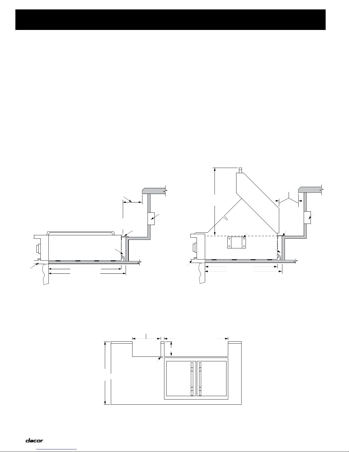
1. A MINIMUM clearance of 8 inches (203mm) must
be maintained, above the countertop material,
from all vertical materials constructed on the
sides or behind the outdoor grill chassis and
canopy. See detailed illustrations on page 3.
Planning Installation
Base Construction Structure
WARNINGS:
2. A MINIMUM clearance of 1/4 inch (6.4mm) must be
maintained, inside the base enclosure below the
countertop material, from all vertical surfaces on
the sides of the outdoor grill.
3. A MINIMUM clearance of 1 inch (25.4mm) must be
maintained, inside the base enclosure and below
the countertop material, from all vertical surfaces
behind the outdoor grill chassis.
4. Plan the installation so that the electrical
connection, gas shut-off valve, and pressure
regulator are accessible inside the base
enclosure.
5. All MINIMUM electrical and gas dimensions are
illustrated in the drawings within this manual.
Utility dimensions apply to all models unless
otherwise noted.
6. All models are designed to allow installation in
combustible or non-combustible base material
structures.
7. Locate the electrical supply box within reach
of the 48 Inch (1219mm) long power cord so
the connection is accessible when the grill is
completely installed in the enclosure.
8. For self contained LP-gas supply systems refer
to the detail in the Gas installation section of this
manual.
9. LP-gas cylinders should be ventilated by
openings at the level of the cylinder valve and the
floor level. The effectiveness of the openings, for
purposes of ventilation, shall be determined with
the LP-gas supply cylinder in place.
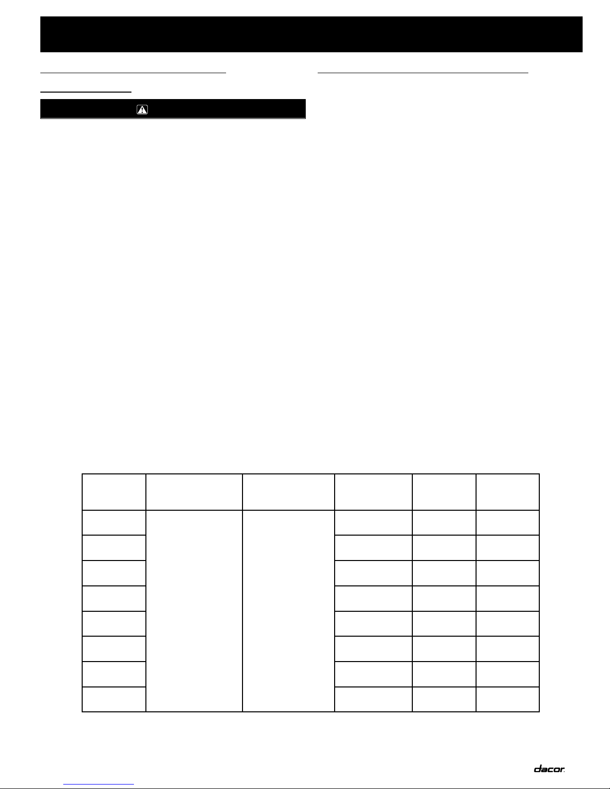
Plan to install the grill in a base structure that has one of the
following structural details:
1. One side of the base structure enclosure completely open.
2. For an enclosure having four sides, a top, and bottom:
• At least two ventilation openings at cylinder valve level shall be
provided in the side wall, equally sized, spaced at 180 degrees
and unobstructed.
• Each opening shall have a total free area of not less than 10
square inches (254 square mm).
• Ventilation openings shall be provided at floor level and shall
have a total free area of not less than 10 square inches (254
square mm). If the ventilation openings at floor level are in a
side wall, there shall be at least two openings. The bottom of
the openings shall be at floor level and the upper edge no more
than 5 inches (127mm) above the floor. The openings shall be
equally sized, spaced, and unobstructed.
The LP cylinder valve shall be readily accessible for hand
operation. A door on the enclosure to gain access to the cylinder
valves is acceptable, provided it is non-locking and can be
opened without the use of tools.
The enclosure for the LP-gas cylinder shall isolate the cylinder
from the burner compartment to provide shielding from radiation,
a flame barrier, and protection from foreign materials such as hot
drippings.
There shall be a minimum clearance of 2 inches (51mm) between
the floor of the LP-gas cylinder enclosure and the ground.
The design of the outdoor cooking enclosure must allow the LP-
gas cylinder to be connected, disconnected and the connections
inspected and tested outside the cylinder enclosure.

4
in s T a l l a T i o n speC i f i C a T i o n s
Connections, which may be disturbed when installing the cylinder
in the enclosure can be leak tested inside the enclosure.
Internal mounting means shall be provided on the outdoor gas grill
for mounting the LP-gas supply cylinder. If the outdoor grill is not
in use, the gas must be turned off at the supply cylinder.
Storage of an outdoor grill is permissible only if the cylinder is
disconnected and removed from the outdoor cooking appliance.
Optional Finish Trim (Model AOGT)
An optional finish trim can be installed on the countertop to finish
the sides and back of the countertop opening. The stainless
steel finish trim can be caulked to the countertop and should be
secured to the base enclosure with flat head decking screws
(supplied by others). Center the trim within the cutout dimensions
noted in this manual, then utilizing the deck screws and holes
located along the vertical sides of the finish trim install them
securely to the base enclosure countertop sub-straight. Install the
trim before installing the grill.
NOTE:
The rotisserie mounting bracket on the right side
of the grill chassis and the slot in the right side
finish trim must line up for proper rotisserie motor
installation. (Selected models only)
Junction
Box
Trim frame
(accessory)
3/4" (19mm)
Min. to any
material
8" (203mm) Min. to combustibles
2" (51mm) Min. to non-combustible
1"
(25mm)
23" (584mm)
24" (610mm)
EOSB162 Cutout Dimensions
Side View
Rotisserie mounting
bracket (factory installed)
Junction
Box
Trim frame
(accessory)
3/4" (19mm)
Min. to any
material
8" (203mm)
Min. to
combustibles
2" (51mm)
Min. to
non-combustible
1"
(25mm)
23" (584mm)
24" (610mm)
28" (711mm)
To finished
countertop
EOG303/36/52 Cutout Dimensions
Side View
3/4" (19mm)
Min. to any
material
8" (203mm) Max.
36"
(914mm)
EOG30 - 30 1/2 (775mm)
EOG36 - 36 1/2" (927mm)
EOG52 - 52 1/2" (1334mm)
EOS16
16 1/8" (410mm)
EOSB162 & EOG303/36/52 Cutout Dimensions
Front View
(AGAD 36” Accessory Door shown)

5
in s T a l l a T i o n speC i f i C a T i o n s
Gas and Electrical Supply
Requirements
WARNING
Electrical grounding instructions:
This outdoor cooking gas appliance is equipped with
a three-prong grounding plug for your protection
against shock hazard and should be plugged into a
properly grounded three-prong receptacle. Do not
cut or remove the grounding prong from the plug.
NOTES:
1. If the gas or electric service provided does not
meet the product specifications, do not proceed
with the installation.
2. The grounding plug must not, under any
circumstances, be cut or removed.
3. Check your local codes for proper method
of installation. In absence of local code, this
appliance should be installed in accordance with
the National Fuel Gas Code ANSI Z223.1. Or CAN/
CGA-B149.1, Natural Gas Installation Code or
CAN/CGA-B149.2, Propane Installation Code.
4. Be certain that the appliance being installed is
correct for the gas service being provided.
5. This appliance must be installed by a licensed
plumber or gas fitter when installed within the
Commonwealth of Massachusetts.
Electrical Supply Requirements
Electrical and Gas Supply Requirements
Table 1
Model No.
Electrical circuit
required
Total connected
load Gas type
Manifold
Pressure
Min. Gas
Supply
Pressure
EOG303
120VAC, 60HZ, 15A 2.9 Amps (0.35kW)
Natural 4” Water
Column
7” Water
Column
EOG303LP Liquid Propane 11” Water
Column
12” Water
Column
EOG36 Natural 4” Water
Column
7” Water
Column
EOG36LP Liquid Propane 11” Water
Column
12” Water
Column
EOG52 Natural 4” Water
Column
7” Water
Column
EOG52LP Liquid Propane 11” Water
Column
12” Water
Column
EOSB162 Natural 4” Water
Column
7” Water
Column
EOSB162LP Liquid Propane 11” Water
Column
12” Water
Column
The EOG outdoor grills are factory-equipped with a three-prong,
grounding plug.
Correct voltage, frequency and amperage must be supplied to the
appliance from an isolated, grounded circuit which is protected by
a properly sized circuit breaker or time-delay fuse. The required
voltage, frequency, and amperage ratings are listed on the
product data plate and are also shown in Table 1, see below.
These outdoor grills must be connected to a power source
with copper wire only. The use of aluminum wire may result in
unsatisfactory connections.
It is the owner’s responsibility to ensure that the electrical
connection to this appliance is installed by a qualified electrician.
The electrical installation, including minimum supply wire size
and grounding, must be done in accordance with National
Electric Code ANSI/NPFA 70, (or the latest revision) or
Canadian Electrical Code CAN/CGA C22.1, and local codes and
ordinances.
Total connected loads noted above include the ignition system,
interior lights, and rotisserie motor. Rotisserie motor should be
plugged into the same grounded outlet power source on the same
line as the grill.
Install 120VAC, 15 Amp duplex outlet in an accessible location
under the grill inside the base enclosure. Refer to Base Enclosure
planning cutout dimensions for recommended utilities locations.
NOTE:
Supply access for the rotisserie power or an alternate
120VAC duplex outlet location.

6
1. The maximum gas supply pressure to the
regulator must not exceed 1/2 pound per square
inch.
2. Verify proper gas supply has been provided. Refer
to Tabe 1, Page 6.
3. Do not apply excessive pressure when tightening
connections and fittings.
4. Do not use plumber’s putty or Teflon tape on gas
compression connections. It can defeat the proper
sealing of these fittings. Use plumber’s putty or
Teflon tape only on pipe thread fittings.
5. Turn all outdoor grill control valves to the “OFF”
position, then turn on the gas supply. Check all
supply lines and connections for leaks using a
soap and water solution. Do not use a flame to
check leaks. After verifying that there are no gas
leaks, turn off the gas supply to the grill by turning
the gas shut-off valve to the “OFF” position.
Leak testing of the appliance shall be conducted
according to the manufacturer’s instructions.
6. For LP cylinder installations, the LP gas cylinder
must have its own Certified high-pressure
regulator (Either Type I or No. 600 Connection).
7. Natural gas installations will be connected to
factory supplied natural gas regulator. Refer to
Natural gas connections in this manual for details.
8. Inspect the gas line before and after installation.
Also, inspect the line for damage before each use
of the outdoor grill.
Gas Supply Requirements
WARNING
in s T a l l a T i o n speC i f i C a T i o n s
NOTES:
1. No adjustment of burner settings is required.
All valves and air mixture shutters found in this
appliance have been factory preset.
2. Liquid propane (LP) grills should be special
ordered from the factory. Liquid propane units are
identified by the “LP” designation at the end of
the model number on the product identification
chassis tag.
3. Under extenuating circumstances, outdoor grills
may be field converted to operate on LP gas or at
elevations in excess of 5,000 feet above sea level.
However, field conversion must be completed
by a qualified service agency and authorization
must be granted by the factory prior to any field
conversion.
4. To prevent damage to the gas regulator, install
the regulator only after the grill is mounted in
its permanent position in the enclosure or cart.
Ensure the arrow on the regulator points in the
direction of the gas flow towards the grill.

7
in s T a l l a T i o n in s T R u C T i o n s
Accessory Doors
Accessory Doors Specifications
IMPORTANT:
1. Excessive weight warning - Both the cart and
the grill are extremely heavy and this installation
assembly process should be accomplished by a
minimum of two people.
2. Sheet metal edges can be dangerous in heavy
lifting situations, please wear gloves during
assembly.
3. To lighten the grill before assembly, remove
individual components box packed inside the grill.
4. Remove the cart from the shipping pallet before
installation assembly.
NOTES:
1. The Dacor cart ships assembled ready for the
EOG Outdoor Grill installation assembly.
2. All gas and electrical connections should be made
after the grill is installed and bolted to the cart.
Specifications Measurements
Overall Width AGAD20 - 19 1/2” (495mm)
AGAD36 - 35 7/8” (911mm)
Overall Height 21” (533mm)
Overall Depth 1/4” (6mm) deep return on frame edge
Cutout Width AGAD20 - 16 3/4” (425mm)
AGAD39 - 33 1/8” (841mm)
Cutout Height 18 3/4” (476mm)
Cutout Depth 3” (76mm) Minimum
3. Your cart is prepared for either natural gas or
liquid propane gas connections. However, it is
important to verify that your EOG was ordered
correctly. If you will be utilizing LP gas, your
EOG grill must indicate LP in the serial tag
identification. Do not proceed with assembly if the
EOG model is not correct. Field conversion from
one gas type to another is not recommended by
Dacor.
1. Remove the cart from the shipping carton and pallet.
2. Set the cart in an open location and lock the wheel on the
cart to minimize potential movement. Remove the right side
roll out tank drawer.
3. Loosen the two fasteners, located in the front right corner
behind the horizontal support, temporarily creating a 1/2” gap
between the support rail and right side panel.
4. Remove the EOG from its shipping carton and pallet.
Remember to remove the individual components box to
lighten the appliance.
5. Slide the EOG into the cart making sure that it is all the
way back in the opening as far as possible. At this point the
mounting holes under the bottom of the EOG should align
with the holes in the cart supports.
6. Tighten the two fasteners that were loosened in step 3 before
securing the EOG to the cart.
7. Prepare to secure the EOG to the cart by removing the left
drawer. Once this is out of your way locate the two assembly
bolts which are inside the EOG parts package.
8. Install the bolts, then return the left side drawer to its location.
9. Before installing the right side roll out tank drawer, Install
the regulator and hose on the grill drawer for final gas
connection.
10. Proceed to steps 4 and 5 in the EOG installation instructions
for the appropriate gas and electrical connections and step 6
to verify proper operation.
11. Install the right side slide out tank shelf.
12. Five gallon LP tanks are the largest
recommended tank for installation in the
rollout tank drawer.
NOTE:
Dacor offers a protective grill or grill/
cart cover. For more information
concerning these covers contact
your Dacor appliance dealer.
Planning Installation Cart
Lift up work
Surface Fixed
wheels
Loosen
Fasteners
1/2" Gap before install
Roll out storage
Drawers (2)
Roll out
LP tank
drawer
Gas and
Electrical
Locking
wheel
Lift up work
Surface
Assembly
Shown: OGC36 and EOG36
Length: 41 3/8” (1051mm), Height: 36” (914mm), Width: 26 1/4” (667mm)
Not Shown: OGC52 and EOG52
Length: 57” (1448mm), Height: 36” (914mm), Width: 26 1/4” (667mm)

8
In s t a l l a t I o n In s t r u c t I o n s
Gas Connections
WARNINGS:
Natural Gas Connections
Verify gas supply pressures are acceptable based on the table on
page 6.
The Dacor outdoor cooking products ship with a 3/4 inch nipple,
regulator, and 1/2” reducer for gas supply connections.
Install a 3/4 inch (19mm) or 1/2 inch (13mm) natural gas supply
line, with a shut off valve (not included with the outdoor product),
in an accessible location under the appliance. Place the gas
supply line and shut off valve inside the base enclosure within a
reachable distance from the front access doors or open rear area
of the enclosure. Refer to base enclosure planning and cutout
dimensions page within this manual for additional detail.
.
Connect the, factory supplied, regulator and gas line nipple at the
back right bottom corner of the grill. Use only approved gas line
thread compound, regulators, and gas hose. Be certain the gas
flow arrow on the regulator is installed with the flow in the correct
direction.
Install approved flexible gas line from the regulator to the rough
gas line shut off valve using the factory supplied regulator.
Check all gas connections for leaking by applying a water and
soap solution. If you observe leakage (soap bubbles around any
connections) do not attempt to operate the grill without correcting
the leak.
Liquid Propane (LP) Connections
1. A dented or rusty LP tank may be hazardous and
should be checked by your LP supplier.
2. Never use a cylinder with a damaged valve.
3. A Portable Liquid Propane tank should be a 5
gallon, 20 lb. gas cylinder approximately 12 inches
(305mm) in diameter and 18 inches (457mm)
high, which must be constructed and marked
in accordance with the specification for Liquid
Propane (LP) gas cylinders of the U.S. Department
of Transportation (DOT) and designed for use with
a 5LP-A quick disconnect systems only.
4. Do not change the regulator/hose assembly with a
standard 510 POL tank/valve assembly.
5. The cylinder must be provided with a shut-
off valve terminating in a Liquid Propane (LP)
gas supply cylinder valve outlet specified, as
applicable, for connection No. 5LP-A.
6. The cylinder supply system must be arranged
for vapor withdrawal and provided with a listed
overfilling prevention device.
7. If the appliance is stored indoors, the cylinder
must be disconnected and removed from the
appliance.
8. Cylinders must be stored outdoors in a well
vented area out of the reach of children.
Make sure the LP tank main valve is completely closed before
proceeding with the installation.
1. In the event of a power failure. Use Dacor supplied
match lite tool.
2. Verify that the proper electrical power supply has
been provided.
3. Verify that the electrical supply matches the
ratings found on the appliance data plate before
proceeding.
4. This appliance must be connected to a grounded,
metallic, permanent wiring system. Alternatively,
a grounding conductor should be connected to
the grounding terminal or lead on the appliance.
Failure to do so may result in an electrical shock
hazard.
5. Do not use an extension cord with this appliance.
Such use may result in fire, electrical shock, or
other personal injury.
6. Do not install a fuse in the neutral or ground
circuit. A fuse in the neutral or ground circuit may
result in an electrical shock hazard.
7. Do not ground this appliance to a gas supply pipe
or hot water pipe.
8. Keep any electrical supply cord and the fuel
supply hose away from any heated surfaces.
Plug the factory supplied, three-prong plug located at the bottom
back right corner of the grill into the grounded receptacle.
Also, install the rotisserie motor and spit at this time (Use and
Care instruction for proper rotisserie installation) be sure to plug
only into a grounded receptacle.
Connecting the Electrical
WARNINGS:
Install the LP regulator and gas hose on the grill main gas stub at
the right rear corner of the appliance. Follow all regulator and gas
line instructions as noted in the warnings above.
Place the tank into the final position within the base enclosure or
cart.
NOTE:
The Dacor outdoor grills are approved for installation
on typical whole-house LP gas supply systems. For
proper whole-house LP gas installation order Dacor
part # 72601.
Three-Prong Plug
Three-prong grounded receptacle
and cover plate
Three-Prong Plug and Receptacle

9
In s t a l l a t I o n In s t r u c t I o n s
1. If the grill or cooktop fails to operate properly,
ensure that the electrical power supply and gas
supply are turned on and that all installation steps
have been carefully followed. Call a qualified
service technician if the grill still does not operate
properly.
2. The grill or cooktop and shut-off valve must be
disconnected from the gas supply piping during
any pressure testing exceeding 1/2 psi (3.5kPA).
3. The grill or cooktop must be isolated from the gas
supply piping by closing the shut-off valve during
any pressure testing at or below 1/2 psi (3.5kPA).
4. The top cover (canopy) is to be closed during the
outdoor cooking gas appliance pre-heat period.
5. Visually check the burner flame for carry over and
proper operation.
6. Proper flame operation will show a soft blue color
and stable flame.
7. Remove side burner cover before operating side
burners.
8. Never place the cover over operating side
burners.
9. Remove all shipping material from around side
burners and side burner cover before operating
side burners.
Lighting Instructions for Grills or Cooktops (Liquid Propane)
Turn ON the main tank valve, then turn all burners ON to the
high position for approximately 20 seconds to allow the air in the
system to purge from the grill and cooktop side burners.
Once the gas has filled the lines the automatic electronic ignition
system should ignite the burner. If the system burners do not
ignite within 20 seconds turn all burner controls to the OFF
position and wait five minutes and attempt the ignition process
again.
If the second or third attempt to ignite the burner is not successful
then turn all burner controls to the OFF position. Turn off the
main gas line control valve or LP tank control valve and contract
your authorized Dacor service agent to schedule a service call.
When installed properly, the flame will be steady and quiet.
Flame adjustment will not be necessary, all grill and side burners
are factory adjusted, for proper performance.
Read and understand the accompanying use and care manual
prior to cooking with this appliance. The use and care manual
contains additional important safely, service and warranty
information.
Specifications contained within are subject to change without
notice. No liability is assumed for changes in specifications.
Light & high position Off position
Low position
Burner indicator light
Gas Control Knob
Verifying Proper Operation
WARNINGS:

10
in s T a l l a T i o n in s T R u C T i o n s
Electrical Schematics
GN
W
BK
PLUGS
IGNITION
4 POINT
RE-IGNITER
S2S4 S3 S1
GN
N
A 34
S4
S3
2 1
S2
LIGHTS
INDICATOR
W
BK
BK
PLUG
TERMINAL BLOCK
N
L1 BK
W
BK
BK
GN
W
W
FOR OUTDOOR USE
SUPPLY CORD & STRAIN RELIEF
3-PRONG
10
12 3 5
W
SECONDARY 12VAC
DUAL PRIMARY
120VAC INPUT EACH
INFRARED
BURNER
LEFT
GRILL
BURNER
RIGHT
GRILL
BURNER
W
BK BK BK
W
W
BK BK BK
BK BK BK
W
BK
O
BK BK
W
BK
BK
W
WBR
HALOGEN LIGHT
SWITCH
LEFT HALOGEN LIGHT
10W, 12V
BR BR
BK BK
BK
BK
BK
W
GN SUPPLY CORD & STRAIN RELIEF
FOR OUTDOOR USE
BK W
PLUG
3-PRONG
BK
BK W GN
BKBK W
GN
ROTISSERIE
SWITCH
CCW ROTATION
ROTISSERIE BOX DIAGRAM
60 Hz
120VAC, 0.65A
2VA, 120VAC 60Hz
HALOGEN LIGHTS
TRANSFORMER
BR
10W, 12V
RIGHT HALOGEN LIGHT
BR
BR
W
BK RED
RED
EOG303 Electrical Schematic
GN
W
BK
PLUGS
IGNITION
4 POINT
RE-IGNITOR
S2
S4 S3 S1
GN
N
A3
4
S4
S3
2 1
S2
S1
LIGHTS
INDICATOR
W
BK BK
PLUG
TERMINAL BLOCK
N
L1 BK
W
BK
BK
GN
W
W
FOR OUTDOOR USE
SUPPLY CORD & STRAIN RELIEF
3-PRONG
INFARED
BURNER
LEFT
GRILL
BURNER
CENTER
GRILL
BURNER
RIGHT
GRILL
BURNER
W
BK BK BK BK
WW
BK BK BK BK
BK BK BK
BK
W
BK
O
BK BK
BK
W
BK BK BK
BK
BK BK
BK
GN SUPPLY CORD & STRAIN RELIEF
FOR OUTDOOR USE
BK W
PLUG
3-PRONG
BK
BK W GN
BKBK W
GN
ROTISSERIE
SWITCH
CCW ROTATION
ROTISSERIE BOX DIAGRAM
60 Hz
120VAC, 0.65A
2VA, 120VAC
60Hz
TRANSFORMER
HALOGEN LIGHTS
BK
120VAC INPUT EACH
DUAL PRIMARY
12VAC
SECONDARY
W
532
1
10
6
RED
REDBK
WBR
BR
RIGHT HALOGEN LIGHT
10W, 12V
BRBRBR
10W, 12V
LEFT HALOGEN LIGHT
SWITCH
HALOGEN LIGHT
BR
W
EOG36 Electrical Schematic

11
in s T a l l a T i o n in s T R u C T i o n s
GN
W
BK
PLUGS
IGNITION
PLUG
TERMINAL BLOCK
N
L1 BK
W
BK
BK
GN
W
W
FOR OUTDOOR USE
SUPPLY CORD & STRAIN RELIEF
3-PRONG
GN SUPPLY CORD & STRAIN RELIEF
FOR OUTDOOR USE
BK W
PLUG
3-PRONG
BK
BK W GN
BKBK W
GN
ROTISSERIE
SWITCH
CCW ROTATION
ROTISSERIE BOX DIAGRAM
120VAC, 0.65A, 60Hz
6 POINT RE-IGNITER
120VAC, 2VA, 60Hz
S6 S4S5 S3 S1
S2
N
A4
5
63 2 1
BK
BURNER
FRONT SIDE
BK
BURNER
REAR SIDE
BK
BURNER
LEFT GRILL
BK
CENTER
GRILL
BURNER
BK
RIGHT
GRILL
BURNER
BK
O
BK
BK
BK BK
S2
BK BK
W
S1
W
BK BK
W
BK
BK BK
S3
S4
S5
GN
W
W
BK
BK
BK
BK BK
S6
BK
BKBKBKBK
W
W
W
BURNER
INFRARED
W
INDICATOR
LIGHTS
BKBKBKBKBK BK
TRANSFORMER
HALOGEN LIGHTS
BK
120VAC INPUT EACH
DUAL PRIMARY
12VAC
SECONDARY
W
532
1
10
6
RED
REDBK
WBR
BR
RIGHT HALOGEN LIGHT
10W, 12V
BRBRBR
10W, 12V
LEFT HALOGEN LIGHT
SWITCH
HALOGEN LIGHT
BR
W
EOG56 Electrical Schematic
Electrical Ratings
120VAC, 60Hz
Unit: 1.9A
Rotisserie: 1.0A
Total Connected Load: 2.9A
Electrical Ratings

12
se R v i C e in f o R m a T i o n
If you need service, be sure to have the model and serial numbers
when you call. You’ll find these numbers on the serial number
plate located on the light shield in the fresh food compartment.
Contact a Dacor authorized servicer, a Dacor dealer, or the Dacor
Customer Service Department at (800) 793-0093.


The information and images in this book are the copyright
property of Distinctive Appliances, Inc. Neither this book nor any
information or images contained herein may be copied or used
in whole or in part without the express written permission of
Distinctive Appliances, Inc.
© 2006 Distinctive Appliances, Inc. all rights reserved.
Specifications contained within are subject to change without notice.
No liability is assumed by DACOR for changes in specifications.
Web site: www.Dacor.com
Phone: (800) 793-0093
Other manuals for Epicure EOG36
1
This manual suits for next models
1
Table of contents
Other Dacor Grill manuals

Dacor
Dacor EOG303 User manual

Dacor
Dacor Epicure OB36 User manual

Dacor
Dacor Epicure 0B36 User manual

Dacor
Dacor EG366 User manual

Dacor
Dacor Epicure OB36 User manual

Dacor
Dacor AEGR30 User manual

Dacor
Dacor Epicure OBS36 User manual

Dacor
Dacor EOG303 User manual

Dacor
Dacor Epicure OB36 User manual

Dacor
Dacor Discovery OB36 User manual