1. Specifications -------------------------------------------------------------
1
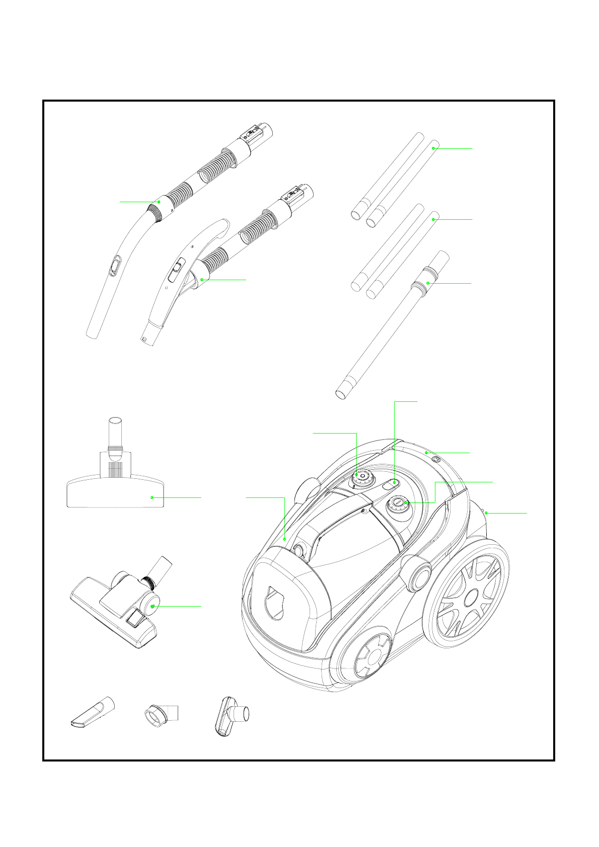
2. External Views ------------------------------------------------------------
2
2-1. External Components List ---------------------------------------------------
2
2-2. External Components View -------------------------------------------------
3
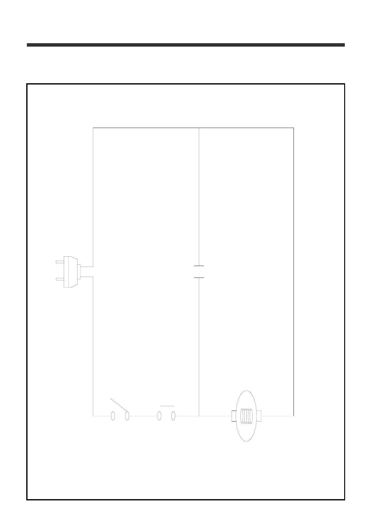
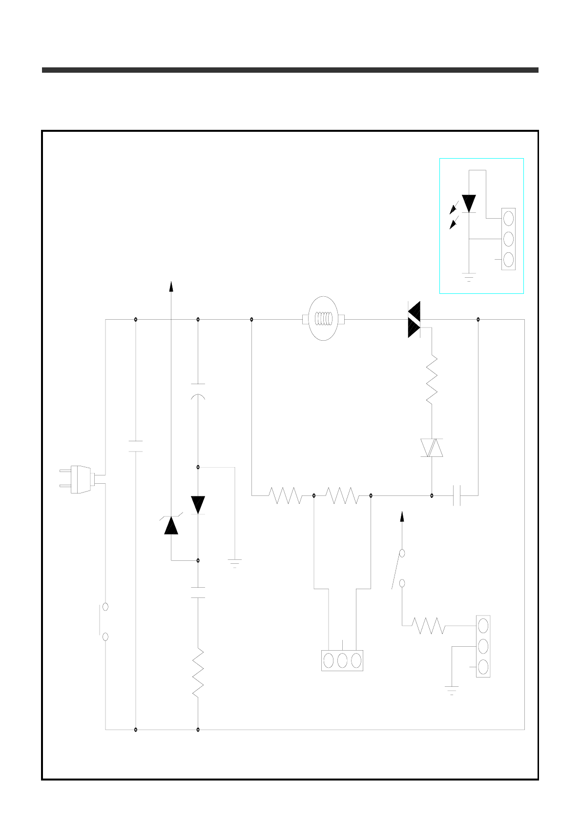
3. Electrical Description (Diagram) ------------------------------------ 4
3-1. Wiring Diagram ----------------------------------------------------------------
4
3-2. Circuit Diagram ----------------------------------------------------------------
6
4. Trouble Shooting Guide -----------------------------------------------
9
5. Disassembling and Treatment --------------------------------------
11
5-1. Cleaner Assembly -------------------------------------------------------------
11
5-2. Motor Assembly ---------------------------------------------------------------- 12
5-3. Cordreel Assembly ------------------------------------------------------------
13
5-4. Cover Assembly ---------------------------------------------------------------
15
5-5. Hose Assembly ----------------------------------------------------------------
16
5-6. Brush Assembly ---------------------------------------------------------------
17
6. Exploded View and Part List -----------------------------------------
18
6-1. Cleaner Assembly -------------------------------------------------------------
18
6-2. Body Assembly ----------------------------------------------------------------
24
6-3. Cover Assembly ---------------------------------------------------------------
28
6-4. Cover Top Assembly ---------------------------------------------------------
34
6-5. Motor Case Assembly --------------------------------------------------------
37
6-6. Cordreel Assembly ------------------------------------------------------------
39
6-7. Cover Side Assembly --------------------------------------------------------
41
6-8. Dustbox Assembly ------------------------------------------------------------
42
6-9. Hose Assembly ----------------------------------------------------------------
46
6-10. Pipe Assembly ---------------------------------------------------------------- 50
6-11. Brush Assembly --------------------------------------------------------------
51
Page
Table of Contents