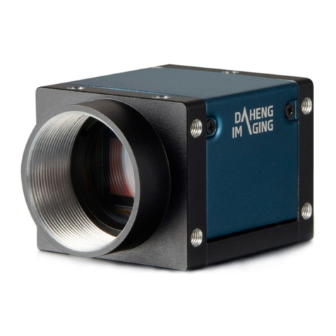
Daheng Imaging VEN-134-90U3M-D User manual

VEN-134-90U3M-D Board Level Cameras
User Manual
Version: V1.0.2
Date: 2019-07-09
China Daheng Group, Inc. Beijing Image Vision Technology Branch

Notice
All rights reserved. No parts of this manual may be used or reproduced, in any forms or by any means,
without prior written permission of China Daheng Group, Inc. Beijing Image Vision Technology Branch.
The right is also reserved to modify or change any parts of this manual in the future without prior notification.
All other trademarks are the properties of their respective owners.
© 2019 China Daheng Group, Inc. Beijing Image Vision Technology Branch
Web:
http://www.daheng-imaging.com/en
Sales Email:
isales@daheng-imaging.com
Sales Tel:
+86 10 8282 8878
Support Email:
isupport@daheng-imaging.com

Preface
We really appreciate you choosing the product of DAHENG IMAGING.
VEN-134-90U3M-D board level camera is DAHENG IMAGING’s CMOS board level binocular camera,
featuring small size, flexible assembly, high definition and extremely low noise. The camera, which is
equipped with a standard USB3.0 Micro-B interface, is easy to install and use. It could be used in a wide
and diverse range of applications including industrial inspection, medical imaging, scientific research,
education and other fields.
VEN-134-90U3M-D board level camera is small in size, supports binocular acquisition, and a variety of
front-end data transmission cables (FPC) with optional length are available, which will be a good choice
for users with board level binocular needs. Please read this manual carefully before using the VEN-134-
90U3M-D board level camera.

© China Daheng Group, Inc. Beijing Image Vision Technology Branch I
Contents
1. Introduction......................................................................................................................1
1.1. General Specifications ............................................................................................ 1
1.2. Spectral Response.................................................................................................. 2
1.3. Mechanical Interface ............................................................................................... 2
1.3.1. Acquisition Board Mechanical Dimensions .........................................................................2
1.3.2. Imaging Board Mechanical Dimensions..............................................................................3
1.4. Software Interface ................................................................................................... 3
1.4.1. User Software Package.......................................................................................................3
1.4.2. Application Programming Interface .....................................................................................4
1.5. Guideline for Avoiding EMI/ESD.............................................................................. 5
1.6. Environmental Requirements.................................................................................. 6
1.7. Standards and Regulations: CE, ROHS.................................................................. 6
2. Electrical Interface...........................................................................................................7
2.1. USB3 Port ............................................................................................................... 7
2.2. IO Port..................................................................................................................... 7
2.2.1. Line2/Line3 (bidirectional) Circuit........................................................................................8
2.2.2. Line2/3 configured as input.................................................................................................8
2.2.3. Line2/3 configured as output...............................................................................................9
3. Installation and Use.......................................................................................................11
3.1. Hardware Installation..............................................................................................11
3.2. Software Installation.............................................................................................. 13
4. FAQ.................................................................................................................................14
5. Revision History ............................................................................................................15

1. Introduction
© China Daheng Group, Inc. Beijing Image Vision Technology Branch 1
1. Introduction
1.1. General Specifications
Specifications
VEN-134-90U3M-D
Resolution
1280 ×1024 ×2
Sensor Type
Onsemi PYTHON 1300, Global shutter CMOS
Optical Size
1/2 inch
Pixel Size
4.8μm × 4.8μm
Frame Rate
90fps @ 1280 ×1024 ×2
ADC Bit Depth
10bit
Pixel Bit Depth
8bit, 10bit
Shutter Time
5μs~1s
Gain
0dB~16dB
Pixel Data Formats
Mono 8/ Mono10
Signal to Noise Ratio
39dB
Definition
>951 lines
Synchronization
External trigger, Software trigger
I/O
2 GPIOs
Operating Temp.
0°C~45°C
Storage Temp.
-20°C~70°C
Operating Humidity
10%~80%
Power Consumption
<3.5W@5V
Data Interface
USB3.0
Regulations
CE, RoHS, USB3.0 Vision, GenICam
Table 1-1: VEN-134-90U3M-D general specifications

1. Introduction
© China Daheng Group, Inc. Beijing Image Vision Technology Branch 2
1.2. Spectral Response
Figure 1-1: VEN-134-90U3M-D spectral response
1.3. Mechanical Interface
1.3.1. Acquisition Board Mechanical Dimensions
The following figure is the size of the acquisition board (units: mm).
4-φ2.2 is used for PCB board fixation. The maximum height of the top side (outside the screen) of the PCB
board is 3, the maximum height of the bottom (in the screen) of the PCB board is 1.8.
Figure 1-2: Acquisition board mechanical dimensions

1. Introduction
© China Daheng Group, Inc. Beijing Image Vision Technology Branch 3
1.3.2. Imaging Board Mechanical Dimensions
The following figure is the size of the imaging board (units: mm).
4-φ2.2 is used for PCB board fixation. The maximum height of the top side (outside the screen) of the PCB
board is 2.4, the maximum height of the bottom (in the screen) of the PCB board is 3.7.
2-φ2.1 is the positioning hole for the installation and location of the optical center of the image sensor.
Figure 1-3: Imaging board mechanical dimensions
1.4. Software Interface
1.4.1. User Software Package
The Software package of DAHENG IMAGING is used to control the VEN series camera, is to provide a
stable, real-time image transmission, and provides an easy-to-integrate SDK and abundant development
example source codes. The package is composed of the following modules:
1) Driver Package (Driver): This package provides the VEN series camera driver program, such as: the
USB3.0 cameras’ driver program.
2) Application Program Interface (API): This package provides the camera control application program
interface library and the image processing interface library, supports the user for secondary
development.
3) Demonstration Program (GalaxyView.exe): This demonstration program is used to display the camera
control, image acquisition and image processing functions, the user can control the camera directly by

1. Introduction
© China Daheng Group, Inc. Beijing Image Vision Technology Branch 4
the demonstration program, and also the user can develop their own control program based on the
camera interface library.
4) Sample: The sample demonstrates the camera functions, the user can easily use these samples to
control cameras, and also can refer to the samples to develop their own control program.
5) Programmer’s Manual: This manual is the users programming guide that instructs the users how to
configure the programming environment and how to control camera and acquisition images through
the camera interface library.
You can download the latest camera package from the website: www.daheng-imaging.com/en/
Downloads/ Software Downloads.
1.4.2. Application Programming Interface
After installing the software package, the user can use the demonstration program and the samples to
control the camera, also the user can control the camera by the program which is written by the user
themselves. The software package provides three kinds of program interfaces, the user can select the
suitable one for use according to their own requirements:
1) API Interface
In order to simplify the users’programming complexity, the package provides the general C programming
interface GxIAPI and image processing algorithm interface DxImageProc for the user to control the camera,
and also provides the samples and software development manuals which are based on these interfaces.
2) GenTL Interface
This interface is developed according to the standard of general transport layer in Gen<i>Cam standard,
Daheng follows the Gen<i>Cam standard and provides the GenTL interface for the user, the user can use
the GenTL interface directly to develop their own control program. The definition and usage of GenTL
interfaces can be downloaded from the website of EMVA.
In addition, users can use some third-party software that supports Gen<i>Cam standard to control the
camera, such as HALCON.
3) USB3.0 Vision Interface
The VEN series USB3.0 camera is compatible with the USB3.0 Vision protocol, which allows the user to
control the camera directly through the USB3.0 Vision protocol. In addition, the user can use some third-
party software that supports the USB3.0 Vision protocol to control the camera, such as HALCON.
Note:
GEN<i>CAM standard: GEN<i>CAM is administered by the European Machine VisionAssociation (EMVA).
GenICam provides a generic programming interface for all kinds of cameras and devices. It provides a
standard application programming interface (API), no matter what interface technology is being used. It
mainly includes the following modules:
GenAPI: an XML description file format defining how to capture the features of a device and how to
access and control these features in a standard way.
1. Introduction
© China Daheng Group, Inc. Beijing Image Vision Technology Branch 5
GenTL: a generic transport layer interface, between software drivers and libraries, that can be used
for device enumeration, attribute control, and image acquisition.
SFNC: common naming convention for camera features, which promotes interoperability between
products from different manufactures.
Figure 1- 1: GEN<i>CAM standard schematic diagram
1.5. Guideline for Avoiding EMI/ESD
You should consider the EMI (Electro Magnetic Interference) and ESD (Electro-Static discharge) problem
in the process of using the camera, to guarantee the camera to work in a relatively good electromagnetic
environment. The main measures are as follows:
1) USB cable certificated by USB-IF is recommended.
2) Connect I/O cable shield conductor to ground. Try to use camera cables that are the correct length.
Avoid coiling camera cables. If the cables are too long, use a meandering path rather than coiling the
cables.
3) Keep your cameras away from equipment with high voltage, or high current (as motor, inverter, relay,
etc.). If necessary, use additional shielding protection.
4) ESD (electro-static discharge) may damage cameras permanently, so use suitable clothing (cotton)
and shoes, and touch the metal to discharge the electro-static before operating cameras.

1. Introduction
© China Daheng Group, Inc. Beijing Image Vision Technology Branch 6
1.6. Environmental Requirements
1) Housing temperature during operation:0°C ~ 45°C, humidity during operation: 10% ~ 80% (relative,
non-condensing), storage temperature: -20°C ~ 70°C.
2) PC requirement: Intel Core 2 Duo, 2.4GHz or above, and more than 2GB memory.
3) USB3.0 host controller requirement: Intel controller integrated in mainboard is recommend. Select
Renesas controller if external frame grabber is needed.
4) Make sure that cameras are transported in the original factory packages.
1.7. Standards and Regulations: CE, ROHS
All parts of the camera (including components, PCBand housing) compliant with CE and RoHS standards.

2. Electrical Interface
© China Daheng Group, Inc. Beijing Image Vision Technology Branch 7
2. Electrical Interface
Here are two parts in the electrical interface: USB3.0 interface and I/O interface. By the USB3.0 interface,
the camera can exchange data with the host and can power the camera, and can receive trigger signal
and sync signal by the I/O interface. The connector location is shown below.
Figure 2-1: Electrical interface connector distribution diagram
2.1. USB3 Port
Recommend to use the cables officially recognized by USB IF.
2.2. IO Port
IO port uses 4pin connector for external trigger signal access and sync signal output.
Diagram
Pin
Definition
Description
1
GND
Signal GND
2
Line2
GPIO input/output
3
Line3
GPIO input/output
4
NA
Reserved, not available
Table 2-1: IO port definition
The polarity of IO pins cannot be reversed, otherwise, camera or other peripherals could burn out.

2. Electrical Interface
© China Daheng Group, Inc. Beijing Image Vision Technology Branch 8
2.2.1. Line2/Line3 (bidirectional) Circuit
Line2 can be configured as input or output through the software interface. Line3 is the same. The internal
equivalent circuit of the camera is illustrated as follow.
3.3V
Line2
Line3
INPUT2
INPUT3
OUTPUT2
OUTPUT3
PTC
PTC GND
Figure 2-2 GPIO2/3 (bidirectional) circuit
2.2.2. Line2/3 configured as input
Logic 0 input voltage: 0V~+0.6V (Line2/3).
Logic 1 input voltage: +1.9V~+24V (Line2/3).
The status is unstable when input voltage is between 0.6V and 1.9V, which should be avoided.
When input of Line2/3 is high, input current is lower than 100uA; when input of Line2/3 is low , input
current is lower than -1mA.
When Line2/3is configured as input, if the corresponding output device is common-anode connected,
pull-down resistor over 1K should not be used, otherwise the input voltage of Line2/3 will be over 0.6V
and logic 0 cannot be recognized stably
When Line2/3 is configured as input, the equivalent circuit of camera is shown as Figure 2-3, for Line2
as an example.
Input signal rising delay: <2μs (0°C~45°C), parameter description as shown in Figure 2-4.
Input signal falling delay: <2μs (0°C~45°C), parameter description as shown in Figure 2-4.

2. Electrical Interface
© China Daheng Group, Inc. Beijing Image Vision Technology Branch 9
3.3V
Line2
INPUT2
Input Signal-
External
Circuits
GND
Input Signal+
Figure 2-3 Equivalent circuit of camera when Line2 is configured as input
TRIGIN_F_DELAYTRIGIN_R_DELAY
2V
0.8V
Line2
INPUT2
Figure 2-4 Time delay parameter of the circuit when Line2 is configured as input
To avoid the damage of IO pins, please connect GND pin before supplying power to
Line2/3.
2.2.3. Line2/3 configured as output
Range of external voltage (EXVCC) is 5V~24V
Maximum output current of Line2/3 is 25mA, output impedance is 40Ω.
Output voltage and output current in typical application conditions (temperature is25°C) are shown in
Table 2-2
External voltage
EXVCC
External resistance
Rexternal
Line2/3 voltage(V)
Output current(mA)
5V
1kΩ
0.19
4.8
12V
0.46
11.6
24V
0.92
23.1
Table 2-2 Voltage and output current of Line2/3 in typical application conditions

2. Electrical Interface
© China Daheng Group, Inc. Beijing Image Vision Technology Branch 10
Rising time delay = tr+td: <20μs (0°C~45°C) (parameter description as shown in Figure 2-5).
Falling time delay = ts+tf: <20μs (0°C~45°C) (parameter description as shown in Figure 2-5).
Delay parameters are affected greatly by external voltage and resistance, but little by temperature.
Output delays in typical application conditions (temperature is 25°C) are shown in Table 2-3.
tdts
trtf
90%
10%
OUTPUT2
LINE2
Figure 2-5 Time delay parameter of the circuit when Line2 is configured as output
Parameter
Test Conditions
Value (us)
Storage time (ts)
External power is 5V,
pull-up resistor is 1kΩ
0.17
~
0.18
Delay time (td)
0.08
~
0.09
Rising time (tr)
0.11
~
0.16
Falling time (tf)
1.82
~
1.94
Rising time delay = tr+td
0.19
~
0.26
Falling time delay = tf+ts
1.97
~
2.09
Table 2-3 Delay time when Line2 is configured as output in typical application conditions
When Line2/3 is configured as output, the equivalent circuit of camera is shown as Figure 2-6, for
Line2 as an example.
EXVCC(5-24V)
Line2
OUTPUT2
PTC
External Circuits
Signal to User
Rexternal
GND
Figure 2-6 Equivalent circuit of camera when Line2 is configured as output

3. Installation and Use
© China Daheng Group, Inc. Beijing Image Vision Technology Branch 11
3. Installation and Use
3.1. Hardware Installation
1) Do not apply any force to the FPC cable at the end site (near FPC connector).
There is an FPC connector on the acquisition board and imaging board, respectively, which is connected
by FPC cable. When the FPC connector is locked tightly, the cable will not fall off.
When the camera and the user structure are installed, near the FPC connector, the FPC cable should be
free of external force, and the FPC cable and other structural parts are prohibited from contact, otherwise
the electrical may be discontinue.
Figure 3-1: Schematic diagram of external force prohibition near FPC connector and FPC cable of acquisition board
Figure 3-2: Schematic diagram of external force prohibition near FPC connector and FPC cable of imaging board

3. Installation and Use
© China Daheng Group, Inc. Beijing Image Vision Technology Branch 12
2) Optimization of FPC cable folding and installation
When the camera is installed into a specific position, the acquisition board and imaging board will have
various relative positions of space. At this point, the FPC cable may be rotated or bent at middle site. In
order to ensure that the FPC cable is in a free state, the FPC cable can be folded in advance according to
the space position (avoiding the death fold, the turning radius above 1mm), and reducing the distortion
and rotation of the stress to the FPC connector. The following figure is an example.
Figure 3-3: Schematic diagram of FPC cable folding and installation
3) Heat dissipation of imaging board
The image sensor is sensitive to temperature. In order to ensure good imaging quality, the structure of the
user optical path system should use metal materials, and the mounting surface of the structure should be
in good contact with the heat conduction region of the imaging board. The following is the heat conduction
region of the imaging board:
Figure 3-4: The heat conduction region of the imaging board

3. Installation and Use
© China Daheng Group, Inc. Beijing Image Vision Technology Branch 13
4) Heat dissipation of acquisition board
When the temperature around the acquisition board exceeds 45 degrees, it is recommended that the user
dissipate heat on the main chip. Heat conductive material is used to couple heat of the main chip to the
housing / radiator. The following is the heat conduction region of the imaging board with the heat
conductive material:
Figure 3-5: The heat conduction region of the imaging board with the heat conductive material
5) ESD electrostatic protection
During installation and debugging, the human body may discharge to the component on the PCB board,
resulting in permanent damage to the camera. Therefore, before exposure to the camera, wear an
antistatic bracelet. Or touch the metal rack first, and release the accumulated charge of the body.
3.2. Software Installation
In the Daheng Imaging Camera Software Suite, run Galaxy SDK installer to realize software installation.
The installation process is relatively simple, but you have to take attention to the following matters:
1) The path of installation can only be ASCII characters, otherwise you will not start the application
successfully.
2) When you are installing the setup suite, antivirus will ask you whether to allow some operations, then
you must allow these operations. In addition, in the process of uninstalling the installation package,
antivirus will also ask you whether to allow some operations, then you must allow these operations.
3) If you are using USB3.0 Vision Cameras in Windows XP, and you have installed the Daheng Imaging
Camera Software Suite without cameras connected to your PC, you must run Galaxy UpdateDriver
firstly.
The VEN-U3X series camera can’t work in USB2.0 mode. When the camera is connected to the
USB2.0 host interface or USB2.0 HUB, you will not open, control the camera and acquisition images.

4. FAQ
© China Daheng Group, Inc. Beijing Image Vision Technology Branch 14
4. FAQ
No.
General Question
Answer
1
In the non-activated Win7 64 bits
OS, the installation of Galaxy SDK
has been successfully, but open the
demo program failed.
1) After activating the Windows7 64 bits OS, uninstall
the software, then restart the OS, reinstall the
software and open the demo program again.
2
Cannot find cameras.
1) Please check whether the LED indicator is green and
check whether the USB cable is connected properly.
Re-enumerate the device after the camera is re-
plugged.
2) Please check whether the connected controller’s
driver is enabled and run properly, if not, reinstall the
controller driver, and try again.
3) Please check whether the driver of host controller
works well, and whether the camera displays as
“USB3 Vision Digital Camera”, if not, try to reinstall
the setup driver.
3
Fail to open device, it shows “Load
XML failed”.
1) Please use the upgrade tool to update the device,
after this, reopen the device. You can ask the
upgrade tool from our technical support.
4
Fail to open device, it shows that
“The device has been opened”.
1) Please close the software which has opened the
camera.
5
Fail to open device, it shows that
“this device can only be operated
on an USB3.0 Port”.
1) Please check that whether the camera is connected
to USB2.0 port or USB2.0 hub. Be sure to connect
the camera to USB3.0 interface.
6
No image after acquisition start.
1) Please load the default setting, reopen the demo,
acquisition start again, and check the frame rate.
2) Open the demo, switch to stream features page, and
decrease the number of StreamTransferNumberUrb
to 10. Then try to execute the command
AcquisitionStart again and check the frame rate.
3) Open the demo, switch to stream features page,
check the statistic information, and check if any
packet has been received. If there are some
incomplete frames, please refer to the section 1.6.
7
The frame rate is not up to the
maximum value.
1) Change another PC with high performance.
2) It’s recommended to use Intel host controller.
3) Be sure the main board support PCIE2.0.
4) If you have any other questions, please contact us.
8
Frames are lost during multiple
cameras are acquiring images at
the same time.
1) The bandwidth of the camera is more than the
bandwidth of the host controller. You can decrease
the bandwidth through the
DeviceLinkThroughputLimit function.
2) Connect the camera to the host controller separately.
9
Camera crashes onAdvantech
AIIS-1440 (USB version) IPC.
1) Be sure the driver version ofAMD USB controller is
later than 2.20.
Table of contents
Other Daheng Imaging Digital Camera manuals

Daheng Imaging
Daheng Imaging MER-030-120UC-L User manual

Daheng Imaging
Daheng Imaging VENUS USB3 Series User manual

Daheng Imaging
Daheng Imaging MERCURY2 USB3 User manual

Daheng Imaging
Daheng Imaging VENUS USB3 Series User manual

Daheng Imaging
Daheng Imaging VENUS USB3 Series User manual

Daheng Imaging
Daheng Imaging MERCURY2 GigE Series User manual

Daheng Imaging
Daheng Imaging MERCURY2 GigE Series User manual

Daheng Imaging
Daheng Imaging MARS USB3 User manual

Daheng Imaging
Daheng Imaging MARS GigE User manual