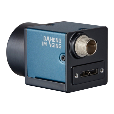
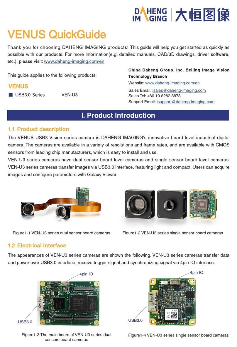
Daheng Imaging VENUS USB3 Series User manual

VENUS USB3 Vision Cameras
User Manual
Version: V1.0.0
Date: 2020-09-14
China Daheng Group, Inc. Beijing Image Vision Technology Branch

All rights reserved. No parts of this manual may be used or reproduced, in any forms or by any means,
without prior written permission of China Daheng Group, Inc. Beijing Image Vision Technology Branch.
The right is also reserved to modify or change any parts of this manual in the future without prior notification.
All other trademarks are the properties of their respective owners.
© 2020 China Daheng Group, Inc. Beijing Image Vision Technology Branch
Web:
http://www.daheng-imaging.com/en
Sales Email:
isales@daheng-imaging.com
Sales Tel:
+86 10 8282 8878
Support Email:
isupport@daheng-imaging.com

Preface
We really appreciate your choosing of DAHENG IMAGING products.
The VENUS USB3.0 series camera is DAHENG IMAGING's latest board level industrial digital camera
with large and high-quality sensor, featuring high resolution, high definition and extremely low noise. The
camera is equipped with standard USB3.0 interface, is easy to install and use.
The VENUS family cameras are especially suitable for machine vision applications such as industrial
inspection, medical, scientific research, education, security and so on.
This manual describes in detail on how to install and use the VENUS USB3 Vision digital cameras.

© China Daheng Group, Inc. Beijing Image Vision Technology Branch I
Contents
1. Introduction......................................................................................................................1
1.1. Series Introduction .................................................................................................. 1
1.2. Naming Rules.......................................................................................................... 1
1.3. Standards................................................................................................................ 1
1.4. Document, CAD/Technical Drawing and Software Downloads................................ 2
2. Precautions ......................................................................................................................3
2.1. Guideline for Avoiding EMI and ESD....................................................................... 3
2.2. Environmental Requirements .................................................................................. 3
2.3. Camera Mechanical Installation Precautions........................................................... 3
3. Installation Guideline ......................................................................................................4
3.1. Host Preparation ..................................................................................................... 4
3.1.1. Software Package ...............................................................................................................4
3.1.2. User Software Interface.......................................................................................................4
3.2. Camera Power ........................................................................................................ 5
3.3. Camera Driver Installation ....................................................................................... 6
3.3.1. System Requirements .........................................................................................................6
3.3.2. Driver Installation.................................................................................................................6
3.4. Open Device and Start Acquisition .......................................................................... 6
4. General Specification......................................................................................................7
4.1. Explanation of Important Parameters ...................................................................... 7
4.1.1. About Spectral Response.................................................................................................... 7
4.2. VEN-161-61U3M-(M01/M05/M06)........................................................................... 7
4.2.1. Parameter ............................................................................................................................7
4.2.2. Spectral Response ..............................................................................................................9
5. Dimensions ....................................................................................................................10
5.1. Camera Dimensions.............................................................................................. 10
5.2. Optical Interface .....................................................................................................11
6. Filters and Lenses .........................................................................................................13
6.1. Filters .................................................................................................................... 13
6.2. Lens Selection Reference ..................................................................................... 14
7. Electrical Interface.........................................................................................................16
7.1. LED Light............................................................................................................... 16
7.2. USB Port ............................................................................................................... 16
7.3. I/O Port.................................................................................................................. 16
7.3.1. VEN-U3 Series ..................................................................................................................16

© China Daheng Group, Inc. Beijing Image Vision Technology Branch II
7.3.1.1. Line0 (Opto-isolated Input) Circuit..............................................................................17
7.3.1.2. Line2 (Bidirectional) Circuit......................................................................................... 19
7.3.1.2.1. Line2 is Configured as Input ................................................................................19
7.3.1.2.2. Line2 is Configured as Output ............................................................................. 21
8. Features..........................................................................................................................24
8.1. I/O Control ............................................................................................................. 24
8.1.1. VEN-U3 Series ..................................................................................................................24
8.1.1.1. Input Mode Operation .................................................................................................24
8.1.1.2. Output Mode Operation ..............................................................................................25
8.1.1.3. Read the LineStatus ...................................................................................................27
8.2. Image Acquisition Control...................................................................................... 27
8.2.1. Acquisition Start and Stop .................................................................................................27
8.2.1.1. Acquisition Start ..........................................................................................................27
8.2.1.2. Acquisition Stop .......................................................................................................... 28
8.2.2. Acquisition Mode ...............................................................................................................29
8.2.3. Switching Trigger Mode.....................................................................................................30
8.2.4. Continuous Mode and Configuration.................................................................................31
8.2.5. Software Trigger Acquisition and Configuration ................................................................31
8.2.6. External Trigger Acquisition and Configuration .................................................................32
8.2.7. Set Exposure ..................................................................................................................... 33
8.2.7.1. Set Exposure Mode .................................................................................................... 33
8.2.7.2. Set Exposure Value ....................................................................................................34
8.2.8. Overlapping Exposure .......................................................................................................36
8.3. Basic Features ...................................................................................................... 37
8.3.1. Gain ................................................................................................................................... 37
8.3.2. Pixel Format.......................................................................................................................37
8.3.3. ROI..................................................................................................................................... 40
8.3.4. Auto Exposure/Auto Gain .................................................................................................. 41
8.3.5. Test Pattern........................................................................................................................43
8.3.6. User Set Control ................................................................................................................43
8.3.7. Device User ID ..................................................................................................................45
8.3.8. Reverse X and Reverse Y.................................................................................................46
8.3.9. User Data Area ..................................................................................................................48
8.4. Image Transmission .............................................................................................. 48
8.4.1. Calculate Frame Rate........................................................................................................ 48
8.4.2. USB Interface Bandwidth ..................................................................................................49
8.4.3. DeviceLinkThroughputLimit...............................................................................................49
8.4.4. Camera Acquisition Time...................................................................................................50
9. Software Tool .................................................................................................................51
9.1. LUT Create Tool .................................................................................................... 51
9.1.1. GUI..................................................................................................................................... 51
9.1.2. User Guide.........................................................................................................................52
© China Daheng Group, Inc. Beijing Image Vision Technology Branch III
9.1.2.1. User Case ...................................................................................................................52
9.1.2.2. GroupBox....................................................................................................................52
9.1.2.3. Auto Create Lut...........................................................................................................56
9.1.2.4. Save Lut......................................................................................................................57
9.1.3. Precautions........................................................................................................................57
9.1.3.1. Read From Device......................................................................................................57
9.1.3.2. Write To Device...........................................................................................................58
9.1.3.3. Directory Structure......................................................................................................58
9.2. Frame Rate Calculation Tool ................................................................................. 58
10. FAQ ...............................................................................................................................60
11. Revision History ..........................................................................................................62
12. Contact Us....................................................................................................................63
12.1. Contact Sales ...................................................................................................... 63
12.2. Contact Support .................................................................................................. 64

1.Introduction
© China Daheng Group, Inc. Beijing Image Vision Technology Branch 1
1. Introduction
1.1. Series Introduction
The VENUS USB3 Vision series camera is DAHENG IMAGING's innovative board level industrial digital
camera, featuring outstanding performance, powerful features, outstanding price/performance ratio. The
VEN-U3 series cameras are available in a variety of resolutions and frame rates, and are available with
CMOS sensors from leading chip manufacturers, which is easy to install and use.
The VEN-U3 series digital camera transmits image data through the USB3.0 data interface. Thanks to the
locking screw connectors, the VENUS series cameras can secure the reliability of cameras deployed in
harsh industrial environments. Featuring high reliability and high price/performance ratio, the VENUS
series cameras are especially suitable for machine vision applications such as industrial inspection,
medical, scientific research, education, security and so on.
1.2. Naming Rules
Details of the VENUS USB3 Vision series camera is given in the general specifications below. Each
camera model name is determined by its sensor's maximum resolution, maximum frame rate at maximum
resolution, the color/monochrome type of the sensor, etc.
Figure 1-1 Naming rules
1.3. Standards
The camera follows the USB3 Vision1.0 standard, and its development interface GalaxySDK is
implemented based on the GEN<i>CAM standard.

1.Introduction
© China Daheng Group, Inc. Beijing Image Vision Technology Branch 2
1.4. Document, CAD/Technical Drawing and Software Downloads
Product related document, CAD/Technical drawing and software can be downloaded from the Downloads
of DAHENG IMAGING website. The relevant contents are as follows:
Document
VENUS USB3 Vision Cameras User Manual
CAD/Technical Drawing
DAHENG IMAGING VEN-U3 CAD/Technical Drawing
Software
Galaxy Windows SDK—USB3.0, GigE, MERCURY USB2.0 Cameras
Galaxy Linux SDK—USB3.0, GigE, MERCURY USB2.0 Cameras
Galaxy Android SDK—USB3.0 Cameras

2.Precautions
© China Daheng Group, Inc. Beijing Image Vision Technology Branch 3
2. Precautions
2.1. Guideline for Avoiding EMI and ESD
You should consider the EMI (Electro Magnetic Interference) and ESD (Electro-Static discharge) problem
in the process of using the camera, to guarantee the camera to work in a relatively good electromagnetic
environment. The main measures are as follows:
1) USB cables certificated by USB IF with lock screw are recommended.
2) Using shielded cable can avoid electro-magnetic interface. Shielding layer of the cable should conduct
to ground nearby and not until stretched too long. When many devices need conduct to ground, using
single point grounding to avoid earth loop.
3) Keep your cameras away from equipment with high voltage, or high current (such as motor, inverter,
relay, etc.). If necessary, use additional shielding.
4) ESD (electro-static discharge) may damage cameras permanently, so use suitable clothing (cotton)
and shoes, and touch the metal to discharge the electro-static before operating cameras.
2.2. Environmental Requirements
1) Housing temperature during operation: 0°C ~ 45°C, humidity during operation: 10% ~ 80%.
Storage temperature: -20°C ~ 70°C.
2) To avoid collecting dust in the optical filter, always keep the plastic cap on cameras when no lens is
mounted.
3) PC requirement: Intel Core 2 Duo, 2.4GHz or above, and 2GB memory or above.
4) USB3.0 host controller requirement: Intel controller integrated in mainboard is recommend. Select
Renesas controller if external frame grabber is needed.
5) The cable must have a locking screw at the end of the device.
6) Make sure that cameras are transported in the original factory packages.
2.3. Camera Mechanical Installation Precautions
Camera installation requirements:
1) The M3 screw and the camera should have a screw length between 2.5 and 2.7mm, and the M2 screw
and the camera should have a screw length between 3 and 3.3mm
2) The M3 screw assembly torque ≤ 1N.M, and the M2 screw assembly torque ≤ 0.5N.M. If the screw
assembly torque is too large, it may cause the camera thread stripping.

3.Installation Guideline
© China Daheng Group, Inc. Beijing Image Vision Technology Branch 4
3. Installation Guideline
3.1. Host Preparation
3.1.1. Software Package
The software package of DAHENG IMAGING's MERCURY2 series is used to control the MERCURY2 and
VENUS series camera to provide stable, real-time image transmission, and provides multiple samples and
easy-to-integrate SDKs for various programming tools. The package is composed of the following modules:
1) Driver Package (Driver): This package provides the VENUS series camera driver program, such as:
the USB3.0 cameras' driver program.
2) Interface Library (API): This package provides the camera control interface library and the image
processing interface library, supports the user for secondary development.
3) Demonstration Program (GalaxyView.exe): This demonstration program is used to display the camera
control, image acquisition and image processing functions, the user can control the camera directly
by the demonstration program, and the user can develop their own control program based on the
camera interface library.
4) Sample: These samples demonstrate cameras' functions, the user can easily use these samples to
control cameras, or refer to the samples to develop their own control programs.
5) Programmer's Manual: This manual is the users programming guide that instructs the users how to
configure the programming environment and how to control cameras and acquire images through the
camera interface library.
You can download the latest software package from the website: www.daheng-
imaging.com/en/Downloads.
3.1.2. User Software Interface
After installing the MERCURY2 series camera software package, the user can use the demonstration
program and the samples to control the camera, also the user can control the camera by the program
which is written by the user themselves. The software package provides three kinds of program interface,
the user can select the suitable one for use according to their own requirements:
1) API Interface
In order to simplify the users' programming complexity, the package provides the general C programming
interface GxIAPI.dll and image processing algorithm interface DxImageProc.dll for the user to control the
camera, and provides the samples and software development manual which are based on these interfaces.
The API interface supports C/C++/C#/Python, etc.
2) GenTL Interface
This interface is developed according to the standard of general transport layer in GEN<i>CAM standard,
DAHENG IMAGING follows the GEN<i>CAM standard and provides the GenTL interface for the user, the
user can use the GenTL interface directly to develop their own control program.

3.Installation Guideline
© China Daheng Group, Inc. Beijing Image Vision Technology Branch 5
In addition, users can use some third-party software that supports GEN<i>CAM standard to control the
camera, such as HALCON.
3) USB3 Vision interface
The VENUS series USB3.0 camera is compatible with the USB3 Vision protocol, which allows the user to
control the camera directly through the USB3 Vision protocol. In addition, the user can use some third-
party software that supports the USB3 Vision protocol to control the camera, such as HALCON.
⚫Note
GEN<i>CAM standard: GEN<i>CAM is administered by the European Machine Vision Association (EMVA).
GenICam provides a generic programming interface for all kinds of cameras and devices. It provides a
standard application programming interface (API), no matter what interface technology is being used. It
mainly includes the following modules:
➢GenAPI: an XML description file format defining how to capture the features of a device and how to
access and control these features in a standard way
➢GenTL: a generic Transport Layer Interface, between software drivers and libraries, that transports
the image data from the camera to the application running on a PC
➢SFNC: common naming convention for camera features, which promotes interoperability between
products from different manufacturers
Figure 3-1 GEN<i>CAM standard schematic diagram
3.2. Camera Power
VEN-U3 series camera is powered by the USB 3.0 interface.

3.Installation Guideline
© China Daheng Group, Inc. Beijing Image Vision Technology Branch 6
3.3. Camera Driver Installation
3.3.1. System Requirements
GalaxySDK is suitable for all cameras in the VENUS series. The GalaxySDK contains various operating
systems such as Windows, Android and Linux. The requirements for the operating system and version of
the installation package are as follows:
Operating Systems
Applicable Version
Windows
➢Windows XP (32bit, 64bit)
➢Windows 7 (32bit, 64bit)
➢Windows 8 (32bit, 64bit)
➢Windows 8.1 (32bit, 64bit)
➢Windows 10 (32bit, 64bit)
Linux
➢Ubuntu 12.04 or above, kernel version 3.5.0.23 or above
Android
➢Android6 or above
3.3.2. Driver Installation
The steps to install the Galaxy SDK under Windows are as follows:
1) Download the corresponding version of the installation package from www.daheng-
imaging.com/en/Downloads.
2) Run the installer.
3) Follow the instructions of the installation wizard to complete the installation process. During the
installation process, you can choose the camera interface you need (USB2.0, USB3 Vision, GigE
Vision, etc.).
During the installation process, especially when installing the *.sys file, you must always pay attention to
whether the anti-virus software intercepts the driver. If intercepted, it may cause the driver installation to
fail.
3.4. Open Device and Start Acquisition
After powering the device, connecting the device to the USB3.0 interface of the host. Double-click the
GalaxyView software to acquire image. The steps are as follows:
1) Click the icon on the toolbar in the GalaxyView to refresh device list.
2) After the device is enumerated, double-click the device enumerated in the device list.
3) Click the icon on the toolbar to perform the Start Acquisition operation on the current device.

4.General Specification
© China Daheng Group, Inc. Beijing Image Vision Technology Branch 7
4. General Specification
4.1. Explanation of Important Parameters
4.1.1. About Spectral Response
QE: Quantum efficiency, which is the ratio of the average number of photoelectrons produced per unit time
to the number of incident photons at a given wavelength.
Sensitivity: The change of the sensor output signal relative to the incident light energy. The commonly
used sensitivity units are V/((W/m2)·s), V/lux·s, e-/((W/m2)·s) or DN/ ((W/m2)·s).
The spectral response graphs given by different manufacturers are different. Some graphs' ordinate is
relative sensitivity response, and abscissa is wavelength. Some graphs' ordinate is QE, and abscissa is
wavelength.
4.2. VEN-161-61U3M-(M01/M05/M06)
4.2.1. Parameter
Specifications
VEN-161-61U3M-M06
VEN-161-61U3M-M01
VEN-161-61U3M-M05
Resolution
1440 × 1080
Sensor Type
Sony IMX296 global shutter CMOS
Optical Size
1/2.9 inch
Pixel Size
3.45μm × 3.45μm
Frame Rate
61.2fps@1440 × 1080
ADC Bit Depth
10bit
Pixel Bit Depth
8bit, 10bit
Shutter Time
20μs~1s
Gain
0dB~24dB
Pixel Data
Formats
Mono8/Mono10
Signal Noise
Ratio
40.6dB
Synchronization
External trigger, software trigger

4.General Specification
© China Daheng Group, Inc. Beijing Image Vision Technology Branch 8
I/O
1 input with opto-isolated, 1 programmable GPIO
Operating Temp.
0°C~45°C
Storage Temp.
-20°C~70°C
Operating
Humidity
10%~80%
Power
Consumption
< 2.7W@5V
Lens Mount
-
CS
S
Dimensions
32.5mm×32.5
mm×8.1mm (PCB
thickness is 1.6mm)
35mm×35mm×15.8mm
(without CS-mount lens
adapter or connectors)
35mm×35 mm×15.1mm
(without S-mount lens
adapter or connectors)
Weight
7g
31g
32g
Software
Windows XP/Win7/Win8/Win10 32bit, 64bit OS
Data Interface
USB3.0
Programmable
Control
Image size, gain, exposure time, trigger polarity, flash polarity
Conformity
CE, RoHS, FCC, USB3 Vision, GenICam
Table 4-1 VEN-161-61U3M-(M01/M05/M06) camera specifications

4.General Specification
© China Daheng Group, Inc. Beijing Image Vision Technology Branch 9
4.2.2. Spectral Response
Figure 4-1 VEN-161-61U3M-(M01/M05/M06) sensor spectral response

5.Dimensions
© China Daheng Group, Inc. Beijing Image Vision Technology Branch 10
5. Dimensions
5.1. Camera Dimensions
Figure 5-1 VEN-U3-M01 mechanical dimensions
Figure 5-2 VEN-U3-M06 mechanical dimensions

5.Dimensions
© China Daheng Group, Inc. Beijing Image Vision Technology Branch 11
Figure 5-3 VEN-U3-M05 mechanical dimensions
5.2. Optical Interface
VEN-U3 cameras are equipped with CS-mount and S-mount lens adapters. The back-flange distance of
CS-mount is 12.526 mm (in the air), and the maximum lens allowed thread length should be less than
6.3mm, as shown in Figure 5-4. The back-flange distance of S-mount is 13.18 mm (in the air), and the
maximum screw-in depth of the S-mount lens should be less than 11.6mm, as shown in Figure 5-5.
The CS-mount color models are equipped with an IR filter and the cut-off frequency is 700nm. The mono
models are equipped with a transparent glass. Remove IR-filter or transparent glass will defocus the image
plane.
Contact our technical support when the glass needed to be removed.

5.Dimensions
© China Daheng Group, Inc. Beijing Image Vision Technology Branch 12
Figure 5-4 CS-mount optical interface of VENUS
Figure 5-5 S-mount optical interface of VENUS

6.Filters and Lenses
© China Daheng Group, Inc. Beijing Image Vision Technology Branch 13
6. Filters and Lenses
6.1. Filters
The VENUS color models of CS-mount are equipped with IR filters. The monochrome models are equipped
with transparent glasses.
Contact our technical support when the glass needed to be removed.
Figure 6-1 Infrared cut-off filter transmittance curve for VENUS series color camera
Figure 6-2 Transparent glass reflectance curve for VENUS series mono camera

6.Filters and Lenses
© China Daheng Group, Inc. Beijing Image Vision Technology Branch 14
6.2. Lens Selection Reference
DAHENG IMAGING is a professional supplier for images and machine vision devices in China. In addition
to industrial cameras, it also provides high-resolution, high-optical machine vision lenses for a wide range
of industrial cameras on the market.
In order to meet the requirements of machine vision for high resolution and low distortion, DAHENG
IMAGING released two series of lenses, including industrial lenses of 2 megapixels and 5 megapixels,
with small size, light weight, high resolution and low distortion rate, etc.
When choosing a lens, there are several factors to consider:
1) Mount
⚫The lens and camera connection methods, commonly used mounts include C, CS, S, and so on
⚫The VENUS series USB3.0 digital camera is equipped with standard CS-mount and S-mount. When
selecting a lens, select the lens of the same mount as the camera. The CS-mount can use the C-
mount lens by matching the CS-mount to C-mount adapter ring.
2) Optical size
⚫The maximum sensor size that the lens image can cover. There are mainly 1/2", 2/3", 1/1.2", 1 ", and
so on
⚫When selecting a lens, make sure that the optical size of the lens is not smaller than the sensor size
of the digital camera
3) Resolution
⚫The resolution represents the ability of the lens to record the details of the object, usually in units of
line pairs that can be resolved per millimeter: line pair/mm (lp/mm). The higher the resolution of the
lens, the sharper the image
⚫When selecting a lens, make sure that the accuracy required by the system is less than the resolution
of the lens
4) Working distance
⚫The distance from the first working surface of the lens to the object being measured
⚫When selecting a lens, make sure that the working distance is larger than the lens parameter
"minimum object distance"
5) Focal length
⚫The focal length is the distance from the center point of the lens to the clear image formed on the focal
plane. The smaller the focal length, the larger the field of view of the digital camera
⚫For focal length calculation, we need to confirm three parameters: the field of view, the sensor size of
the digital camera and the working distance. The focal length (f) of the expected lens can be calculated
by the following formula
Other manuals for VENUS USB3 Series
2
This manual suits for next models
4
Table of contents
Other Daheng Imaging Digital Camera manuals

Daheng Imaging
Daheng Imaging MARS GigE User manual

Daheng Imaging
Daheng Imaging MERCURY2 USB3 User manual

Daheng Imaging
Daheng Imaging VENUS USB3 Series User manual

Daheng Imaging
Daheng Imaging MER-030-120UC-L User manual

Daheng Imaging
Daheng Imaging MERCURY2 GigE Series User manual

Daheng Imaging
Daheng Imaging MARS USB3 User manual

Daheng Imaging
Daheng Imaging VEN-134-90U3M-D User manual

Daheng Imaging
Daheng Imaging VENUS USB3 Series User manual

Daheng Imaging
Daheng Imaging MERCURY2 GigE Series User manual