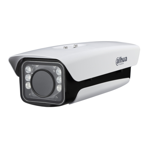
Dahua Technology DHI-ITC952-RF2D User manual

Dahua HD Intelligent Traffic Camera
User's Manual
V1.0.1
ZHEJIANG DAHUA VISION TECHNOLOGY CO., LTD.

Regulatory Information II
Regulatory Information
FCC Information
Changes or modifications not expressly approved by the party responsible for compliance
could void the user's authority to operate the equipment.
FCC conditions:
This device complies with Part 15 of the FCC Rules. Operation is subject to the following two
conditions:
This device may not cause harmful interference, and
This device must accept any interference received, including interference that may cause
undesired operation.
FCC compliance:
This equipment has been tested and found to comply with the limits for a digital device,
pursuant to Part 15 of the FCC Rules. This equipment generates, uses and radiates radio
frequency energy and, if not installed and used in accordance with the guide, may cause
harmful interference to radio communication.
For ClassA device, these limits are designed to provide reasonable protection against
harmful interference in a commercial environment. Operation of this equipment in a
residential area is likely to cause harmful interference, in which case the user will be
required to correct the interference at his or her own expense.
For Class B device, these limits are designed to provide reasonable protection against
harmful interference in a residential installation. However, there is no guarantee that
interference will not occur in a particular installation. If this equipment does cause harmful
interference to radio or television reception, which can be determined by turning the
equipment off and on, the user is encouraged to try to correct the interference by one or
more of the following measures:
Reorient or relocate the receiving antenna.
Increase the separation between the equipment and receiver.
Connect the equipment into an outlet on a circuit different from that to which the
receiver is connected.
Consult the dealer or an experienced radio/TV technician for help.

Foreword III
Foreword
General
This User's Manual (hereinafter referred to as "the Manual") introduces the functions and
features, structure, installation, system networking, network access, quick configuration method,
and FAQ of intelligent traffic HD camera (hereinafter referred to as "the Camera").
Models
Model
Pixel
DHI-ITC952-RF2D
9 MP
DHI-ITC952-RF2D-IR
DHI-ITC352-RF2D
3 MP
DHI-ITC352-RF2D-IR
Safety Instructions
The following categorized signal words with defined meaning might appear in the Manual.
Signal Words
Meaning
Indicates a high potential hazard which, if not avoided, will result in
death or serious injury.
Indicates a medium or low potential hazard which, if not avoided,
could result in slight or moderate injury.
CAUTION
Indicates a potential risk which, if not avoided, may result in
property damage, data loss, lower performance, or unpredictable
result.
ELECTRICITY
Indicates dangerous high voltage.
Take care to avoid coming into contact with electricity.
LASER BEAM
Indicates a laser radiation hazard.
Take care to avoid exposure to a laser beam.
ESD
Electrostatic sensitive devices.
Indicates a device that is sensitive to electrostatic discharge.

Foreword IV
Signal Words
Meaning
TIPS
Provides methods to help you solve a problem or save you time.
NOTE
Provides additional information as the emphasis and supplement to
the text.
Revision History
No.
Version
Revision Content
Release Time
1
V1.0.1
Update
April 2019
2
V1.0.0
First release
January 2019

Important Safeguards and Warnings V
Important Safeguards and Warnings
Operation Requirement
Do not place or install the Camera in a place exposed to sunlight or near the heat source.
Keep the Camera away from dampness, dust or soot.
Keep the Camera installed horizontally on the stable place to prevent it from falling.
Do not drop or splash liquid onto the Camera, and make sure there is no object filled with
liquid on the Camera to prevent liquid from flowing into the Camera.
Install the Camera in a well-ventilated place, and do not block the ventilation of the
Camera.
Operate the Camera within the rated range of power input and output.
Do not dissemble the Camera.
Transport, use and store the Camera under the allowed humidity and temperature
conditions.
Electrical Safety
Improper battery use might result in fire, explosion, or inflammation.
When replacing battery, make sure the same model is used.
Use the recommended power cables in the region and conform to the rated power
specification.
Use the power adapter provided with the Camera; otherwise, it might result in people injury
and device damage.
The power source shall conform to the requirement of the Safety Extra Low Voltage (SELV)
standard, and supply power with rated voltage which conforms to Limited power Source
requirement according to IEC60950-1. Please note that the power supply requirement is
subject to the device label.
Connect the device (I-type structure) to the power socket with protective earthing.
The appliance coupler is a disconnection device. When using the coupler, keep the angle
for easy operation.
Maintenance Requirement
Do not try to disassemble the Camera yourself.
Do not touch charge-coupled device (CCD) or complementary metal oxide semiconductor
(CMOS) directly. Use a blower to remove dust or dirt from the sensor surface.
Use a soft, dry and clean cloth soaked with a small amount of neutral detergent to clean
the Camera.

Table of Contents VI
Table of Contents
Regulatory Information............................................................................................................................ II
Foreword.................................................................................................................................................. III
Important Safeguards and Warnings.....................................................................................................V
1 Overview................................................................................................................................................. 1
Introduction ................................................................................................................................... 11.1 Functions....................................................................................................................................... 11.2
2 Structure................................................................................................................................................. 4
Rear Panel.................................................................................................................................... 42.1 Side Panel..................................................................................................................................... 62.2 Front Panel.................................................................................................................................... 62.3
3 Installation.............................................................................................................................................. 7
Motorized Varifocal Lens............................................................................................................... 73.1 3.1.1 Installing the Lens............................................................................................................... 7
3.1.2 Removing the Lens............................................................................................................. 8
TF Card......................................................................................................................................... 83.2 3.2.1 Installing TF Card ............................................................................................................... 8
3.2.2 Removing TF Card ............................................................................................................. 9
I/O Interface .................................................................................................................................. 93.3 3.3.1 Installing the Cable........................................................................................................... 10
3.3.2 Removing the Cable......................................................................................................... 10
Corrugated Pipe.......................................................................................................................... 103.4
4 System Network .................................................................................................................................. 11
5 ConfigTool............................................................................................................................................ 12
Modifying IP Address .................................................................................................................. 125.1 Upgrading the Camera................................................................................................................ 135.2 Logging in Web........................................................................................................................... 145.3 Setting Search............................................................................................................................. 155.4
6 Web Configuration .............................................................................................................................. 16
Web Introduction......................................................................................................................... 166.1 6.1.1 First-time Login................................................................................................................. 16
6.1.2 Login................................................................................................................................. 19
6.1.3 Functions .......................................................................................................................... 20
Guide........................................................................................................................................... 206.2 6.2.1 Work Mode........................................................................................................................ 20
6.2.2 PTZ................................................................................................................................... 23
6.2.3 Plate-pixel Check.............................................................................................................. 25
6.2.4 Trigger Mode..................................................................................................................... 28
6.2.5 Lamp Config ..................................................................................................................... 33
6.2.6 Lane Property................................................................................................................... 33
6.2.7 Complete........................................................................................................................... 34
Live.............................................................................................................................................. 356.3
Table of Contents VII
Query........................................................................................................................................... 366.4 6.4.1 Picture Query.................................................................................................................... 37
6.4.2 Flow Query........................................................................................................................ 39
6.4.3 Record Query ................................................................................................................... 40
Setting......................................................................................................................................... 416.5 6.5.1 ITC (Intelligent Traffic Camera) ........................................................................................ 41
6.5.2 Camera............................................................................................................................. 71
6.5.3 Network............................................................................................................................. 79
6.5.4 Remote Device................................................................................................................. 81
6.5.5 Event.................................................................................................................................82
6.5.6 Storage ............................................................................................................................. 86
6.5.7 System.............................................................................................................................. 89
6.5.8 Information...................................................................................................................... 108
Alarm..........................................................................................................................................1116.6 Logout ........................................................................................................................................1126.7 FAQ.................................................................................................................................... 113Appendix 1 Cybercurity Recommendations ..................................................................................... 114Appendix 2

Overview 1
1 Overview
Introduction1.1
The Camera uses embedded operating system and advanced video technology of H.264
encoding (some models support H.265 encoding) to realize flexible capture.
It can record videos of different surveillance scenes, and transmit video data to controller,
central server or storage device through network.
The Camera is extensively applied to traffic surveillance system of highways and city roads. It
can effectively monitor violations such as speeding, wrong-way driving, unfastened safety belt,
running a red light, etc. It provides effective ways for modern traffic management.
Functions1.2
This section introduces some of the functions for your reference. The functions may vary
according to the model, and the actual functions of the model shall prevail.
Picture Composition
Composites several pictures of violations into one picture, and the composition way is flexible.
Picture Cutout
With sufficient light supplement of flashing light, when capturing one vehicle, the Camera can
also cut out the plate number part of the snapshot. Camera inANPR mode can even cut out the
face picture of people in the front.
Intelligent Recognition
Recognizing license plate, logo, series, color, model, sun visor, safe belt, face of driver, etc.
Detecting violations such as speeding, unfasten safety belt, etc.
User Management
Configuring multiple user groups and users, and each user groups and user can be
configured with different authorities.
Querying information of online users.
Log Management
Storing up to 1,792 log records.

Overview 2
User permission control.
Storage
Stores the record data on central server according to the storage policy configured by user.
After recording according to user needs and by web recording mode, video files are stored
on the client computer.
TF card local storage, hot swapping, and ANR (automatic network replenishment). When
storage space is insufficient, it automatically overlays the stored files.
Alarm
Sending alarm of camera abnormity (such as storage damage) through network.
Connecting to external alarm devices through alarm inputs, and real-time response to
external alarm inputs within 200ms.
Processing alarm information and sending voice prompt according to predefined alarm
settings by user.
Network Surveillance
Through network, single-channel record data compressed by the Camera is transmitted to
the network terminal for decompression and reconstruction. 400ms delay at most if
bandwidth allows.
Max supports 10 connections.
Adopts the followingA/V transmission protocol: HTTP, TCP, UDP, MULTICAST, RTP/RTCP,
etc.
Supports web access, widely used in WAN.
Traffic Flow Statistics
Traffic flow statistics of lane is realized through connection to traffic signal controller or camera.
Uploading statistics data to corresponding platform server.
Snapshot
Snapshot and coding of images.
Supports watermark encryption to prevent tampering.
You can configure the speed limit and interval of snapshot.
The captured picture displays the time, place, speed, speed limit, and lane of vehicle, as
well as picture number, violation type, etc.
Snapshot of traffic violations.
Record Linkage
Recording the violations of vehicles, and linking snapshots to the record.
OSD Settings

Overview 3
You can configure the OSD information and location of video channel, picture, and composite
picture.
Network Management
Configuration and permission management through Ethernet.
Managing the Camera by web.
Peripheral Device Control
Peripheral device management. The control protocol and interface of such device can be
configured freely.
Supports connection to peripheral devices such as flashlight, strobe light, vehicle detector,
signal detector, radar, etc.
Power Supply
AC synchronization. 12V DC power supply.
White Balance
Automatic white balance: Accurately reflecting the color balance when the illumination
source changes.
Partial white balance: Adjusting the color balance according to the surrounding
environment.
Automatic Exposure
Automatically determines the correct exposure for captured pictures, and the shutter speed
based on the factory settings of aperture and shutter speed.
Automatic Gain
Automatically increases the sensitivity of camera when the illumination is weak, and enhances
image signal output for clear, bright images.
Auxiliary Functions
Watermark encryption of video image coding to prevent tampering.
Real-time display of system resource information and running status. Supports log
function.
Signal control and output of strobe light, flashing light, and continuous light.
GPS positioning.

Structure 4
2 Structure
Rear Panel2.1
Rear panelFigure 2-1
Table 2-1 Rear panel interfaces
Interface
Function
DC 12 IN
Power input
interface
12V DC input.
SI+, SI-
Synchronous
input interface of
external
frequency source
The camera synchronizes with external signal source
(automatically works after selecting external
synchronous. Voltage range: 12 Vp-p–36 Vp-p, or AC
12V–AC 24V).
RESET
Reset button
Restore to factory default settings. When system runs
normally (the power indicator light is blue), press and
hold the RESET button for at least 5 seconds, and the
system restores to factory default settings.
STATUS
Indicator light
Displays the activity status of the camera. The status of
indicator light is as follows:
The blue light keeps on when the system runs
normally.
The red light flashes when the system is updating.
The red light keeps on in safety mode.
DC 12 OUT
Power output
interface
12V DC output.
GPS
Used for connecting GPS antenna.

Structure 5
Interface
Function
V-OUT
Video output
CVBS
CVBS (1.0Vp-p, 75Ω).
F1+, F1-, F2+,
F2-, F3+, F3-,
F4+, F4-, F5+,
F5-, F6+, F6-,
F7+, F7-
7-channel ports
Connect flashing light and strobe.
The configuration must be consistent with the light
actually connected, otherwise it is prone to burn out the
light.
A1
RS-485 ports
RS485-A1 port, connecting to signal detector, vehicle
detector, radar, etc.
B1
TRS485-B1 port, connecting to signal detector, vehicle
detector, radar, etc.
A2
RS485-A2 port, connecting to motorized varifocal lens.
B2
RS485-B2 port, connecting to motorized varifocal lens.
G
GND
Ground terminal.
IN1, IN2, IN3,
IN4
Input port
4 snapshot ports or 4 alarm input ports.
AO1, AO2
2-channel alarm
output
Can be configured respectively as alarm output port
and wiper output port.
R1 T1 G
R2 T2 G
R3 T3 G
3-channel radar
port
Simultaneous connection of 3 radars.
R
RS-232 ports
RS232_RX, RS232 port receiving terminal.
T
RS232_TX, RS232 port transmitting terminal.
2 network ports
Connect standard Ethernet cable.
USB-1/USB-2
2 USB ports
Used for accessing 3G, 4G, and Wi-Fi.
GND
Ground this port to improve reliability of the Camera,
otherwise the Camera might be exposed to lightning
strikes.
AUDIO
IN/OUT
Audio
input/output
Audio input/output interface.
TF card port
Connect TF card. Instructions for using TF card:
Before inserting the TF card into the slot, make
sure write protection is disabled in the card.
When removing the TF card, make sure the card is
not in read/write status; otherwise, it might cause
data loss and TF card damage.
When hot swapping the TF card, stop recording
first.
SIM card slot
Preserved interface.
Antenna slot
4G antenna.

Structure 6
Side Panel2.2
Side panel dimensions (mm)Figure 2-2
Front Panel2.3
Front panel dimensions (mm)Figure 2-3

Installation 7
3 Installation
To ensure proper grounding of the Camera and improve device reliability, connect the Camera
interface to the ground.
GNDFigure 3-1
Motorized Varifocal Lens3.1
This section takes some models as the example, and the actual model shall prevail.
3.1.1 Installing the Lens
Remove the protective covers of sensor and lens. Insert the spacer in between the lensStep 1 and the camera.
Align the lens to the lens mount position on the camera, and turn the lens clockwiseStep 2 until it is securely mounted. See Figure 3-2.

Installation 8
Installing the lensFigure 3-2
Insert the cable plug of lens into the auto iris lens connector on the side panel ofStep 3 camera.
Correct the focus to make the images clear.Step 4
3.1.2 Removing the Lens
Removing the lensFigure 3-3
Unplug the cable from the lens mount.Step 1 Turn the lens to counter-clockwise until the lens is removed. See Figure 3-3.Step 2 Install the protective covers of sensor and lens to prevent them from being spotted.Step 3
TF Card3.2
This section takes some models as the example, and the actual model shall prevail.
3.2.1 Installing TF Card
Insert the TF card according to the direction shown by the arrow. See Figure 3-4.

Installation 10
3.3.1 Installing the Cable
Insert the screwdriver into the square slot corresponding to the connecting cable. PressStep 1 the screwdriver vertically to loosen and expose the metal sheet of the circular slot.
Insert the cable into the circular slot.Step 2 Remove the screwdriver, and the cable installation is finished.Step 3
3.3.2 Removing the Cable
Insert the screwdriver into the square slot corresponding to the connecting cable. PressStep 1 the screwdriver vertically to loosen and expose the metal sheet of the circular slot.
Pull the cable out of the circular slot.Step 2 Remove the screwdriver, and the cable is disassembled.Step 3
Corrugated Pipe3.4
The corrugated pipe helps protect the cable.
Pull the cable into the corrugated pipe, and then pass the cable through the hole at the bottom
of the device.After the cable is properly placed, insert the corrugated pipe into the hole until it is
securely clamped.

System Network 11
4 System Network
As the center of traffic surveillance system, the Camera can record videos of different
surveillance scenes, and transmit video data to controller, central server or back-end storage
device through network. See Figure 4-1. System networkFigure 4-1
Video detector
Radar
Flashing light
Strobe
Client
Storage device
Vehicle detector
…
…
HD intelligent
traffic camera
Central server

ConfigTool 12
5 ConfigTool
Get the quick configuration tool by downloading and registering ConfigTool. You can use
ConfigTool to search device IP, modify the IP, and upgrade the system.
This section takes ConfigTool 4.07.0 as the example. Different versions may have different
interfaces, and the actually downloaded ConfigTool shall prevail.
Open ConfigTool, and on the Devices found page, you can see the device information, such
as status, type, model, IP, MAC, and version. See Figure 5-1.
Main interfaceFigure 5-1
Modifying IP Address5.1
Open ConfigTool.Step 1
Click .Step 2
The Modify IP interface is displayed. See Figure 5-1.
Click the device that you want to modify the IP.Step 3
Modify one device: Click corresponding to the device.
Batch modify: Select the devices, and click Modify IP.
Configure mode, IP, subnet mask and gateway. See Figure 5-2.Step 4

ConfigTool 13
For batch modify, selecting Same IP means setting the selected devices as the same
IP. Batch modifyFigure 5-2
Click OK.Step 5
Upgrading the Camera5.2
Supports upgrading one device or batch upgrade.
Open ConfigTool.Step 1
Click , and the Upgrade interface is displayed. See Figure 5-3.Step 2
UpgradeFigure 5-3
Select the device you want to upgrade.Step 3
This manual suits for next models
3
Table of contents
Other Dahua Technology Digital Camera manuals

Dahua Technology
Dahua Technology D-ITC237-PW6M-IRLZF1050-B User manual

Dahua Technology
Dahua Technology DHI-ITC237-PW6M-LZF1050 User manual

Dahua Technology
Dahua Technology DH-IPC-HDEW8441R-Z User manual

Dahua Technology
Dahua Technology DHI-ITC237-PU1B-IR-PAX User manual

Dahua Technology
Dahua Technology DH-HAC-ME1500C User manual

Dahua Technology
Dahua Technology NKB1000 User manual

Dahua Technology
Dahua Technology COP Security ITC237-PU1A-IRHL User manual

Dahua Technology
Dahua Technology ITC1652 Instructions for use

Dahua Technology
Dahua Technology K Series User manual

Dahua Technology
Dahua Technology 22204UENI-W User manual