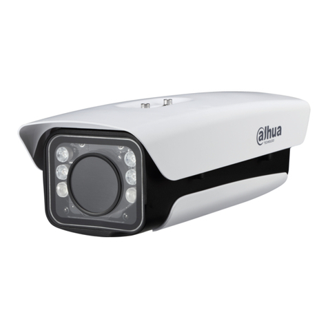
Dahua Technology ITC1652 Instructions for use

1
All-in-One Enforcement Camera ITC1652
Side Mounting Construction Guide

Construction Guide
I
Table of Contents
1 Main devices in the System........................................................................................................................... 1
Device List..................................................................................................................................................................................... 1
Device Introduction .................................................................................................................................................................. 1
1.2.1 All-in-One Enforcement Camera............................................................................................................................. 1
1.2.2 Edge Storage Device.................................................................................................................................................... 3
2 Installation Scheme....................................................................................................................................... 4
3 Installation Procedures ................................................................................................................................. 5
Installing the Bracket and the Camera............................................................................................................................... 5
Connecting the Cables............................................................................................................................................................. 6
3.2.1 Overall Wiring................................................................................................................................................................. 6
3.2.2 Connecting the Power Cord ..................................................................................................................................... 7
3.2.3 Connecting the Network Cable............................................................................................................................... 7
4 Commissioning.............................................................................................................................................. 8
Initializing the Camera ............................................................................................................................................................. 8
Adjusting the Scene.................................................................................................................................................................. 8
Adjusting the Focus ................................................................................................................................................................10
5 Configuration on the Webpage .................................................................................................................. 12
Synchronizing the Time.........................................................................................................................................................12
Configuring the Line...............................................................................................................................................................12
Configuring the Illuminator .................................................................................................................................................13
Checking the Snapshot..........................................................................................................................................................13
6 Edge Storage Device ITSE0804 ................................................................................................................... 15
Initializing the Device.............................................................................................................................................................15
Synchronizing the Time.........................................................................................................................................................16
Configuring the IP Address...................................................................................................................................................16
Adding Camera .........................................................................................................................................................................17
Configuring Recording and Capturing ............................................................................................................................17
Searching for Videos and Snapshots ................................................................................................................................18
Construction Guide
1
1Main Devices in the System
Device List
Name Model
Dahua 16MP All-in-
One Enforcement
Camera (with 16 mm–40 mm vari-focal
lens)
DHI-ITC1652-AU5F-LZF1640-C1
DHI-ITC1652-AU5F-IRL7ZF1640-C1
DHI-ITC1652-AU5F-IRL8ZF1640-C1
Side mounting brackets DHI-ITSZJ-3101-M
Pole mounting bracket DH-PFA150
Edge Storage Terminal DHI-ITSE1200-TA
Device Introduction
1.2.1 All-in-One Enforcement Camera
Table 1-1 Component description
No.
Description
1 16 mm–40 mm lens
2
Camera
3
Terminal blocks
4
Adapter

Construction Guide
2
Terminal blocks
Table 1-2 Interfaces of the terminal block
Pin No. Description
F1+ Flashing light 1 triggers output F1+
F1– Flashing light 1 triggers output F1-
F2+ Flashing light 2 triggers output F2+
F2– Flashing light 2 triggers output F2-
F3+ Flashing light 3 triggers output F3+
F3– Flashing light 3 triggers output F3-
F4+ Flashing light 4 triggers output F4+
F4– Flashing light 4 triggers output F4-
F7+ Strobe light synchronous output F7+
F7– Strobe light synchronous output F7–
A1 RS-485-A1
B1 RS-485-B1
L Live wire, 220 VAC
N Neutral wire, 220 VAC
PE Grounding wire, 220VAC

Construction Guide
3
1.2.2 Edge Storage Device
Device front
Device rear
Table 1-3 Key interfaces of the edge storage device
Name Description
POWER Power switch
DV 12V 12 VDC power interface
RESET Reset button. Press and hold the button for 10 s to restore the device to factory settings.
G1, G2 2 × Gigabit Ethernet ports on different network segments.
10/100M 12 × RJ45 Ethernet ports, at the same network segment with G2

Construction Guide
4
2Installation Scheme
Installation diagram
23 m
6 m
Triggering line
Side mount the camera on the pole mounting bracket, and attach the bracket to the pole at a
height of 6 meters.
The recommended horizontal distance is 23 meters, and 4 lanes are covered.
Use the included 16 mm–40 mm vari-focal lens.
Place the terminal, switch and other devices in the pole mounted or floor-standing cabinet.

Construction Guide
5
3Installation Procedures
Installing the Bracket and the Camera
Attach the connector of the side mounting bracket to the bottom of the camera enclosure.
Secure the base of the side mounting bracket to the pole mounting bracket.
Attach the side mounting bracket to the camera.

Construction Guide
6
Use hold loops to secure the pole mounting bracket to the pole.
Connecting the Cables
Overall Wiring

Construction Guide
7
3.3.1 Connecting the Power Cord
DANGER
Cut off the power supply before connecting the cables.
Power supply: 220 VAC.
Connect live wire to L port, neutral wire to N port and grounding wire to PE port.
Press and hold the button of the corresponding slot with a small slotted screwdriver.
Insert the cable into the slot.
Remove the slotted screwdriver, and the installation is complete.
3.3.2 Connecting the Network Cable
Connect the network cable of the camera to 1of the 8 Ethernet ports. We recommend you
connect the network cable in sequence.
Connect the terminal to the switch through the G2 port.

Construction Guide
8
4Commissioning
Initializing the Camera
Log in to the webpage of the camera (default IP address: 192.168. 1.108).
Follow the on-screen instructions to modify the password and IP address of the camera.
After the initialization is complete, go to the home page, and then download and install the
plug-in.
Adjusting the Scene
Such effect should be realized:
The horizontal position where the camera takes snapshots is at the lower 1/3 part of the screen,
and the vertical distance between the capturing position and the camera is 23 meters.
The monitored lanes should be completely covered and located in the center of the video image.

Construction Guide
9
The license plate is horizontal and level in the monitoring image.
On the Live page, click to adjust the lens.
Loose the screw on the bottom of the side mounting bracket with an Allen wrench to adjust
the position of the camera.
Adjust the zoom in and zoom out parameters to adjust the monitoring image.

Construction Guide
10
Adjusting the Focus
We recommend you perform focusing in daytime.
Place a traffic cone 23 meters away from the pole, and hang the license page on the cone.
Adjust the focus through Autofocus, and observe the definition of the image at the same time.
Use the zoom function to zoom in to the position where the license plate is placed. Reduce
the focus speed to 5 and 1, and adjust the + and – buttons to find out the position with the
best focusing effect as the image gets blurred and then clear.

Construction Guide
11
Make sure the edge and each character on the license plate is clear to human eyes in the
image, and defocus is not allowed.

Construction Guide
12
5Configuration on the Webpage
This section only introduces the configuration steps of ANPR function. For more functions, see the user’s
manual.
Synchronizing the Time
On the home page, select Setting > System > General > Date & Time.
Set the time zone to Beijing, click Sync PC or manually enter the time to synchronize the
system time, and then click Save.
Configuring the Line
On the home page, select Setting > Event > ANPR Snap > Illegal Capture.
Select lane 1, click Lane Line to draw lane lines in the monitoring image, and then click
Detection Line to draw detection line on the lane lines.
The detection line should be 23 m away from the camera.
Repeat the steps to draw lane lines and detection lines for lane 2 and lane 3.
Click Area Line in Vehicle Detection to draw the area lines on the lower part of the image.
After the configuration is complete, enable the events for the lanes, and then click Save.

Construction Guide
13
Configuring the Illuminator
On the home page, select Setting > Peripheral > External Light.
Set the parameters for the external light.
For example, if a strobe light is connected to F7+ and F7- ports, you need to select Strobe for
port 7. For the output mode, select Auto for the strobe light to turn on at night, and Strobe
On for the light to be solid on.
Checking the Snapshot
On the Live page, select Picture Preview to check the snapshot.

Construction Guide
14

Construction Guide
15
6Edge Storage Device ITSE0804
This section only introduces the configuration steps of snapshots capturing and video
storage. For more functions, see the user’s manual.
Initializing the Device
Log in to the webpage of the device (default IP address: 192.168. 0.108)
Follow the on-screen instructions to modify the password and IP address.
After the initialization is complete, go to the home page, and then download
and install the plug-in.

Construction Guide
16
Synchronizing the Time
On the home page, select Setting > System > General > Date & Time.
Set the time zone to Beijing, click Sync PC or manually enter the time to
synchronize the system time, and then click Save.
Configuring the IP Address
On the home page, select Setting > Network Settings >TCP/IP.
Set NIC2 as the default NIC, and then configure the IP address, subnet mask,
and gateway according to the on-the-site network.
Set NIC1 on a different network segment.

Construction Guide
17
Adding Camera
On the home page, select Setting > Add Camera > Add Camera.
Select and then enable the channel, enter the IP address, username and
password, and then click Save.
You can click Refresh after several seconds to check if the camera is
successfully added to the edge storage device. If it is, the camera icon will turn
orange.
Configuring Recording and Capturing
Configure recording
On the home page, select Setting > Storage > Record > Record Control.
Select a channel, select Main Stream as the Record Mode, and then click
Save.

Construction Guide
18
Configure capturing
On the home page, select Setting > Storage > Record > Snapshot.
Select the checkbox to enable snapshot for the corresponding channel, and
then click Save.
Searching for Videos and Snapshots
On the home page, click Search.
Select Vehicle or Record, configure the search time, channel and more
parameters, and then click Search.
Table of contents
Other Dahua Technology Digital Camera manuals

Dahua Technology
Dahua Technology DHI-ITC237-PW6M-LZF1050 User manual

Dahua Technology
Dahua Technology 22204UENI-W User manual

Dahua Technology
Dahua Technology D-ITC237-PW6M-IRLZF1050-B User manual

Dahua Technology
Dahua Technology COP Security ITC237-PU1A-IRHL User manual

Dahua Technology
Dahua Technology NKB1000 User manual

Dahua Technology
Dahua Technology DHI-ITC952-RF2D User manual

Dahua Technology
Dahua Technology DHI-ITC413-PW4D-IZ3 User manual

Dahua Technology
Dahua Technology DH-IPC-HDEW8441R-Z User manual

Dahua Technology
Dahua Technology DHI-ITC237-PU1B-IR-PAX User manual

Dahua Technology
Dahua Technology DH-HAC-ME1500C User manual