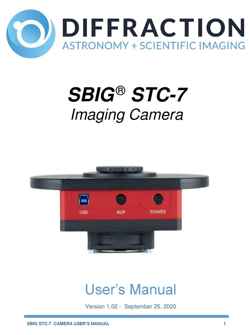
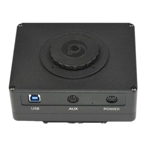
Diffraction SBIG Aluma AC Series User manual

SBIG ALUMA AC SERIES USER’S MANUAL
1
SBIG®Aluma AC Series
Imaging Cameras
User’s Manual
Version 1.0 - October 02, 2020

SBIG ALUMA AC SERIES USER’S MANUAL
2
This equipment has been tested and found to comply with the limits for
a Class A digital device, pursuant to part 15 of the FCC Rules. These
limits are designed to provide reasonable protection against harmful
interference when the equipment is operated in a commercial
environment. This equipment generates, uses, and can radiate radio
frequency energy and, if not installed and used in accordance with the
instruction manual, may cause harmful interference to radio
communications. Operation of this equipment in a residential area is
likely to cause harmful interference in which case the user will be
required to correct the interference at his own expense.
Industry Canada Compliance Statement
This Class A digital apparatus complies with Canadian ICES-003.
European Union
This product has been tested and found to comply with the limits for
Class A Information Technology Equipment according to CISPR
22/European Standard EN 55022. Warning: This equipment is
compliant with Class A of CISPR 32. In a residential environment this
equipment may cause radio interference.
Visit us at:
http://diffractionlimited.com
and
http://forum.diffractionlimited.com/
Diffraction Limited
59 Grenfell Crescent, Unit B, Ottawa, ON Canada, K2G 0G3
Telephone: 613-225-2732
Fax: 613-225-9688
© 2020 Diffraction Limited. All rights reserved. Cyanogen Imaging®, SBIG®, and Aluma® are
registered trademarks of Diffraction Limited. StackPro, SmartCooling, ST-4, MaxIm DL, and
MaxIm LT are trademarks of Diffraction Limited. GSENSE4040, GSENSE4040BSI, and
GSENSE2020BSI are trademarks of Gpixel. Windows is a registered trademark of Microsoft
Corporation. Macintosh is a registered trademark of Apple Corporation. The Linux trademark is
owned by Linus Torvalds. Ubuntu and Canonical are registered trademarks of Canonical Ltd. All
other trademarks, service marks, and trade names appearing in this guide are the property of
their respective owners.

SBIG ALUMA AC SERIES USER’S MANUAL
3
SBIG Aluma AC Series User’s Manual
Table of Contents
SBIG Aluma AC Series Imaging Cameras ................................ 5
1 –Installation............................................................................. 9
1.1 Supplied Components ................................................................................ 9
1.2 Installing the Software.............................................................................. 10
1.3 Installing the Hardware............................................................................. 11
1.4 Connecting the Water Hoses.....................................................................12
1.5 Testing the Camera....................................................................................13
2 –Operating the Aluma Camera with MaxIm LT .................. 14
2.1 Connecting the Aluma AC Series camera to MaxIm LT.......................... 14
2.2 Basic Imaging Procedure ......................................................................... 18
2.3 StackProTM Subexposure Function.......................................................... 20
2.4 Readout Modes ......................................................................................... 22
3 –Image Calibration ............................................................... 23
3.1Dark Frame Calibration............................................................................. 24
3.2Flat-Field Frame Calibration......................................................................26
3.3Understanding Calibration Groups.......................................................... 28
3.4Calibrating and Combining Images.......................................................... 29
4 –Accessories ........................................................................ 32

SBIG ALUMA AC SERIES USER’S MANUAL
4
Appendix A: SBIG Aluma AC Series Camera Details ........... 33
A-1 Connector pinouts ................................................................................... 33
A-2 Aluma AC Series Specifications.............................................................. 35
Appendix B: Maintenance ...................................................... 37
B-1 Cleaning the filters and sensor window ................................................. 37
B-2 Regenerating the desiccant .................................................................... 38
B-3 Updating the camera drivers and firmware ........................................... 39
Appendix C: Troubleshooting ................................................ 41
Appendix D: Technical and Warranty Support .............................42
Appendix E: Compatible software products.................................. 43
Appendix F: Concepts and Terminology ........................................ 44
IMPORTANT!
Please read this guide thoroughly before installing and
operating your new SBIG Aluma AC Series camera. It is
important to fully understand and follow all installation,
operation, and maintenance procedures as stated to ensure
proper functionality. Failure to do so may affect your
warranty!

SBIG ALUMA AC SERIES USER’S MANUAL
5
SBIG Aluma AC Series Imaging Cameras
The SBIG Aluma AC Series represents the state-of-the-art in advanced
scientific CMOS cameras for astronomical imaging systems. The SBIG
Aluma AC4040 and AC4040BSI utilize the Gpixel GSENSE4040 and
GSENSE4040BSI scientific CMOS sensors with 16.8 million 9 micron
pixels, arranged in a 4,096 x 4,096 array almost 37 mm square. The
SBIG Aluma AC2020BSI uses the Gpixel GSENSE2020BSI scientific
CMOS sensor featuring smaller 6 um pixels, for a total of 4.2 million
pixels in a 2,048 x 2,048 array. The BSI versions are Back-Side
Illuminated, for the highest available quantum efficiency.
Primary design features include:
High Quantum Efficiency
Our previous flagship CCD camera, the STX-16803, had very good
peak quantum efficiency at 60%. The Aluma AC4040 improves on
this significantly. The standard Front-Side Illuminated (FSI) model
has a peak Quantum Efficiency (QE) of 74%, and features a much
broader peak that is almost flat through the visible spectrum –from
450 nm through to over 900 nm. In practice, the overall sensitivity
of the Aluma AC4040 is therefore much higher than its CCD
predecessor. The FSI camera is available with a Grade 2 sensor or a
premium Grade 1 sensor with fewer pixel defects.

SBIG ALUMA AC SERIES USER’S MANUAL
6
For the most demanding applications, the Aluma AC4040BSI
features a windowless Back-Side Illuminated (BSI) sensor, which
has an incredible peak QE of 95%. In addition the premium BSI
sensor features significant UV sensitivity beyond 250 nm, and
excellent near IR sensitivity.
The Aluma AC2020BSI is only available with the Back-Side
Illuminated (BSI) sensor and also boasts a peak QE of 95%.

SBIG ALUMA AC SERIES USER’S MANUAL
7
StackPro™
The Aluma AC Series scientific CMOS cameras features StackPro™,
a revolutionary feature that performs image stacking inside the
camera.
CMOS sensors often have more limited well depth and bit depth
than their CCD predecessors. At the same time, the modern CMOS
sensors have much lower read noise than the equivalent CCD. This
low read noise can be used to advantage, by stacking many shorter
exposures to achieve the same final result. This does however result
in a lot of extra disk usage and post-processing.
StackPro™ performs the stacking automatically, inside the
camera. It automatically subdivides your exposure into up to 16
individual subexposures, and stacks them inside the camera prior
to download. Stacking can also be used as an alternative to HDR
mode.
HDR Mode
The Aluma AC Series sensors are capable of operating in High
Dynamic Range (HDR) mode, where high-gain and low-gain images
are read out simultaneously. Our included MaxIm LT software
features an HDR merge feature, which greatly simplifies the process
of producing clean, highly-linear images.
Superior Cooling
Proven pin heatsink design shared with our industry leading STX
series cameras gets the heat out while producing very little
vibration. Our SmartCooling™ function provides intelligent two-
stage thermoelectric temperature regulation to 0.1 degrees C for
high calibration stability, enabling a 40oC below ambient
temperature delta.
For high ambient temperature environments, the liquid cooling
option enables even higher thermal reduction performance to
minimize dark current further.
User-rechargeable Desiccant
SBIG pioneered the incorporation of a high-tech user-replaceable
cartridge with ceramic filter and molecular sieve desiccant. Unlike
competing cameras, which require factory service when their
chamber desiccant eventually saturates out, the user can easily
recharge the desiccant. This eliminates the need for costly service –
not to mention the associated down-time and shipping costs. This
feature is especially important in high-humidity locations.

SBIG ALUMA AC SERIES USER’S MANUAL
8
Electronic and Mechanical Shutters
The GSENSE CMOS sensor has an electronic rolling shutter. In
addition the Aluma AC Series cameras include a mechanical shutter
to enable convenient dark-frame subtraction for optimal
performance and sensitivity. This is essential for remote/robotic
operation.
USB 3.0 Interface
The Aluma AC Series cameras utilize a USB 3.0 interface port for
high-speed image downloads. For installations where longer cable
lengths are required, the port is also fully compatible with USB 2.0.
AUX Port
The Aluma AC Series cameras have a convenient auxiliary control
port (also known as an I2C AUX port), which controls the filter wheel
and provides optional external trigger interfaces. Unlike older SBIG
models, the AUX port is not used for adaptive optics AO-X control,
as this function is now handled by the optional SBIG StarChaser
SC-3 off-axis guiding camera.
MaxIm LT Software
All SBIG cameras come with our MaxIm LT software. MaxIm LT is a
special version of our venerable MaxIm DL software that provides
complete control of your camera, filter wheel, and autoguider, plus
advanced image processing capabilities. If you wish you can
upgrade to MaxIm DL Pro to get complete observatory integration
and even more processing and analysis capabilities.

SBIG ALUMA AC SERIES USER’S MANUAL
9
1 - Installation
1.1 Supplied Components
Camera
Your Aluma AC Series camera is provided in a deluxe foam-lined hard
shell protective case. Observe proper handling procedures for sensitive
electronic equipment and unpack the contents carefully in a clean, dry,
static-free area. Inspect the contents to ensure all components are
present and in good order. The kit includes:
Aluma AC Series monochrome imaging camera
Installed desiccant plug
STX Style Adapter Plate - 3.5" OD Dovetail and 3x24 TPI threaded
interface (an optional 3" diameter adapter is also available - Part
number: ACC09)
2” Nosepiece adapter
6-32 front panel screw mounts
Camera dust cap
Power supply:
o+12V DC 8A power adapter (60005B)
oPower cable with USA, European, or Australian plug (specified
on ordering), or
USB flash drive
Ferrite snap-on chokes (2) to reduce radio frequency interference
USB 3.0 cable, 12 feet (3.7 meters)
MaxIm LT software
7/64” (0.109") Allen key

SBIG ALUMA AC SERIES USER’S MANUAL
10
1.2 Installing the Software
The MaxIm LT imaging application allows you to operate your Aluma AC Series
camera using a Windows computer and is included with your purchase. Device
drivers are provided for the Windows, MacOS, and Linux operating systems.
System requirements
The following hardware and software is required for MaxIm LT:
MS Windows (applicable versions: 7, 8, 8.1, 10)
Recommended minimum memory size: 2 GB or larger.
Processing large arrays or opening multiple images simultaneously may
require correspondingly more memory.
Disk space: 100 MB for program installation
Video display: 1024x768, 16-bit color or higher
Mouse
Internet browser
Windows installation
1. Go to the Registration page on the Diffraction Limited website at:
https://diffractionlimited.com/maxim-lt-registration
2. Enter the requested information and serial number to register for the
MaxIm LT application. Use your camera’s serial number for this. If your
camera is authorized for a free license you will be automatically emailed a
license key.
3. Insert the supplied flash drive into an available USB port.
4. Open Windows Explorer and navigate to the flash drive’s root folder.
5. Double-click Launcher.exe, then click DL Config to install the application.
When the installation is completed, launch DL Config.
6. Return to the Launcher and click the Install MaxIm DL/MaxIm LT button.
Follow the onscreen instructions to install the Maxim LT application and
then enter the license key you received when prompted.
NOTE:
To enter your license key properly, you must select all the text from the
email you receive and copy it to the clipboard. You then start MaxIm LT and
open the Enter License dialog. The license key will be entered automatically
–there is no need to paste it since MaxIm LT finds it on the clipboard and
pastes it for you.
7. Click OK to finish. You can then proceed to the next section to install your
hardware.

SBIG ALUMA AC SERIES USER’S MANUAL
11
1.3 Installing the Hardware
Perform the following procedure to prepare your Aluma AC Series
camera for use.
1. Install the ferrite snap-on chokes at convenient positions along both
the USB cable and the DC power cable, preferably close to the
camera ends of these cables. Open a choke and lay the cable into the
channel, then snap the choke halves together.
2. Attach the cabling:
CAUTION:
Never “hot plug” the cables into or from the units. Always
disconnect power before connecting or disconnecting any cables.
Attach the USB cable between the USB connector and your
computer.
The AUX connector is used for various accessories, such as a filter
wheel. If you have such an accessory do not connect it at this time
for initial testing of the camera.

SBIG ALUMA AC SERIES USER’S MANUAL
12
Attach the power supply cable between the POWER connector and
the power supply. Thread the connector backshell onto the
camera to lock it in place.
Do not turn the power supply on yet.
The camera is now ready to be powered up and tested. Refer to:
Section 1.5 Testing the Camera.
1.4 Connecting the Water Hoses
The Aluma AC Series cameras are equipped with a heat exchanger that
allows water circulation if your environmental conditions require
additional cooling of the sensor. The camera may be operated with or
without water circulation. No special steps are necessary to use water
cooling other than connection to a water supply. The camera comes with
two water hose fittings that accept hoses with an inside diameter of ¼-
inch. The hoses should be clamped to the fittings to prevent leaking.
Very little water pressure is needed for the additional cooling. Only
enough pressure to maintain a constant flow is required to get the
maximum benefit from the water circulation.
It is usually not necessary to cool the water below ambient temperature
with ice or refrigeration, but this can be done provided that you monitor
the dew point. Water at ambient temperature is an effective heat
conductor and a constant flow of water will carry away enough heat
from the heat exchanger that further cooling of the water supply will
result in very little gain. Cooling the water supply too much may also
cool the camera well below the dew point which can allow moisture to
form on the inside surface of the case or the outside surface of the
sensor chamber window.
Water can be supplied to the camera from a faucet, or if that is
unavailable, a small 12-volt pond pump and water bucket can also be
used. These types of pumps and the required tubing can be purchased
at most hardware stores for this purpose. The water inlet and outlet
connections on the camera body are reversible –the water can flow in
either direction.

SBIG ALUMA AC SERIES USER’S MANUAL
13
1.5 Testing the Camera
Once MaxIm LT is installed and the camera hardware is connected,
Diffraction Limited recommends that you perform a simple bench test of
the system. Do this before mounting your camera on your optics.
You should read Chapter 2 to familiarize yourself with the basic
software connection and operating instructions prior to performing this
test.
Proceed with the bench test as follows:
1. Verify that all cabling is properly connected.
2. Apply power to the camera.
NOTE:
The Aluma AC Series camera comes with a power supply capable of
operating from 90 to 264 VAC. Actual power requirements are +12
VDC at 8A maximum.
Refer to Appendix A-1 Connector pinouts for connector details if you
need to create a custom power cable.
3. Open MaxIm LT and connect to the camera by following the
procedure in Section 2.1 Connecting the Aluma AC Series camera to
MaxIm LT.
4. Take a set of exposures. Set your exposure length to a very short
duration to avoid saturation if you are conducting this bench test
under bright lighting conditions. Alternatively, you can limit the
amount of light entering the camera by covering the sensor opening
using a piece of cardboard with only a small hole in it.
5. If your testing is successful, you are now ready to mount the camera
to your optical device.

SBIG ALUMA AC SERIES USER’S MANUAL
14
2 - Operating the Aluma camera with MaxIm LT
The MaxIm LT application allows full configuration and control of the SBIG
Aluma AC Series cameras. Calibrating files, automating imaging sequences,
logging, and various image processing tasks can all be performed. Please note
however that since MaxIm LT and MaxIm DL both share the same Help file, not
all features detailed in that file will be enabled in MaxIm LT. Full feature
access requires MaxIm DL Pro.
The procedures in this chapter are intended as a basic introduction to
connecting and operating the Aluma hardware. Consult the Help file for further
information on specific parameters, detailed procedures, and various tutorials.
2.1 Connecting the Aluma AC Series camera to MaxIm LT
The following is the basic MaxIm LT procedure used to configure and connect
to the Aluma camera. Launch the MaxIm LT application.
1. Click the Camera Control icon or press Ctrl-W to open the Camera
Control form and click the Setup tab.

SBIG ALUMA AC SERIES USER’S MANUAL
15
2. Click the Setup Camera button under Camera 1. The Setup DL Imaging
form opens.
3. Click the Camera Model drop-down. Select DL Imaging.
4. Ensure that the AO selector parameter is set to Off.
5. Click the Advanced button. The DL :: Config form opens.
This form allows you to check camera parameters and also to perform
firmware updates and additional camera configuration.

SBIG ALUMA AC SERIES USER’S MANUAL
16
Your camera should appear under Devices. The camera serial number is
displayed so you can recognize it if there are multiple cameras in your
system. Click on the camera you wish to use and its information will
appear under Camera Info. Click OK.
Various camera parameters will auto-populate the display fields in the
form. The default settings should be fine for your initial connection -
reconfigure them if required. Full details on these parameters are available
in the MaxIm DL Help file and at:
https://diffractionlimited.com/help/maximdl/SBIG_Gen_3.htm
Click OK to confirm your camera selection and close the DL :: Config form.
6. Click OK to accept the settings and close the Setup DL Imaging form.
7. Click the Options button under Camera 1. The Options form opens.
8. Configure any of the optional camera parameters if required or use the
default values as a starting point.
NOTE:
Access camera from separate thread and Access filter wheel from separate
thread must both be selected for both Camera 1 and Camera 2 (if used).
9. Click OK to accept the settings. The Options form closes and you are
returned to the Camera Control form.

SBIG ALUMA AC SERIES USER’S MANUAL
17
10. If you have installed a filter wheel, perform steps 11 through 13. Otherwise
go to step 14.
11. Click the Setup Filter button under Camera 1. The Setup DL Imaging+FW
form opens.
12. Click the Filter or Controlling Camera Model drop-down and select
DL Imaging+FW. The default filter positions and names are displayed.
13. Click OK to accept the settings. The Setup DL Imaging+FW form closes and
you are returned to the Camera Control form.
14. Leave Camera 2 set to No Camera.
15. Click the Connect button to establish camera communications.
16. Enable the camera cooler by clicking the On button.
17. Click the Cooler button under Camera 1. The Set Camera Cooler form
opens.
18. Set the desired cooler temperature (in degrees Celsius) and click OK. The
Set Camera Cooler form closes.
19. The Aluma AC Series camera is now connected and ready to begin
imaging.
Note that the next time you open MaxIm LT, your option selections will
automatically appear in the Setup DL Imaging form.

SBIG ALUMA AC SERIES USER’S MANUAL
18
2.2 Basic Imaging Procedure
After setting up your camera as stated in Section 2.1 Connecting the Aluma AC
Series camera to MaxIm LT, the Expose tab in the Camera Control window
allows you to set the exposure parameters and initiate imaging. This procedure
details the basic approach to imaging with an Aluma AC Series camera.
1. Click the Expose tab. The form displays the following:
2. Click the Options menu and select Camera Settings. Applicable settings for
the Aluma AC Series camera include:
Use Ext. Trigger (This is not selected by default. Refer to Appendix A-1
Connector pinouts for information on using the Trigger In/Trigger Out
function.)
Fan Speed drop-down list
Auto Fan Speed
Enable Status LED (Normally enabled. Turn this off to disable the LED
on the side of the camera for darkness.)
Subexposure Duration (refer to 2.3 StackProTM Subexposure Function
for details)
Configure the parameters as required and click OK to accept.

SBIG ALUMA AC SERIES USER’S MANUAL
19
3. Configure the parameters as follows:
Click on the Camera 1 radio button.
Exposure Preset: The presets allow you to quickly configure the
exposure parameters for different types of imaging. Use the Standard
exposures option for this introductory imaging procedure.
Readout Mode: There are five available readout modes: High Gain, Low
Gain, StackPro High Gain, StackPro Low Gain, and HDR.
Frame Type: Light
Filter Wheel: If a filter wheel is installed, select the desired filter.
X Binning: 1
When binning greater than 1 is selected, the electronic charge from
groups of adjacent 2x2 pixels is electronically summed in the camera
before readout. This process effectively increases sensitivity, but at the
cost of lower spatial resolution. Binning of the X and Y axis of the
sensor can be configured individually.
Y Binning: Same or 1
Subframe: Deselect the On checkbox. This will ensure that you capture
the entire frame, rather than just a part of it.
Seconds: Set the desired exposure time in seconds. You can use the
scroll arrows or type in a value into the field. Exposures of less than a
second must be entered as decimal values.
4. Click the Options arrow. A list of choices is displayed. This menu is used to
access and configure a number of imaging parameters to customize your
imaging requirements.
For this introductory imaging procedure, set the following:
Click on No Calibration.
Click on Set Image Save Path. The Select Folder form opens. Use this to
specify where to save your images.
Click on Exposure Delay. This sets a delay time (in seconds) prior to the
start of an exposure. If you are taking a continuous sequence, this
delay will be applied between each image.
Click on Show Tool Tips if you want to display pop-up tips on form
options.
5. To begin an individual exposure, click the Single radio button and then the
Start button. You can end the exposure manually at any time by pressing
Stop. You must save this image manually if you want to keep it.
6. To begin a continuous sequence of identical exposures, click the
Continuous radio button and then the Start button. The sequence only
ends when you press Stop. This mode is generally used for focusing and
framing purposes, and the acquired images are not saved.
7. To configure a custom sequence of exposures, click the Autosave button.
The Autosave Setup form opens.

SBIG ALUMA AC SERIES USER’S MANUAL
20
For this introductory imaging procedure, set the following:
Autosave Filename: Enter the base filename (e.g. “Area A”) you want to
use for the sequence of images. Each image file taken will use this
name, appended with an individual frame number, for example,
"Area A-001.fit".
Dither: Off
Delay First: Specify a delay time (in seconds) prior to taking the first
exposure, if desired.
Delay Between: Specify a delay time (in seconds) between exposures, if
desired.
Click the Slot 1 button and configure each of the parameters on the line
as you require. The Repeat parameter allows you specify how many of
these particular exposures will be taken. An optional Suffix can also be
automatically applied to the end of the filename to aid you in
identifying subgroups of images later on. For example, if you add a
suffix of "a", this will produce a filename such as "Area A-001a.fit". If
you use only one imaging slot for your custom sequence then you don’t
really need a suffix. However, if you set up multiple slots then you
must add a suffix, and each suffix must be unique. You can configure
up to 32 slots when setting up an Autosave sequence.
Click OK when you are finished configuring the sequence.
8. To begin the custom sequence, ensure that the Autosave radio button is
selected and click Start. You can end the Autosave sequence at any time
prior to its completion by pressing Stop.
2.3 StackProTM Subexposure Function
The subexposure function allows you to increase the effective dynamic range of
the camera. It works by taking a series of shorter exposures, and then
numerically summing them internally to the camera. Since the Aluma AC
Series cameras have very low read noise, this greatly increases the camera's
dynamic range while it only modestly increases the total read noise in your
image. Due to the fast readout speed of the CMOS sensor, the extra time
required is negligible.
As an example, when using the Aluma AC4040 (FSI) in High Gain mode, the
camera can record about 3,300 photoelectrons before saturating,
corresponding to a readout value of 4,095 (12 bits). The read noise is
approximately 3.7 electrons.
If you mathematically stack 16 individual High Gain exposures the total
number of photoelectrons that can be recorded increases 16X, but the readout
noise only increases 4X. The read noise is now 14.8 electrons, and the stacked
exposure can record 52,800 electrons, corresponding to a readout value of
65,535 (16 bits).
This manual suits for next models
1
Table of contents
Other Diffraction Digital Camera manuals
