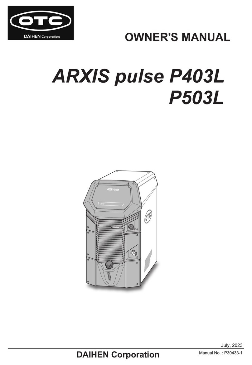
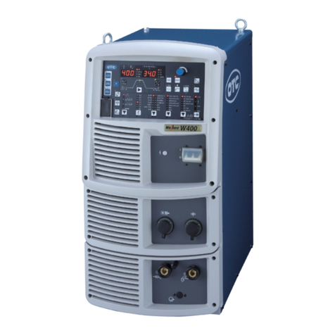
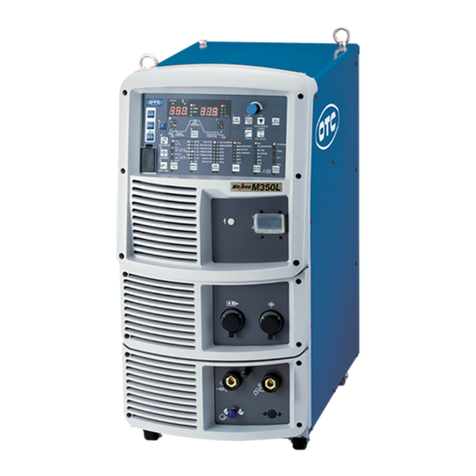
Daihen OTC XD350 User manual

Service Manual No.C0056-1
SERVICE MANUAL
DAIHEN DC arc welding power source
350/500
CPXD- 350 C0056
CPXD- 500 C0052
DAIHEN Corporation WELDING PRODUCTION DIVISION
Aug.11.2006
CO
2
/MAG
DYNA AUTO
NOTE: Ther is a case that contents of thes service
munual is different from the latest information by
revision after product shipment. Use the owner’
s
manual of this procuct together.

CPXD-350,500 SERVICE MANUAL
- 1 -
1. Caution in maintenance
1.1 To avoid electric shock and accident
When checking internal power source, turn off the primary side of line disconnect switch and the
control power source switch, wait more than 3 minuets and check that the built-in cooling fan stops
completely then carry out checking. And be careful not to turn on these switches by mistake during
check.
Be in particular careful where the place indicated “High voltage danger”.
According to measuring instrument oscilloscope and so on the like, terminal for measurement and
case are connected electrically. When checking internal welding machine by these measuring
instrument, be careful not to cause an electric shock accident.
1.2 Handling of printed circuit board
(1) Do not to touch the potentiometer which fixed by white pen on the printed circuit board.
It cause to trouble in welding machine.
(2) Insert all printed circuit board certainly to take a lock of circuit board support for attachment.
(3) Insert connector with matching connector number or wiring number certainly to take a lock.
Do not to pull the wire when pulling connector. Carry out pulling and inserting connector after
turning off the power source switch.
(4) Do not leave the place where static electricity is easy to generate because CMOS-IC that is poor
at static is used.
(5) Reduce the number of times as much as possible that pulling and inserting connector and
adjustment of the potentiometer.
Welding power source
Input power
Oscilloscope

CPXD-350,500 SERVICE MANUAL
- 2 -
1. Caution in maintenance (continued)
1.3 Handling of main circuit component
(1) When attaching thyristor module to heat sink, apply micro computer and fix by designated
torque.
(2) Use torque of specific value also to clamp terminal.
1.4 In case of insulation resistance test
When measuring insulation resistance and testing withstand voltage, follow the steps below.
(1) Disconnect the primary cable to the switch box and welding cable for isolating welding power
source.
(2) Remove earth cable (line No.80 which is between C2 and C3) of output terminal from the case.
Then insulate this earth cable due to not touch the case.
(3) Short-circuit the contact interval (line No. 1, 4) of magnet switch.
(4) Turn on the control power source S1.
Be sure to reconnect the cables after carrying out measurement of insulation resistance and
withstand voltage test.
1.5 Only to check operation of sequence
When only to check operation of sequence, follow the steps below.
(1) Turn off the control power source.
(2) Take off CN23, 24 on PCB C0045Q.
(3) Turn on the control power source and check the operation.
Be sure to reconnect the cables after checking.
1.6 Investigate the WARNING cause
There are any WARNING in the welding machine, narrow down a cause refer to” Welding error
table” and “Troubleshooting”. Then settle the WARNING refer to “Checking method for WARNING”

CPXD-350,500 SERVICE MANUAL
- 3 -
2. Function of each printed circuit board
2.1 Function of printed circuit board and mounting position
Printed circuit board
PART No. Function Mounting position
C0056P
(CPXD-350)
C0052P
(CPXD-500)
・Microcomputer control
Sequence control
Constant voltage control
Welding control
WARNING protection
Input voltage change revision
50/60Hz identification
・Zero-cross detective circuit
・Input voltage detective circuit
・Primary voltage detective circuit
・Emergency stop detective circuit
Fan frame
(CPXD-350)
Chassis
(CPXD-500)
C0045Q
(Common in all models)
・Power source circuit
・Governor circuit
・Thyristor drive circuit
・Short-circuit detective circuit
・Relay circuit
P10174X
(Common in all models)
・Remote control one-line circuit
・CM-2301 / 2302 reshuffling
“C0056P and C0052P” is showing to “C0056P” in page following than this.
When using the other type of machine, read the manual with rearranging “C0056P” to “PCB No. suitable
for the type of machine”.

CPXD-350,500 SERVICE MANUAL
- 4 -
2. Function of each printed circuit board (continued)
2.2 Operation of check terminal on printed circuit board
T : is measured by tester
S : is measured by oscilloscope
2.2.1 Check terminal on printed circuit board PC0056P
No. Signal name Explanation
CH1 0V Ground
CH2 + 5V T: CH1-, CH2+ +5V
CH3 - 15V T: CH1+, CH3- +15V
CH4 + 15V T: CH1-, CH4+ +15V
CH5 Feed quantity setting T: CH1-, CH5+
Voltage changes between 5 from 1V according to current knob of
remote control.
CH6 SCR trigger 3 S: CH1-, CH6+
Pulse waveform such as the figure below.
CH7 SCR trigger 2 S: CH1-, CH7+
Pulse waveform such as the figure below. (Same as CH6)
CH8 SCR trigger 3 S: CH1-, CH8+
Pulse waveform such as the figure below. (Same as CH6)
CH9 Zero-cross 1 S: CH1-, CH9+
Pulse waveform such as the figure below.
CH10 Zero-cross 2 S: CH1-, CH10+
Pulse waveform such as the figure below. (Same as CH9)
CH11 Zero-cross 3 S: CH1-, CH11+
Pulse waveform such as the figure below. (Same as CH9)
CH12 Input voltage T: CH1-, CH12+
When rated input voltage, become 2.6V(CPXD-350) and 4,0V
(CPXD-500).
It changes in proportion an input voltage.
CH13 Output current T: CH1-, CH13+
Voltage changes between 10 from 0V according to output
current. Voltage is 10V when current is 1000A.
CH14 Current detection T: CH1-, CH14+
When output current is detected, voltage is 0V and when it is not
so, 5V.
+15V
0V
60μs
10ms: 50Hz
8.3ms: 60Hz
+5V
0V
400μs
10ms: 50Hz
8.3ms: 60Hz

CPXD-350,500 SERVICE MANUAL
- 5 -
2. Function of each printed circuit board (continued)
2.2 Operation of check terminal on printed circuit board (continued)
2.2.2 Check terminal on printed circuit board C0045Q
No. Signal name Explanation
CH1 0V Ground
CH2 +5V T: CH1-, CH2+ +15V
CH3 -15V T: CH1+, CH3- +15V
CH4 +15V T: CH1-, CH4+ +15V
CH5 +24V T: CH1-, CH5+ +24V
CH6 24V(supporting wire) T: CH1-, CH6+ +24V
CH7 Governor SCR-K S: CH1-, CH7+
Pulse waveform such as the figure below.
CH8 TS T: CH1-, CH8+
+15V (TS is OFF), 0V (TS is ON)
CH9 GAS T: CH1-, CH9+
+24V (When gas is stopping), 0V (When gas is releasing).
CH10 Short-circuit detection
T: CH1-, CH10+
15V (When short-circuit), 0V (When outputting voltage)
2.2.3 Check terminal on printed circuit board P10174X
No. Signal name Explanation
CH1 0V Ground
CH2 +15V T: CH1-, CH2+ +15V
CH3 -15V T: CH3-, CH1+ +15V
CH4 Missing number
CH5 Exchanging signal S: CH1-, CH5+
Pulse waveform such as the figure below.
CH6 TS / WV S: CH1-, CH6+
Pulse waveform such as the figure below.
CH7 Inching / WC S: CH1-, CH7+
Pulse waveform such as the figure below.
CH8 Vref T: CH1-, CH8+ 0~+5V
CH9 Iref T: CH1-, CH9+ 0~+5V
0V
Motor is stopping
Motor is rotating
0V
-50V
10ms: 50Hz
8.3ms: 60Hz
Changed by W.V knob
Changed by torch switch
OFF: about 0V / ON: -15V
Changed by W.V knob
Changed by inching switch
OFF: about 0V / ON: -15V
15V
-15V
15V
0V
0V
-
15
V
15V
0V
-
15
V
CH5
CH6
CH7

CPXD-350,500 SERVICE MANUAL
- 6 -
2. Function of each printed circuit board (continued)
2.3 Adjustment resistance of printed circuit board and meaning of jumper switch.
Adjustment resistance of printed circuit board C0056P
No. Signal name Explanation
R13 Pre-flow time Adjust pre-flow time. Normal position is full of turning left.
R14 Post-flow time Adjust post-flow time. Normal position is full of turning left.
R15 Anti-stick time Adjust anti-stick time. Normal position is full of turning left.
R16 Anti-stick voltage Adjust anti-stick voltage. Normal position is full of turning left.
R17 Output adjustment For fine adjustment of ignition phase.
Normal position is full of turning left.
R18 Crater repetition
period
(Only for XD500, 600)
Adjust crater repetition period. Normal position is full of turning left.
R70 Slow-down speed Adjust slow-down speed.
Jumper switch of printed circuit board C0056P
No. Signal name Explanation
S1-1 Simple substance
inspection
Use for simple substance inspection of printed circuit board.
Use it in regular OFF.
S1-2 Initial current Initial current function is possible to use with turning to ON when
crater is ON or REPEAT.
S1-3 Wire feeder exchange
function
Set it suitable for wire feeder. Refer to page 19 about setting.
S1-4 Extra heating function Turn to ON, and MS is ON, regular voltage outputs to AC100V
receptacle.
Turn to OFF, MS becomes OFF after the welding end in about five
minutes
S1-5 Wire feeder exchanging
function
Set it suitable for wire feeder. Refer to page 19 about setting.
S1-6 Including inspection Turn to ON, checking whether switch of remote control or panel is
operating normally is possible. In this time , welding is out of use.
S1-7 Out of use Use it in regular OFF.
S1-8 Select ammeter Set it suitable for type of machine.
CPXD-350 : OFF
CPXD-500 : ON

CPXD-350,500 SERVICE MANUAL
- 7 -
2. Function of each printed circuit board (continued)
2.3 Adjustment resistance of printed circuit board and meaning of jumper switch (continued)
Adjustment resistance of printed circuit board C0045Q
No. Signal name Explanation
R11 Max. feed speed
adjustment
Mode1, current knob is Max. position and connecting with CM-2302:
170 rpm (Setting is done at the shipment)
Jumper switch of printed circuit board C0045Q
No. Signal name Explanation
J1 Short-circuit
detective terminal
Normal side is +② terminal. +① terminal is out of use.
Adjustment resistance of printed circuit board P10174X
No. Signal name Explanation
R38 Vref fine adjustment
Use it to adjust when the voltage scale of remote control deviates
from welding voltage greatly.
Change J1 to “ADJ” when adjusting.
It becomes lower with turning to an anti-clock and becomes highly
with turning to a clock.
R39 Iref fine adjustment Use it to adjust when the current scale of remote control deviates
from welding current greatly.
Change J2 to “ADJ” when adjusting.
It becomes lower with turning to an anti-clock and becomes highly
with turning to a clock.
Jumper switch of printed circuit board P10174X
No. Signal name Explanation
J1 Vref
Changing
adjustment method
Change adjustment method of output voltage of Vref.
It becomes normal value fixation with turning to “FIX” and adjustment
with R38 is become possible with turning to “ADJ”.
Normal position is “FIX”.
J2 Iref
Changing
adjustment method
Change adjustment method of output voltage of Iref.
It becomes normal value fixation with turning to “FIX” and adjustment
with R39 is become possible with turning to “ADJ”.
Normal position is “FIX”.

CPXD-350,500 SERVICE MANUAL
- 8 -
2. Function of each printed circuit board (continued)
2.4 Check point position of each printed circuit board
2.4.1 C0056P
C0056P

CPXD-350,500 SERVICE MANUAL
- 9 -
2. Function of each printed circuit board (continued)
2.4 Check point position of each printed circuit board (continued)
2.4.2 C0045Q
C0045Q

CPXD-350,500 SERVICE MANUAL
- 10 -
2. Function of each printed circuit board (continued)
2.4 Check point position of each printed circuit board (continued)
2.4.3 P10174X

CPXD-350,500 SERVICE MANUAL
- 11 -
3. Troubleshooting
3.1 WARNING lamp
When an error occurs, warning lamps on the front panel LED turns on or flashes, then the welding
power source automatically stops. In this case, check the errors distinction by LED is possible.
●:OFF, ○:Light, ◎:Flash, △:Flash two times
Error
No. Error Front panel
LED
LED 1
(red light)
LED 2
(green light)
① Power supply frequency ○ ○ ○
② Temperature ○ ○ ●
③ Input overvoltage ○ ● ○
④ Shortage of input voltage ○ ● ●
⑤ CO2/MAG welding mode switch error ◎ ○ ○
⑥ Error before starting welding ◎ ● ●
⑦ Gas check ◎ ● ○
⑧ Output overcurrent ○ ● ○
⑨ Microcomputer △ ○ ●
⑩ Output voltage △ ● ○
⑪ Current detection △ ● ●
① Power supply frequency
When the POWER CONTROL switch on the front panel is turn on at unstable power supply
frequency, the warning lamp comes on and the welding power source continues to stop operation. In
this case, turn off the power switch and turn on again to cancel the error.
② Temperature error
When the duty cycle exceeds the rated duty cycle or the temperature exceeds 40˚C, the WARNING
lamp flashes and the welding power source stops automatically. In this case, wait until the fan stops,
with the CONTROL POWER switch turned on. When starting the welding operation again, use the
welding machine lower the duty cycle or the welding current.
③ Input over voltage error
When input voltage goes beyond 460V, the WARNING lamp lights up and the welding power source
stops automatically. Disconnect the CONTORL POWER switch and measure the input voltage with
such a measuring instrument as a tester to check to make sure if excessively high voltage is not
output. To eliminate the error, turn on the CONTORL POWER switch again after removing a cause of
the error above.
④ Shortage of input voltage error
When input voltage falls below 320V, the warning lamp lights, then the welding power source
automatically stop operation. In this case disconnect the switch and confirm there is no failure, then
turn on the switch again.
⑤ CO2/MAG welding mode switch error
When unavailable mode numbers are set while pressing the CO2/MAG welding mode switch on the
front panel, the WARNING lamp flashes and the welding power source keep stopping.
In this case, setting back to the normal setting is removing abnormal.

CPXD-350,500 SERVICE MANUAL
- 12 -
3. Troubleshooting (continued)
3.1 WARNING lamp (continued)
⑥ Error before starting welding machine
When the CONTROL POWER switch is turned on while the TORCH switch is on, the warning lamp
flashes (Flash 1) and the welding power source keep stopping. Turn off the TORCH switch to cancel
the error.
⑦ Gas check error
When more than two minutes has passed while the GAS CHECK switch is turned to the CHECK side,
the warning lamp flashes (Flash 1), then the welding power source stops automatically. To cancel Gas
check error, set the GAS CHECK switch to WELD. (WARNING indication is same as Shortage water
pressure.)
⑧ Error in output over current
When more than two-seconds over current or short-circuit is continued, the warning lamp lights up
and welding machine automatically stops. In this case, turn off the CONTROL POWER switch and
make sure to see if welding current does not exceed the rated output current or contact between tip
and base metal or short-circuit of output (cables). To cancel this error, solve the cause of error, then
turn on the CONTROL POWER switch again.
⑨ Error in microcomputer
When an error is detected in microcomputer, the warning lamp flashes two times. After the warning
lamp flashes, the welding machine automatically stops.
⑩ Trouble of output voltage
When the TORCH switch is turned off and voltage on the output terminals presents, the WARNING
lamps flashes (Flash 2) and the welding machine automatically stop welding. In case of welding
same work piece with several welding machines, turn off the power switch and check whether wire or
torch cable contact with base metal or output cable of other welding machine. If there are some
contacts, make sure removing them and turn the switch on. If abnormal still exist, check to make
sure if main thyristor or an electromagnetic contactor is not broken by using a tester, after turning off
the POWER switch. To cancel this error, turn on the main power switch again after solving the cause
of the error. (If voltage on from outside, the welding machine automatically stop welding. This
WARNING is occurred the place there are plural power sources, check that not to contact with the
near side plus line of power source.)
⑪ Current detection error
Loose or breaking wiring between a hall element (CT) and a printed circuit board C0056P, warning
lamp lights up and welding power source automatically stops. In this case, turn off the POWER switch
and check for the trouble of wiring. After solving the cause of trouble, turn on the CONTROL POWER
switch again to cancel the error.

CPXD-350,500 SERVICE MANUAL
- 13 -
3. Troubleshooting (continued)
3.2 Check of main circuit parts
When check of main circuit parts, be caution “1.1 To avoid electric shock and accident” in particular.
And resistance value in the list is changed by internal resistance of tester (digital tester in particular)
that is used. So regard as it is standard.
3.2.1 Thyristor module
Tester red
(+)
Tester black
(+)
Measured
value(Ω)
K1 K2 ∞
G1 G2 ∞
A K1 ∞
K1 A ∞
A G1 ∞
G1 A ∞
G1 K1 20
K1 G1 20
A-G2, A-K2, A-G3, A-K3 are same as this list.
A is heat sink attachment side.

CPXD-350,500 SERVICE MANUAL
- 14 -
3. Troubleshooting (continued)
3.3 Welding error table
Error Cause Checkpoint
Complete connection of base metal and torch cable.
Fuse of input power disconnect switch. Complete
connection of input cables.
No WARNING lamp lights.
Control cable and socket.
No voltage applied between
torch and base metal.
Settings of this welding power source match wire
feeder and remote control. (Check the connections
of P10174X match wire feeder connected to this
welding power source.)
Fuse of input power disconnect switch. Complete
connection of input cable.
No WARNING lamp lights.
Control cable and socket.
Pressure lever of wire feeder.
No arc is generated.
Wire will not be fed.
Settings of this welding power source match wire
feeder and remote control. (Check the connections
of P10174X match wire feeder connected to this
welding power source.)
Settings of current and voltage.
Welding mode and wire diameter set.
Improper welding conditions
Distance between torch and base metal.
No insulator on surface of base metal.
Complete connection of base metal and torch cable.
Bad arc start
Incomplete power supply
Tip worn out.
Complete connection of base metal and torch cable. Incomplete power supply
Tip worn out.
Current, voltage, amount of gas flow and welding
speed.
Improper welding conditions
Welding mode and wire diameter properly set.
Pressure adjustment of wire.
Parts matching your wire diameter.
Hole of tip not damaged.
No built-up dusts in liner.
Wire not smoothly fed.
Conduit not too bent.
No oil on base metal. Dirty wire and base metal
No rust on wire.
Cap nut of gas hose not loosen. Air in shield gas
No holes in gas hose.
Unstable arc and
rough welding bead
Arc blow occurs. Taking measures to prevent arc blow

CPXD-350,500 SERVICE MANUAL
- 15 -
3. Troubleshooting (continued)
3.4 Troubleshooting
No. Trouble Cause Solution
Fan FM rotates
when CONTROL
POWER switch S1
turns on.
Trouble of PL1 lamp. Check the PL1.
Line disconnect switch (or
NF) is not turned on.
Check power box.
1
Main POWER lamp PL1
will not light.
Fan FM will not
rotate when
CONTROL POWER
switch S1 turns on.
Lack phase or poor
connection of input cable (U
or V phase)
Check the input cable.
Trouble of thermostat THP1. Replace thermostat
THP1.
Poor insertion of CN14 or
CN15 on PCBPC0045Q.
Completely insert CN14
or CN15 on C0045Q.
When turning on
CONTROL POWER
switch S1.
Short-circuit control cable of
wire feeder.
Check control cable. (TS
line)
Fan FM does not rotate. Refer No.3.
Excess of duty cycle. Observe the rated duty
cycle.
2
WARNING lamp PL3
(yellow light) lights up.
(Check of 3.1 is no
problem.)
During welding.
Overheat inside welding
power source.
Cool down after checking
the cause.
Main POWER lamp
PL1 does not light
up.
Refer to No.1.
-
Trouble of CONTROL
POWER switch S1.
Replace power switch
S1.
Blown fuse F1. After checking cause of
the trouble, replace the
fuse F1.
Trouble of fan FM. Replace the fan FM.
3
Fan FM will not rotate
when turning on the
CONTROL POWER
switch S1. (On no
pre-heat function
setting, fan
automatically stops,
when welding machine
keeps to stop operation
while CONTROL
POWER switch turned
on.)
Main POWER lamp
PL1 lights up.
Trouble of P.C.B. (control
circuit.)
After checking C0056P
and C0045Q, replace
them if needed.
Trouble of P.C.B. (gas control
circuit.)
After checking C0056P
and C0045Q, replace
them if needed. 4
Shield gas does not stop.
Trouble of gas
electromagnetic valve SOL.
Replace SOL.
Discharge valve of gas
cylinder is closed. Or
shortage of gas pressure.
Open gas valve and
check gas pressure.
Trouble of gas
electromagnetic valve SOL.
Replace gas
electromagnetic SOL.
Blown fuse F1 on C0045Q. Replace F1 after
checking cause of the
trouble.
Trouble of electromagnetic
contactor MS.
Replace electromagnetic
contactor MS.
Trouble of P.C.B. (gas control
circuit)
After checking C0056P
and C0045Q, replace
them if needed.
Shield gas does not come
out, when S3 is set to
CHECK side.
Trouble of wrong connection
of P.C.B. (remote control
circuit)
After checking P10174X
and the wiring on this,
replace them if needed.
Trouble of torch switch TS. Replace the torch switch
TS.
5
Shield gas does
not come out
when torch
switch TS is
turned on. Fan
FM rotates and
WARNING lamp
PL3 is off.
Shield gas is generated,
when S3 is set to GAS
CHECK side. Breaking of control cable of
wire feeder or poor contact of
receptacle.
After checking the cable
and the receptacle (line
of torch switch), replace
them if needed.

CPXD-350,500 SERVICE MANUAL
- 16 -
3.4 Troubleshooting (continued)
No.
Trouble Cause Solution
Breaking of control cable of
wire feeder or poor contact of
receptacle.
After checking cable and
receptacle (line of feed motor),
replace them if needed.
Blown fuse F2. After checking causes of the
trouble, replace the fuse F2 if
needed.
Trouble of R2. After checking causes of the
trouble, replace the R2 if needed.
Trouble of SCR3.
After checking causes of the
trouble, replace the SCR3 if
needed.
Trouble of wire feed motor. Check the wire feed motor.
Trouble of P.C.B. (motor
circuit)
After checking C0056P or
C0045Q, replace them if needed.
6
Wire will not
be fed when
the torch
switch TS is
turned on.
When pressing the
Inching switch, wire will
not be fed.
Trouble of P.C.B. (remote
control circuit) or incorrect
connection.
After checking P10174X and the
wiring, replace them if needed.
Trouble of P.C.B. (control
circuit).
After checking C0056P or
C0045Q, replace them if needed.
Trouble of thyristor SCR1 and
2.
Replace by new thyristor SCR1
and 2.
Poor insertion of CN4, 23, 24
on C0045Q, and CN8 on
C0056P.
Completely insert the connectors.
7
Output voltage will not be generated
when torch switch TS is turned on.
Trouble of P.C.B. (remote
control circuit) or wrong
connection.
After checking P10174X and the
wiring, replace them if needed.
Trouble of thyristor SCR1 or 2.
Replace the thyristor SCR1 or 2 if
needed.
Trouble of hall element CT. Replace the current detector CT.
Check wire number [1]~[3],
[8]~[13], [17], [21]~[26].
Check the wiring.
8
Being out of control welding machine
causes large current flow.
Trouble of P.C.B. (control
circuit and thyristor C0056P,
ignition circuit C0045Q)
After checking C0056P and
C0045Q, replace them if needed.
Breaking of remote control
cable or poor contact of
receptacle.
After checking the cable and the
receptacle, replace them if
needed.
Trouble of variable resistor R5
and R6 to set current and
voltage of remote control.
Replace the R5 and R6 if needed.
9
Welding current and voltage can not be
set.
Trouble of P.C.B. (control
circuit).
After checking C0056P and
C0045Q, replace them if needed.
Trouble of hall element CT. Replace the current detector CT.
10
No transition from slow-down speed to
wire feeding speed at welding. Trouble of P.C.B. (control
circuit).
After checking C0056P and
C0045Q, replace them if needed.
Trouble of crater-filler switch
S7.
After checking S7, replace it if
needed.
11
Self-holding can not be set.
Trouble of P.C.B. (control
circuit).
After checking PCB1 or PCB2,
replace it if needed.
Condition does not
match during
welding
Trouble of hall element CT. Replace the current detector CT.
Trouble of switch S8. After checking S8, replace it if
needed.
12
Penetration
control is not
usable
Penetration control
SW does not work if
turning to “ON”. Setting of current is law. Penetration control does not work
with law current so set to over
200A.

CPXD-350,500 SERVICE MANUAL
- 17 -
4. Block diagram

CPXD-350,500 SERVICE MANUAL
- 18 -
5. Correspondence for user needs expect for a standard
5.1 Using initial current control
Initial current control is “OFF” at the shipment but it becomes usable by turning C0056P
(C0052P) S1 No.2 to “ON”.
5.2 Changing pre-flow time (For CO2/MAG)
Pre-flow time is 0.05 sec. at the shipment but it becomes
usable to adjust time by R13 on C0056P.
5.3 Changing post-flow time
Post-flow time is 0.4 sec. at the shipment but it becomes
usable to adjust time by R14 on C0056P.
.
5.4 Changing wire feeder
Set C0056P and P10174X suitable for wire feeder like the list below.
CPXD-350,500
C0056P
Wire feeder model
S1-3
S1-5 P10174X CN1,3 Remarks
CM-2302 OFF
OFF A side Factory setting
CM-2301 ON OFF B side
CML-2302 OFF
ON A side
CML-2301 ON ON B side
● If making a mistake in setting
Mistake in dip switch:
Scale of remote control and the fact current and voltage is not suitable.
Mistake in connection of PC board:
Welding machine is not operation even if push torch switch or inching button.
In this case, WARNING is not indicated so check connection and setting is correct.
0.37sec.
0.21sec.
0.53sec.
0.05sec.
(STD)
0.69sec.
1.2sec.
2sec.
2.8
sec.
0.4sec.
(STD)
3.6
sec.

CPXD-350,500 SERVICE MANUAL
- 19 -
5. Correspondence for user needs expect for a standard (continued)
5.5 Changing anti-stick time
Anti-stick time is 0.3~0.5 sec. at the shipment but it
becomes usable to adjust time by R15 on C0056P.
Anti-stick time is changed by welding method, wire diameter
and current setting.
5.6 Changing anti-stick voltage
Anti-stick voltage is 15~18V at the shipment but it
becomes usable to adjust time by R16 on C0056P.
Anti-stick voltage is changed by welding method and wire
diameter.
5.7 Changing crater repetition period
Crater repetition period is 2 sec. at the shipment but it
becomes usable to adjust time by R18 on C0056P.
5.8 Using AC100V heater receptacle
Extra heating is necessary to use gas regulator with heater, turn S1 No.4 to “ON” when use
AC100V heater receptacle.
Turn S1 No.4 to “OFF” when not to use heater receptacle. An energy saving function is operating.
Function of S1 No.4
ON: MS, AC100V and fan keep “ON”
OFF: MS, AC100V turn off 5 seconds after the welding end and fan turn off 6 seconds after the
welding end.
Factory setting
CPXD-350: OFF
CPXD-500: ON
Shorter Longer
Arti-stick time regulation
Longer Shorter
Arti-stick voltage regulation
Crater repetition period regulation
sec.
sec. sec.
sec.
sec.
This manual suits for next models
5
Table of contents
Other Daihen Welding System manuals
Popular Welding System manuals by other brands

SincoSald
SincoSald NOVAMIG 503 DP WP3-4R FEEDER G.R.3 instruction manual

NewArc
NewArc R7000 instruction manual

Lincoln Electric
Lincoln Electric RED-D-ARC LN-25 PRO EXTREME Operator's manual

Lincoln Electric
Lincoln Electric PRO IM10031-A Operator's manual

Lincoln Electric
Lincoln Electric K2481-1 Operator's manual

ims PRO
ims PRO 100P manual