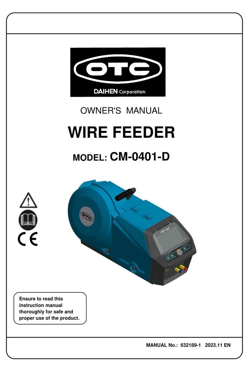
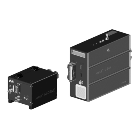
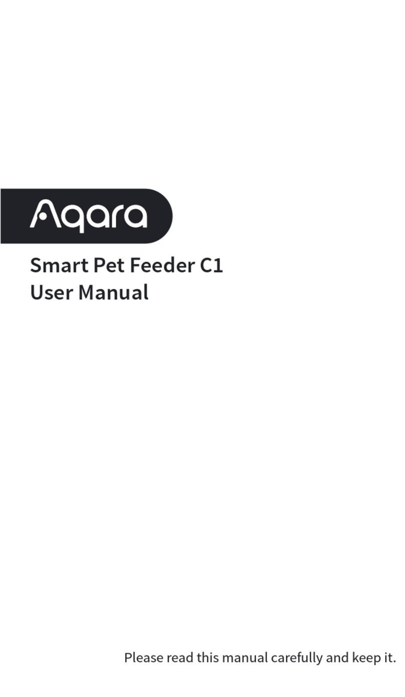
Daihen OTC CM-743-U User manual

OWNER'S MANUAL
WIRE FEEDER
MODEL: CM-743-U
Ensure
to
read
this
instruction
manual
thoroughly
for
safe and
proper
use
of
the
product.
DAIHEN Corporation
U30104
December 16, 2015
Manual No. : U30104-1

ll
Notice Machine export to Europe
This product does not meet the requirements specified in the
EC
Directives which are the
EU
safety
ordinance that was enforced starting on January
I,
1995. Please make sure that this product is not
alfowed to bring into the
EU
after January 1, 1995 as it is.
The same restriction is also applied
to
any country which has signed the EEA accord.
Please ask us before attempting to relocate or resell this product to
or
in any
EU
member country
or
any
other country which has signed the EEA accord.

TABLE OF CONTENTS
1.
SAFETY INFORMATION ................,.......................................... 1
2. ARC WELDING SAFETYPRECAUTIONS...............................2
3. CHECKING OF QUANTITY OF THE ACCESSORIES............. 9
4. NAMES OF PARTS.........................,...........
..
.............................9
5. CARRYING
AND
INSTALLING OF THE WIRE FEEDER...... 10
6. CONNECTION PROCEDURE.........,........................................ 12
7. WELDING PREP
ERA
TION..................................................... 17
8.
MAINTENANCE
AND
TROUBLESHOOTING........................26
9. PARTS LIST............................................................................32
10. SPECIFICATIONS...........................,........................................ 53

SAFETY INFORMATION
The following safety alert sy
mb
ols and signal words are used throughout this ma
nu
al to
i
de
ntify various hazards and special instruction
s.
~WARNING
~CAUTION
WARNING
gives
information
regarding
possible
personal
injury
or
loss
of
life.
CAUTION refers
to
minor
personal
injury
or
possible
equipment
damag
e.
Prohibited:
indicates
"
Prohibited
" matters.
- 1 -

fj ARC WELDING SAFETY PRECAUTIONS
~WARNING
ARC WELDING can be hazardous.
•PROTECT YOURSELF AND
OT
HERS FROM POSSIBLE SERIOUS INJURY
OR
DEATH.
Be sure to:
-Keep children away.
-Keep pacemakerwearers away until consulting a doctor.
• Read and understand the summarized safety information given below and the original principal
information that will befound in the PRINCIPAL SAFETY STANDARDS.
• Have only trained and experienced persons perform installation, operation, and maintenance
of
this equipment.
• Use only well maintained equipment. Repair or replace damaged parts
at
once.
ARC
WELDING is safe
when
precautions
are
taken.
l_lli
.,._
B_e_f_o_re_ u_s_in_g_ th_is_p_r_o_d_u_c_t_,_b_e_s_u_r_e_t_o_r_e_a_d_t_h_i_s_m_a_n
_u_
a_I
_.
_
____,
The device is manufactured using state-of-the-arttechnology and according
to recognised safetystandards.
If
used incorrectly
or
misused, however,
it
can
cause.
-injury
or
death
to
the operatorora third party,
-damage tothe device and other material assets
-belonging to the operating company,
-inefficient operation
of
the device
All persons involved in commissioning, operating, maintaining and servicing
the device must:
-be suitablyqu
al
ified
-have sufficient knowledge
of
welding
-read and follow these operating instructions carefully.
The operating instriuctions must always
be
at
hand wherever the device is
being used. In addition
to
the operating instructions, attention must all
so
be
paid
to
any general
ly
applicable and local regulations regarding accident
prevention and environmental protection
All safety and
danger
notices
on
the device
-must kept in a legible stake
-must not be damaged or marked
-must not be removed
-must not be covered, pasted
or
painted thecovers
-2 -

ARC WELDING SAFETY PRECAUTIONS (Continued)
~WARNING
1~
ELECTRIC SHOCK can kill.
Touching
live
electrica
l
parts
can
cause
fatal
shocks
or
severe
burns.
The
electrode
and
work
circuits
are
el
ectrica
lly
live
whenever
the
output
is
on.
The
power
line
and
internal
circuits
of
th
is
equ
i
pment
are
also
live
when
the
li
ne
disconnect
switch
is
on.
When
arc
we
l
ding
all
metal
components
in
the
torch
and
work
circuits
are
electrica
lly live.
•
Do
nottouch live electrical parts.
• Weardryinsulating gloves and other body protection thatare free
of
holes.
• Insulate yourselffrom work and ground using dry insulating mats
or
covers.
•
Be
sureto disconnectthe line disconnect switch before installing, changing torch
parts or maintaining this equipment.
• Properly install and ground this equipment according
to
its Owner's Manual and
national, state, and local codes.
• Keep all panels and covers
of
this equipmentsecurely
in
place.
•
Do
not use worn, damaged, undersized,
or
poorly spliced cables.
•
Do
nottouch electrode and any metal object if POWER switch is ON.
•
Do
notwrap cables around your body.
• When the wire feeder is not in use orthe work is interrupted for a long time, shut
off
the power
of
all units.
• Bl
ow
dry
air
to parts periodically to remove dust and dirt.
~f)
ARC RAYS can burn eyes and skin: FLYING SPARKS AND
HOT METAL can cause injury. NOISE can damage hearing.
Arc
rays
from
the
welding
process
produce
i
ntense
heat
and
strong
ultraviolet
rays
that
can
burn
eyes
and
skin
.
Noise
from
some
arc
we
l
ding
ca
n
damage
h
earing.
• Wearface shield with a propershade
of
filter (SeeANSI Z 49.1 listed
in
PRINCIPAL
SAFETY STANDARDS) to protect your face and eyes when welding or watching a
we
lderwork.
• Wearapproved safety goggles. Side shields recommended.
• Use protective screens or barriers to protect others from flash and glare: warn
others notto look at the arc.
• Wear protective clothing made from durable, flame-resistant material (wool and
leather)and foot protection.
• Useapproved earplugs
or
earmuffs
if
noise level is high. Chipping and grinding can
cause flying metal. As welds cool, they can throw
off
slag.
• Wearapproved face shield or safety goggles. Side shields recommended.
• Wear proper body protection to protect skin.
-3-

ARC WELDING SAFETY PRECAUTIONS (Continued)
~WARNING
-
~
~~
WELDING can cause fire and explosion.
"'9t'
Sparks and spatterfly
off
from the welding arc. The flying sparks and hot
metal, spatter, hot base metal, and hot equipment can cause fire and
explosion.
Accidental contact
of
electrode
or
welding wire to metal object can cause
sparks, overheating,
or
fire.
• Protectyourself and others from flying sparks and
hot
metals.
•
Do
notweld where flying sparks can strike flammable material.
• Remove all flammables within 33ft. [ 1
Om
]
of
the welding arc. If this is not possible,
coverthem with approved covers.
•
Be
alert thatwelding sparks and hot metals from welding can easily pass through
cracksand openings into adjacent areas.
• Watch forfire, and keep a fire extinguisher nearby.
•
Be
aware that welding on a ceiling, floor, bulkhead,
or
partition can ignite a hidden
fire.
•
Do
notweld on closed containers such as tanks
or
drums.
• Connect base metal side cable as close to the welding area as possible to prevent
the
we
lding currentfrom traveling along unknown paths and causing electric shock
and fire hazards.
• Remove stickelectrode from holder orcut
off
welding wire
at
contacttip when not in
use.
• Does not use the
we
lding power source
for
otherthan arc welding.
•
Wear
oil-free protective garments such as leathergloves, a heavyshirt, cuffless
tr
ousers, boots, and a cap.
• A loose cable connection can cause sparks and excessive heating.
• Tighten all cable connections.
• When there is an el
ec
trical connection between a work piece and the frame
of
wire
feeder
or
the wire reel stand,
are
may be generated and cause damage
by
a fire
if
thewire contacts the frame
or
thework piece.
-4-

ARC WELDING SAFETY PRECAUTIONS (Continued)
~WARNING
-
1-
F_U_M_E_S_ A_N_D_ G_A_S_E_S_ c_a_n_b_e_h_a_z_a_r_d_o_u_s_to_ y_o_u_r_h_e_a_lt
_h_.
-~
~
Arc
welding produce fumes and gases. Breathing these fumes and gasescan
be hazardous to
your
health.
• Keepyour head
out
of
the fumes. Do not breathethe fumes.
• Ventilate the area and/or use exhaust
at
the
arc
to
remove welding fumes and
gases.
•
If
ventilation is poor, use an approved air-supplied respirator.
• Read the Material Safety Data Sheets (MSDS) and the manufacturer's instructions
on metals, consumables, coatings, and cleaners.
•
Do
notweld or cut in locations neardegreasing, cleaning, orspraying operations.
The
heatand arc rays can reactwith vapors to form highlytoxicand irritating gases.
•
Work
in a confined spaceonly ifitis well ventilated,
or
while wearing an air-supplied
respirator. Shielding gases used for welding can displace
air
causing injury
or
death. Besurethe breathing airis safe.
CY
LINDER can explode
if
damaged.
A shielding gas cylinder contains high-pressure gas. If damaged, a cylinder
can explode.
Since gas cylinders are normally part
of
the welding process, be sure to treat
them carefully.
• Useonly correct shielding gas cylinders, gas regulator, hoses, and fittings designed
for
the specific application; maintain them in good condition.
•
Pr
otectcompressed gas cylinders from excessive heat, mechanical shock, and
arcs.
• Keepthe cylinder uprightand securely chained to a stationary support
or
a rack to
prevent falling ortipping.
• Keep cylinders awayfrom any welding orotherelectrical circuit.
• Nevertouch cylinder with welding electrode.
• Read and follow instructions on compressed gas cylinders, associated equipment,
and the CGA publication P-1 listed in PRINCIPAL SAFETY STANDARDS.
•Turn face awayfrom valve outletwhen opening cylinder valve.
• Keep protective cap in place
over
valve exceptwhen gas cylinder is in
use
or
connected foruse.
•
Do
notdisassemble or repairthe gas regulator exceptfor the person authorized by
the manufacturer
of
them.
- 5 -
ARC WELDING SAFETY PRECAUTIONS (Continued)
~WARNING
Be sure to observe the followings for preventing physical injuries,
a fire and electric shock.
Handling
of
plastic parts
Side
door
is
made
of
polycarbonate.
Make
sure
to
observe
the
following
notice.
•
Do
not apply external force and a shock to side door. Otherwise it maybe broken and in trouble.
• Polycarbonate parts can be weakened ordamaged
by
solvents and oils.
If
theside
door
or
covers are damaged, repair or replace immediately.
Do not alter
or
remodel our products.
•You mayget inijured
or
have your equipmentdamaged because
of
fire, failure
or
malfunction
caused byaltering or remodeling the product.
• The warranty does notcover
any
altered
or
remodeled products.
-6-

ARC WELDING SAFETY PRECAUTIONS (Continued)
~WARNING
~
Rotating parts
may
cause injuries. Be sure to observe the
following.
If
hands,
fingers,
hair
or
clothes
are
put
near
the
fan's
rotating
parts
or
wire
~
feeder's
feed
roll,
injuries
may
occur.
•
Do
not use this equipment ifthe case and the cover are removed.
• When the case
is
removed for maintenance/inspection and repair, certified
or
experienced operators must perform the work. Erect a fence, etc. around this
equipment to keep others awayfrom it.
• Before touching rotating parts for maintenance, inspection and repair, shut
off
the
welding power.
•
Do
not put hands, fingers, hair
or
clothes nearthe rotating fans
or
wire feed roll.
ARC WELDING work areas are potentially hazardous.
--
~
FALLING
or
MOVING
machine
ca
n
cause
serious
in
jury
.
• When hanging
the
welding power source by a crane, do notuse the carrying
handle.
• Placethe welding power source and wire feeder securely
on
a flat surface.
•
Do
not pull the welding power source across obstacles.
•
Do
not put wire feeder on the welding powersource.
•
Do
not put the welding power source and wire feeder where theywill pit
or
fall.
WELDING
W
IRE
can
cause
puncture
wou
nd
s.
•
Do
not press gun trigger until instructed to do so.
•
Do
not point guntoward any part
of
the body, other people,
or
any metal when
threading welding wire.
-7-

ARC WELDING SAFETY PRECAUTIONS (Continued)
PRINCIPAL SAFETY STANDARDS
Arc
welding
equipment-
Installation and use. Technical Specification
IEC
62081, from International Electro technical Commission
Arc
welding equipment Part 1: Welding powersources IEC 60974-1, from International
Electro technical Commission
Safety in Welding and Cutting, ANSI Standard Z49.1, from American Welding Society.
Safety and Health Standards,
OSHA
29
CFR
1910, from Superintendent
of
Documents,
U.S. Government Printing Office.
Recommended Practices
for
Plasma Arc Cutting, American Welding Society Standard
AWS
C5.2, from American Welding Society.
Recommended
Safe
Practices forthe Preparation
for
Welding
and
Cutting
of
Containers
Tha
t Have Held Hazardous Substances, American Welding Society Standard
AWS
F4.1,
from American Welding Society.
National Electrical Code,
NFPA
Standard 70, from National Fire Protection Association.
Safe Handling
of
Compressed Gases in Cylinders,
CGA
Pamphlet
P-1
, from
Compressed
Gas
Association.
Code for Safety
in
Welding and Cutting,
CSA
Standard W117.2, from Canadian
Standards Association, Standards Sales.
Safe
Practices
For
Occupation And Educational Eye And Face Protection, ANSI
Standard Z87.1, from American National Standards Institute.
Cutting And Welding Processes, NFPAStandard
51
B, from National Fire Protection
Association.
NOTE: The codes listed above may be improved
or
eliminated. Always refer
to
the
updated codes.
M050114
-8-

b
CHECKING
OF
QUANTITY
OF
THE
ACCESSORIES
Check the quantity
of
parts when opening the package.
Wire feeder Accessory
Description
CD
GAS
HOSE
(3m)
@
SW
I
TCH
CORD
@TERMINAL
@)V
IN
YL
CAP
@HOSE
COVER
HEXAGON
SOCKET
@
SCREW
KEY
(M4)
II
NAMES OF PARTS
•
Refer
to
the secti
on
indicated in D
for
details.
Specification
U597
1
ROO
U597
1
SOO
100-0816
100-0817
U1997C03
Feed
motor
[!!]
Wire
reel
hub
~
1
7
--
2
-,
-7.-4-I Pressure roll holder
~
Q'
ty
2
2
2
Gas
supply inlet
~
Pressure handl
es
~
Torch
socket
16.4 I
Feed rolls
~
-9-

CARRYING
AND
INSTALLING
OF
THE
WIRE
FEEDER
5.1. Transportation
~WARNING
Observe the following
to
avoid damage
to
the wire feeder
or
physical injury when
carrying the equipment.
1~
•
Do
nottouch the charging parts inside
or
outsidethe wire feeder.
• Disconnectthe wire feeder from the welding power source byturning
off
the line
disconnect switch in the power boxto avoid an electric shock before carrying the
equipment.
--
•
Be
sure to detach the wire reel from the wire feeder before lifting the equipment to
~
the high places by a crane.
5.2. Installation
~WARNING
When installing the wire fe
eder
, follow the instructions belowto avoid occurrence
of
fires during welding and physical damage
by
fume gas.
It
•
Do
not place the welding machine nearcombustible materials and flammable gas.
• Remove combustible materials to prevent dross coming into contact with
combustible object
s.
If
that not possible, coverthem with noncombustible covers.
~
•
To
avoid gas poisoning and danger
of
suffocation, weara gas mask
or
adequately
ventilate when using the welding machine in the place regulated bya local law.
•
To
prevent disorder
or
poisoning caused
by
fume, weara
gas
mask
or
weld
at
a
partial exhaust facility approved
by
the local regulation.
• Adequately ventilate
or
weara gasmaskwhen using the welding machine in atank,
a boiler, a hold
of
a ship, because heavier gas such as carbon dioxide
or
argon
gases are
dr
ifting there.
• When using the welding machine
at
a narrow space, complywith a trained
supervisor's directions. And be sure to
wear
a
gas
mask.
•
Do
notoperate the welding machine near
the
place where degreasing, cleansing,
and spraying are performed. Otherwise, poisonous gas
may
be generate
d.
•
Be
sure to
wear
a gas mask or adequately ventilate when welding a coating steel
plate. (Poisonous
gas
and fume may be generated.)
•
Do
not place the
we
lding powersource, wire feeder, torch, and control cable
(including the extensi
on
cable) in an area where the equipmentcan become wet.
-10
-

CARRYING
AND
INSTALLING
OF
THE
WIRE
FEEDER
(Continued)
~CAUTION
Followthe instructions below when selecting an installation place forthe wire
feeder.
• Do not install in areas exposed to direct sunlight and rain.
• Do notplace the welding powersource, wire feeder, torch, and contrailcable (includi
ng
the
extension cable) in an area wherethe equipment can becomewet.
• Install the wire feeder in the place where
is
altitude below 1,000m and the
amb
i
ent
temperature
is between -10°C and +40°C (
+1
4 °F and +104 °F).
• Install a wind
sh
ield to protect
arc
from wind.
• Fix the gas cylinderto a stand specifically made for gas cylinders.
-
11
-

iijCONNECTION PROCEDURE
ihCAUTION
Follow the Instructions below to avoid electric shock.
Do not touch live electrical parts, as this may cause in fatal shock and
severe burns.
Do not touch live electrical parts, as this
may
cause in fatal shock and severe
burns.
•
Do
nottouch live electrical parts
of
thewelding machine.
• H
ave
a qualified electric engineer ground thecase
of
the welding power source and
the base metal or
jig
electrically connected, following a local law.
• Disconnectthe wire feeder from the welding power source byturning
off
the line
disconnectswitch in the power boxto avoid an electric shock before grounding the
welding power source or base metal and connecting the cables
or
hoses.
•
Do
not use a cable with lack
of
capacity
or
a damaged cable.
• Tighten and insulate the connections
of
cables.
• Firmlyattach the cover
of
the welding machine afterconnection
of
the cables.
•
Do
not place the welding power source, wire feeder, torch, and control cable
(including the extension cable) in an area where the equipment can become wet.
• Insulate connected part
of
the bolt and the nutwith the insulating tape surelyafterit
tightens enough.
-12
-

If.I
CONNECTION PROCEDURE (Continued)
6.1. Connection flow chart
Firml
y atta
ch
the
conn
e
ct
ors
by
turning
th
e c
onn
ec
tor
s
in
the
c
lo
ckwis
e di
recti
on.
Gas regulator
Gascylinder
Control cabl
e*
@
Wire feeder
Control cable for remote control
Analog remote control (Option) Base metal
Powercable for base metal* @ Ground a work piece
=
if
a local law requires.
CD
NOTE:
• Standard composition consists
of
the parts indicated in D .
Preparation
of
the parts except the standard composition is required to
use
the wire feeder.
• F
or
cables and hoses marked
with"*",
dedicated cables and hoses having differentlength are
provided. Fordetails, refer to information in "9.14. Optional Accessory".
I
CD
Ground the base metal.
Connect
the
powercable for base
® metal betweenthe negative output
terminal and the base metal.
Connect
the
gas hose tothe gas
@ supply inleton the back s.ide
of
the
wire feeder.
Connect the powercable forthe wire
IA'\
feeder into the positive output
~ terminal
on
the welding power
source.
-13
-
Afterremoving the right-side plate
of
the wire feeder, connectthe power
® cable forthe wire feeder
to
thecopper
bar
on
the torch adaptor.
Connect the control cable forthe wire
@feeder (10P) i
nto
the wirefeeder
socket
on
the
w
eld
i
ng
power
source
.
(f) Connect the welding torch to the wire
feeder.
[[!]

If.I
CONNECTION PROCEDURE(Continued)
6.2. Connecting
of
the Gas Hose
~WARNING
• You may suffer
fr
om danger
of
suffocation caused bylack
of
oxygen when shield
gas
keeps drifting
in
a closed place. Besure to turn off
the
shield gas
at
the main
when the
we
lding powersource is not in use.
• Besure
to
connectthe gas hoseafter fixing to thestand, as physical inj
ur
ies mayresultfrom the
gas cylinder falling down.
• Attach a propergas regulator
to
thegas cylinder. Failure
to
observe thisrequirement
may
result
in physical injuries. The gas regulatorfor high pressure gas must be used.
•How
to
connect
the
gas
ho
,
se
Connect the gas hosefollowing the procedure shown below.
" Gas regulator
Gas hose
Firmly
tighten
the
nuts
using
a
wr
ench,
et
c.
to
connect
the
gas
hose
and
gas
regulator
.
-14
-
of
C@.
Gas
hose~

If.I
CONNECTION PROCEDURE (Continued)
6.3. Connecting
of
the PowerCable
~WARNING
Touching
liveelectrical
parts
may
cause
in
fatal electric
shock
and severe
burns
.
•
Do
nottouch live electrical parts
of
the welding machine.
• Have a qualified electric engineer ground
the
case
of
the
welding powersource and
the
base
metal
or
jig electricallyconnected in accordance with a local law.
• Disconnect
the
wire feeder from the welding powersource
by
turning
off
the li
ne
di
sco
n
nect
sw
itch in the power box to avoid
an
electric shock before the welding powersource
or
base
metal and connecting the cables
or
hoses.
• Afterconnecting the cables, cover the powersource with the cover
or
case.
• When using
the
welding machine in such a humid environment
as
construction site, on the steel
plate,
or
on steel structure, install a leakage breaker.
~CAUTION
• Use the proper
power
cable that matches
the
welding current.
We
lding
curr
e
nt
Ca
ble
thickn
e
ss
0
200A
AWG
1 [38mm2)
or
more
200
350A
AWG
2/0 [60mm2
]or
mor
e
350
SOOA
AWG
3/0 [80mm2]
or
mor
e
*W
hen performing pulse welding using a 56ft. [17m]
or
morecable, usethe thickercable
by
one rank.
•
How
to
connect
the
pow
er cable
Connectthe power cable following the procedure shown below.
• When installi
ng
the sideframe,
insertthe overlapping
part, first.
-15
-
Stopper Nut
P
ower
cable
for
wire feeder
Recommended
tightening
t
orqu
e
M10: 24 N•m

If.I
CONNECTION PROCEDURE(Continued)
6.4. Connecting
of
the Welding Torch
We
ld
in
g torch is
co
nnected with the part torch adaptorof Wire feeder,
fi
xing bolt is t
ig
htened,
and welding torch is fixed.
~CAUTION
• Please tighten fixing bolt securelyto fix Torch. Otheiwise,
it
causes
the
electric shockand a fire
by
feeding pow
er
the defect.
., Wire feeder Torch adaptor
Welding torch
''WT
••
••
-S(M)(L)UT" series
Fitting bolt
[Note]
This product can connect the following welding torch
per
the
standard
spec
ifications.
-OTC
C0
2
/MAG
Welding torch
"WT3510- S(M)(L)U
T'
ser
ies
.,
"WT
4000-S(M)(L
)UT'
series
When
following
welding
torch
is
conn
ec
ted,
it
is
necessa
ry
to
prepare
optional
parts
a
nd
o
ptional
kit
separately.
•
OTC
C0
2/MAG Weldi
ng
torch
"WT5000-S(M)(L)UT' series
Option kit:
To
r
ch
adaptor k
it
(K
5975
K
OO)
•
OTC
MIG Welding torch
"WTA200-SUT", "WTA300-SU
T"
,"WTAW400-SU
T'
"1
Option kit: Aluminum kit (K5975E
OO)
*1: When using this torch, the
Water
Cooling kit (K5975LOO) is required.
Please use
the
fol
lowing
torches
if
volt
age de
tection
is re
quir
ed.
•
OTC
C0
2/MAG Welding torch
"WT3500-S(M)(L)D" series
"WT3510-S(M)(L)D" series
"WT3520-S(M)(L)D" series
Option kit: Voltage detection adaptor kit (K
5975VOO)
-16
-

d WELDING PREPERATION
7.1. Checking
of
wire size I Replacement
of
feed roll
Check wheth
er
t
he
feed ro
ll
s suitable to the wire being used are installed.
r
\..
Use feed rolls suited to the wire siz
e.
Using an improperfeed roll will cause it slip to disable normal wire feed
or
deform the wire,
resulting in improperwelding.
• Procedure
for
checking feed roll
Checkwhetherfeed rolls suitable
for
the wire sizeare mounted following
the
procedure
show
n below.
-17
-
Table of contents
Other Daihen Wire Feeder manuals