manuals.online logo
Brands
  1. Home
  2. •
  3. Brands
  4. •
  5. Daikin
  6. •
  7. Refrigerator
  8. •
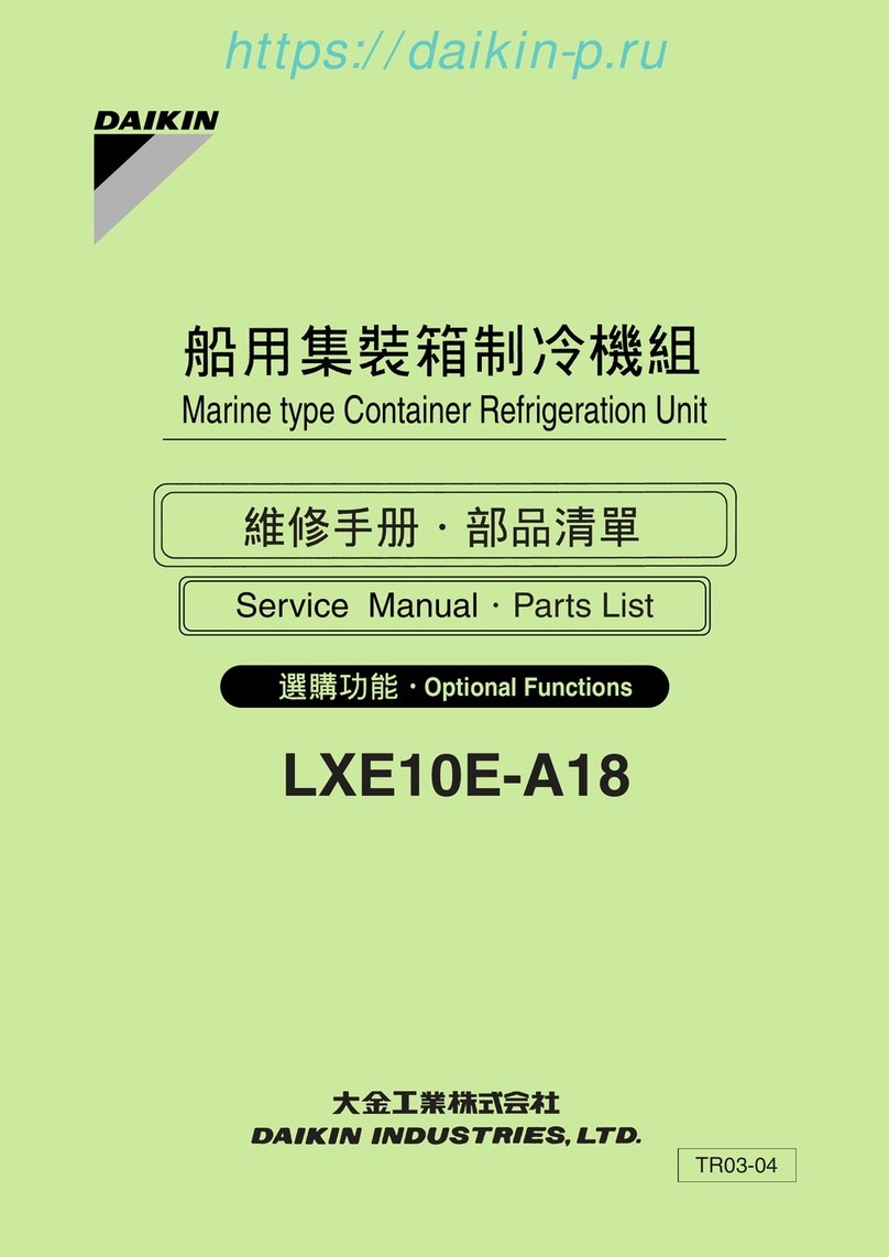
  9. Daikin LXE10E Series User manual

Daikin LXE10E Series User manual

TR08-03B
(2010.3.31.00150)NK
$5,00
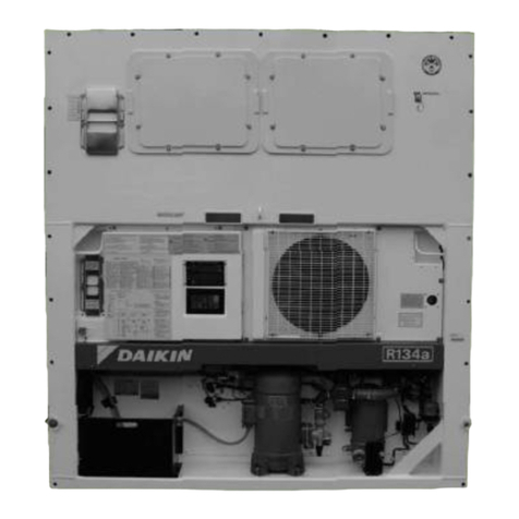
Marine type Container Refrigeration Unit Service Manual LXE10E100 or later
DAIKIN CONTAINER
LXE10E-A
TR 08-03B
Marine type
Container Refrigeration Unit
Service Manual
Head Office. Umeda Center Bldg., 4-12, Nakazaki-Nishi 2-chome, Kita-ku, Osaka, 530-8323 Japan.
Tel: 06-6373-4338
Fax: 06-6373-7297
Tokyo Office. JR Shinagawa East Bldg., 11F 18-1, Konan 2-chome, Minato-ku Tokyo, 108-0075 Japan.
Tel: 03-6716-0420
Fax: 03-6716-0230
LXE10E100 or later
(DECOSⅢe)
https://daikin-p.ru
1
Please read the contents of this manual prior to operation of the unit.
This booklet will provide you with the minimum necessary information
required to operate the Daikin refrigerated unit LXE10E100 or later
equipped with the new controller DECOSⅢe. It covers all of the unit's
functions from basics such as the names of components, how to turn on
the power supply, or change a setting temperature, to describing functions
of product and maintenance service.
In addition, refer to the manuals listed below will be issued soon.
●Parts List
●Operation Manual of Personal Computer Software
The English text is the original instruction. Other languages are translations
of the original instructions.
https://daikin-p.ru
CONTENTS
3.4 Back up Battery...........................................3-29
3.4.1 Specifications .......................................3-29
3.4.2 Function................................................3-29
3.4.3
Checking the remaining battery voltage
..3-29
3.4.4 Battery replacement
(Rechargeable battery)
............................
3-30
3.5
Information interchange with personal computer
...3-34
3.5.1 Data logging .........................................3-34
3.6
Controller replacement and software upgrade
...3-35
3.6.1 Controller replacement .........................3-35
3.6.2 Installation of software of latest version
(version upgrade) .................................3-39
3.7 Pre-Trip Inspection......................................3-40
3.7.1 Manual inspection ................................3-41
3.7.2 Automatic PTI.......................................3-43
3.7.2.1 Automatic PTI selection mode.......3-43
3.7.2.2 Short PTI (S.PTI)...........................3-44
3.7.2.3 Alarm list during PTI
(Pre-Trip Inspection)......................3-45
3.7.2.4 Manual check (M.CHECK) ............3-46
3.8 Chartless function .......................................3-48
3.8.1 Chart indication function.......................3-48
3.8.2 P code (Pull down time indication) .......3-50
3.8.3 Chartless code display function............3-51
3.8.3.1 List of chartless code.....................3-51
3.8.3.2 H-code...........................................3-52
3.8.3.3 d-code ...........................................3-54
3.9 Communication modem ..............................3-55
4. SERVICE AND MAINTENANCE........................4-1
4.1 Maintenance service .....................................4-1
4.1.1 Collection of refrigerant ..........................4-1
4.1.2 Gauge manifold ......................................4-1
4.1.3 Automatic pump down............................4-3
4.1.4 Refrigerant recovery and charge............4-5
4.2 Main components and maintenance .............4-8
4.2.1 Scroll compressor...................................4-8
4.2.2 Fan and fan motor ................................4-14
4.2.3 PT and CT board (EC9756) .................4-15
4.2.4 Electronic expansion valve...................4-17
4.2.5 Suction modulation valve .....................4-18
4.2.6 Drier......................................................4-19
4.2.7 Solenoid valve ......................................4-20
4.2.8 Discharge pressure regulating valve ....4-21
4.2.9 Check valve..........................................4-21
4.2.10 High-pressure switch (HPS) ...............4-22
4.2.11 Low pressure transducer (LPT)..........4-22
4.2.12 High pressure transducer (HPT) ........4-23
4.2.13
Air-cooled condenser and evaporator
...4-23
4.2.14 Fusible plug ........................................4-23
4.2.15 Liquid/moisture indicator ....................4-24
4.2.16 Evacuation and dehydrating...............4-25
4.3 Periodic Inspection Items ............................4-27
SAFETY PRECAUTIONS
• Danger .................................................................4
• Warning................................................................5
• Caution.................................................................6
1. INTRODUCTION.................................................1-1
1.1 Operation range ............................................1-1
1.2 Basic names of components .........................1-1
1.3 Basic operation of refrigeration unit ..............1-2
1.3.1 Starting operation ...................................1-2
1.3.2 Check items during operation.................1-3
1.3.3 Procedure after operation.......................1-3
1.3.4 Adjust the ventilation ..............................1-4
2. GENERAL DESCRIPTION.................................2-1
2.1 Main specifications........................................2-1
2.2 Names of components ..................................2-2
2.2.1 Outside ...................................................2-2
2.2.2 Inside......................................................2-5
2.2.3 Control box .............................................2-7
2.3 Set point of protection devices
....................
2-10
2.4 Operating pressure and running current .....2-11
2.5 Operation modes and control......................2-15
2.5.1 Frozen operation ..................................2-15
2.5.2 Chilled operation ..................................2-17
2.5.3 Defrosting operation .............................2-19
2.5.4 Dehumidification control operation
(Optional)..............................................2-22
2.5.5 Common control ...................................2-23
3. ELECTRONIC CONTROLLER...........................3-1
3.1 Basic operation of electronic controller .........3-1
3.1.1 Control panel ..........................................3-1
3.2 Operation procedure .....................................3-4
3.2.1 Operation procedure flow chart ..............3-4
3.2.2 Mode operation procedure .....................3-7
1.
Current (Operation state) indication mode
...3-7
2. Operation setting mode ..........................3-8
3. Battery mode ..........................................3-9
4. Mode operation ....................................3-10
5. LED display light-OFF mode ................3-11
6. Sensor indication mode........................3-12
7. Temperature record scroll mode ..........3-15
8. Alarm record scroll mode .....................3-17
9. PTI record scroll mode .........................3-18
10. Optional function setting mode...........3-19
11. Basic function setting mode ...............3-20
12. Optional condition setting mode .........3-22
13. Input data mode .................................3-24
14. Controller software download mode...3-25
3.3 Alarm display and back-up function ............3-26
3.3.1 Alarm list...............................................3-26
3.3.2 Back-up operation at the time of control
sensor abnormality ...............................3-27
3.3.3 Backup operation at the time of sensor
abnormality...........................................3-27
https://daikin-p.ru
CONTENTS
6.5.3 Emergency operation of electronic
expansion valve....................................6-23
6.5.4 Emergency operation of suction
modulation valve ..................................6-24
7. APPENDIX..........................................................7-1
7.1 Standard tightening torques for bolts ............7-1
7.2 Standard tightening torque for flare nut.........7-1
7.3
Resistance of motor coil and solenoid valve coil
...7-1
7.4
Temperature conversion table and temperature
sensor (SS/RS/DSS/DRS/RSS/RRS/EIS/EOS/
SGS/AMBS) characteristics table
....................7-2
7.5 T
emperature conversion table and temperature
sensor (DCHS) characteristics table
..................7-3
7.6
High and low pressure sensor characteristics table
..7-4
7.7 HFC134a, temperature-vapor pressure
characteristics table ......................................7-5
7.8 Electric wiring pilot lamps and monitoring
circuit (option)................................................7-6
7.9 Fuse protection table.....................................7-7
7.10 Schematic wiring diagram (LXE10E136) ....7-8
7.11
Stereoscopic wiring diagram (LXE10E136)
.....7-9
5. OPTIONAL DEVICES.........................................5-1
5.1 Electronic temperature recorder....................5-1
5.1.1 Standard type .........................................5-1
5.1.2 Rechargeable battery type .....................5-3
5.2 Cold treatment transport ...............................5-4
5.2.1 Setting the number of USDA sensor
connetions ..............................................5-4
5.2.2 USDA sensor calibration ........................5-4
5.2.3 USDA report ...........................................5-4
5.2.4 Battery check and replacement..............5-4
5.2.5 USDA sensor types and setting .............5-5
5.3 TransFRESH.................................................5-6
5.4
Ventilator outlet opening detection (FA sensor)
...5-8
5.5
Daikin Temperature Management System (optional)
..5-11
5.6
Automatic Setpoint Change: ASC (optional)
..5-13
5.7
Automatic Cold Treatment: ACT (Optional)
....5-15
6. TROUBLESHOOTING........................................6-1
6.1 Refrigeration system and electrical system...6-1
6.2 Alarm codes on electronic controller ...........6-13
6.3
Troubleshooting for automatic PTI (J-code)
...6-16
6.4 Diagnosis based on the recording chart......6-18
6.5 Emergency operation ..................................6-21
6.5.1 Emergency operation of controller .......6-21
6.5.2 Short circuit operation of controller.......6-22
https://daikin-p.ru
Always shut off the main power supply of the facility
before disconnecting the power plug.
4
SAFETY PRECAUTIONS
DANGER
Always turn off the main power supply of the facility
before inspecting the interior of the control box.
※
This is important because high voltage remains at the
circuit breaker and the optionally provided modem even
though the circuit breaker in the control box is turned off.
Always observe the following points before operating or
inspecting a unit.
High voltage
Circuit breaker
Modem (optional)
https://daikin-p.ru
Do not touch the condenser fan while power to the
unit is ON.
Before removing the condenser fan cover, turn off the
circuit breaker and disconnect the power plug.
During air-cooled operation : Condenser fan may start
and stop automatically for
the refrigerant high
pressure control.
During water-cooled operation: Condenser fan may start
and stop automatically for
cooling of the control box.
5
WARNING
https://daikin-p.ru
6
CAUTION
Before starting the unit, run the generator.
Securely close the control box cover.
Otherwise, it will allow water entry.
Temperature recorder box cover
Temperature Recorder (OPTION)
Control box cover
Quick-lock lever
https://daikin-p.ru
7
CAUTION
Wash the refrigeration unit with fresh water at PTI.
1. Carefully flush the external condenser with fresh water to remove the
salt that sticks to it.
2. Corrosive gases generated from the cargo may corrode the copper
pipes and aluminium fin of the internal evaporator. Therefore, wrap up
the cargo properly to prevent such corrosion.
Major corrosive gases include chlorine, ammonia, sulfuric acid, acetic
acid, sulfur dioxide etc.
https://daikin-p.ru
8
Use only exclusive tools for HFC134a. (gauge manifold, etc)
Do not use any tools for CFC12 or HCFC22.
Service ports with exclusive quick joints for HFC134a are provided in the refrigeration
unit to avoid improper refrigerant or refrigerant oil from entering into the refrigeration
circuit. (Refer to clause 4.1.2)
The charging hose and gauge port are not interchangeable with those of previous
models using other refrigerants.
8
CAUTION
Refrigerant and refrigerant oil
Be sure to only charge the unit with refrigerant HFC 134a.
Never attempt to use any other refrigerant (CFC12, HCF22, etc) with the
refrigeration unit.
If any other refrigerant not specified is charged, it may cause problems with the unit.
Use only Daikin specified refrigerant oil (IDEMITSU, Daphne Hermetic Oil
FVC46D).
If any other refrigerating machine oil not specified is charged, it may cause problems
with the unit.
Open the oil can, just before charging the oil, and use all the oil in the can once
opened.
Do not leave the can open for 5 hours or longer to avoid moisture entry.
Using any refrigerant oil which has absorbed moisture may cause problems with the
unit.
Moisture Moisture
DAPHNE
HERMETIC OIL
FVC46D
SUNISO
3GS- DI
D
A
P
H
N
E
H
E
R
M
E
T
I
C
O
I
L
F
V
C
4
6
D
S
W
-
4
6
OIL
https://daikin-p.ru
9
CLASS 1 PRODUCT SPECIFIED BY THE LAW CONCERNING THE RECOVERY AND
DESTRUCTION OF FLUOROCARBONS OF FLUOROCARBONS
HFC IS USED FOR THIS PRODUCT AS A REFRIGERANT.
(1) EMISSION OF FLUOROCARBONS INTO THE ATOMOSPHERE WITHOUT
PERMISSION IS PROHIBITED.
(2) RECOVERY OF FLUOROCARBONS IS MANDATORY WHEN SCRAPPING AND
SERVICING THIS PRODUCT.
(3) THE KIND OF FLUOROCARBON AND ITS AMOUNT ARE STATED IN THE
MANUFACTURER'S LABEL OR THE ADDITIONALLY CHARGED AMOUNT LABEL.
This product contains greenhouse gases covered by Kyoto Protocol.
Do not discharge refrigirant into atmosphere.
Refrigerant type : R134a
GWP (1) value : 1300
(1) GWP=global warming potential
The refrigerant quantity is indicated on the unit name plate.
Important information regarding the refrigerant
https://daikin-p.ru
1-1
1. INTRODUCTION
1.1 Operation range
Use the units within the following range.
1.2 Basic names of components
External temperature range
Internal temperature range
Voltage
Vibration and shock
Operation range
-30˚C to +50˚C (-22˚F to + 122˚F)
-30˚C to +30˚C (-22˚F to + 86˚F)
50Hz: 380V/400V/415V, 60Hz: 440V/460V
Voltage fluctuation rate should be within ±10%
Horizontal: 5G, Vertical: 2G
Item
qCompressor
wAir-cooled condenser
eReceiver
rEvaporator
tControl box
Outside: switch, manual defrost switch, monitoring
receptacle
Inside: circuit breaker
yAir-cooled condenser fan
uDrier
iAccess panel
oStorage space for power cable
!0 Ventilator
!1 Thermometer check port (optional)
Use this port to measure the
inside return air temperature.
!2 Gas sampling port This is used to measure the
Sampling port (Supply) inside supply air temperature
and inside CO2concentration.
!3 Liquid moisture indicator
!4 Recorder (optional)
⎛
⎜
⎜
⎝
⎞
⎟
⎟
⎠⎛
⎜
⎜
⎝
⎞
⎟
⎟
⎠
⎛
⎝⎞
⎠
112
13
2
3
7
6
10
11
5
9
8
14
4
https://daikin-p.ru
1-2
1.3.1 Starting operation
(1) Connect the power plug to the power supply.
Insert the plug qsuited to the power source
voltage, and fasten the plug firmly.
(2) Turn on circuit breaker wafter checking that
the power supply switch is turned on
(Outside of the unit).
(3) Close the control box cover.
Ensure that the one-touch lever is firmly closed.
(4) Press the UNIT ON/OFF key e.
1.3 Basic operation of refrigeration unit
1
w
e
Control box cover
Quick-lock lever
https://daikin-p.ru
1-3
1.3.2 Check items during operation
1. Check the compressor, fan, pipes, etc. for abnormal
noise and vibration.
2.
Check the refrigerant for shortage.
Check for excessive charge.
3. Check the refrigerant for moisture inclusion.
[When the moisture indicator is exposed to gas
refrigerant during prolonged stop periods, it may turn
yellow. This is not abnormal.]
4. Check if the recorder is working according to the inside
temperature.
Method of check
Visual and sound check
Visual check by using the moisture indicator
For the details, refer to clause 4.2.15.
Visual
The moisture indicator colour;
Green: normal
Yellow: abnormal.
Visual
5. Check operating conditions using the control panel.
Visual
Check items(precautions)
q
e
w
1.3.3 Procedure after operation
(1) Turn off the UNIT ON/OFF key e, and turn off
the circuit breaker w.
(2) Close the control box cover.
Ensure that the one-touch lever is firmly closed.
(3) Stow the power cable.
Disconnect the power plug q, and stow the
power cable directing the plug opening
downward to prevent sea water or rain water
from collecting in the power plug.
Liquid moisture indicator
https://daikin-p.ru
CAUTION
Keep the ventilation closed when
ventilation is not necessary or during
transportation of the frozen cargo.
1.3.4 Adjust the ventilation
Adjust the opening of the ventilation
according to the cargo.
"CLOSE" "OPEN"
Air inlet Ventilation cover
Handle
Air outlet
Air inlet
Air outlet
Nameplate
Arrow mark
Set the arrow mark of the handle to "CLOSE"
when ventilation is not required or during
frozen operation.
When ventilation is required (chilled mode)
slide the handle upward.
*
Set the arrow mark of the ventilation at the
scale on the nameplate according to the
required ventilation amount.
1-4
◆Fresh air suction amount
The scale marks on the nameplate are the
reference ones, not guaranteeing the amount.
Fresh air suction amount (ventilation amount)
varies in accordance with static pressure
differences, the container conditions, cargo
loading condition in the container, and power
supply (voltage, frequency).
・In the case of the same static pressure,
fresh air suction amount at 50 Hz is reduced
to approximately 5/6 of that at 60 Hz.
Nameplate attached to the unit
https://daikin-p.ru
2-1
2. GENERAL DESCRIPTION
2.1 Main specifications
Model
Item LXE10E100 or later
Condenser cooling system Air cooled type
Controller DECOS3e
Power supply AC 3-phase 380V/400V/415V 50Hz, 440V/460V 60Hz
Compressor Full hermetic scroll type (Motor output: 5.5kW)
Evaporator Cross fin coil type
Air-cooled condenser Cross fin coil type
Evaporator fan Propeller fan
Evaporator fan motor Three-phase squirrel-cage induction motor
Condenser fan Propeller fan
Condenser fan motor Three-phase squirrel-cage induction motor
Defrosting
Hot-gas defrosting system
Dual timer, on-demand defrost and manual switch
Detecting the temperature of evaporator outlet pipe and return air
Electronic expansion valve
Capacity control
Capacity control with hot gas bypass and suction modulating valve
Protective devices
/Safety devices
Circuit breaker, PT/CT board (for over current protection).
Condenser fan-motor thermal protector
Evaporator fan-motor thermal protector
High-pressure switch, Fusible plug, Fuse (Glass tube fuse)
Refrigerant charged amount R134a : 5.2 (kg)
Refrigerant oil charged amount IDEMITSU, Daphne hermetic oil FVC 46D : 3.4(R)
Weight For details, refer to the specifications of each model. (459kg
in case of LXE10E136A1)
System
Initiation
Termination
Refrigerant flow control
Compressor thermal protector
https://daikin-p.ru
2-2
2.2 Names of components
2.2.1 Outside
●LXE10E
qAccess panel
wThermometer check port (Return air, optional)
※Thermometer check port is not fitted to some models.
eCondenser fan motor (CFM)
rTemperature recorder box (Option)
tHot-gas solenoid valve (HSV)
yDefrost solenoid valve (DSV)
uDischarge gas by-pass solenoid valve (BSV)
iElectronic expansion valve (EV)
oEconomizer solenoid valve (ESV)
!0 Injection solenoid valve (ISV)
!1 Air-cooled condenser
!2 Liquid/moisture indicator
!3 Liquid receiver
!4 Dryer
!5 Liquid solenoid valve (LSV)
!6 Suction modulating valve (SMV)
!7
Discharge pressure regulating valve (DPR)
!8 Compressor suction pipe temperature
sensor (SGS)
!9 Ambient temperature sensor (AMBS)
@0 Thermometer check port (Supply air)
@1 Compressor (CM)
@2 Discharge pipe temperature sensor
(DCHS)
@3 Storage space for power cable
@4 Low pressure transducer (LPT)
@5 High pressure transducer (HPT)
@6 High pressure switch (HPS)
@7 Control box
@8 Ventilator
22 21 20 1918
8
12
6
10
4
28
5
3
25
2
27
23
1
11
9
15
13
26
14
7
24
17 16
15
19
Refer to the next page
for detail of solenoid
valves
Refer to page 2-4 for
detail of compressor
and refrigerant control
devices
https://daikin-p.ru
2-3
●LXE10E
· Detail of solenoid valves
[Valve]
BSV :Discharge gas bypass Solenoid Valve
DSV :Defrost Solenoid Valve
DPR :Discharge Pressure Regulator Valve
EV :Electronic Expantion Valve
ESV :Economizer Solenoid Valve
HSV :Hot gas Solenoid Valve
ISV :Injection Solenoid Valve
RSV :Reheater Solenoid Valve (Optional)
for dehumidification control
LSV :
Liquid solenoid valve (Refer picture felow)
EV
ISVBSV
DSV ESVHSV
RSV
(option)
[Sensor]
AMBS: Ambient temperature sensor
DCHS: Discharge Gas Temperature Sensor
DPR : Discharge Pressure Regulator Valve
HPS : High Pressure Switch
HPT : High Pressure transducer
LPT : Low pressure transducer
SGS : Compressor suction pipe temperature sensor
[Valve]
SMV : Suction modulating valve
· Detail of compressor and refrigerant control devices
LPT
DCHS
HPT
HPS
Sensor
Valve
Service Port wq r t e
AMBS
SGS
DPR
SMV
LSV
Drier
Receiver
Liquid Moisture
Indicator
[Service port]
qLow pressure
wHigh pressure
eLiquid pressure
rHigh pressure
tLiquid pressure
For operation pressure check
Refrigerant recovery or vacuum
dry
For Refrigerant charging
(For details, refer to page 4-5.)
https://daikin-p.ru
2-4
Solenoidvalveandactivation
BSV :Discharge gas by-pass solenoid valve
BSV bypasses discharge gas to the suction side of the compressor to maintain low
pressure at low outside temperatures.
DSV :Defrost solenoid valve
DSV supplies discharge gas (hot gas) from the compressor to the evaporator to defrost.
E V :Electronic expansion valve
EV controls the evaporator outlet superheat by using the temperature sensor at the
evaporator outlet and inlet to control the refrigerant flow rate to the evaporator.
In case of EV coil abnormality or the controller malfunctions, the emergency magnet can be
used to manually set the opening.
HSV :Hot gas solenoid valve
HSV supplies hot gas to maintain the temperature inside during chilled operation at low
outside temperature.
ISV :Injection solenoid valve
ISV is activated when the following cases occur:
1)When compressor discharge gas temperature is too high (for the protection of the
compressor and lubricant)
2)
When refrigerant flow rate is too low during defrosting operation. The defrosting time can
be shortened with appropriate amount of refrigerant.
LSV :Liquid solenoid valve
LSV closes for pump down operation and during the automatic pumping-down and
defrosting operations.
RSV :Reheater solenoid valve (to control dehumidification)
RSV is activated during dehumidification operation to supply discharge gas (hot gas) from
the compressor to the reheater coil.
SMV :Suction modulating valve
SMV automatically adjusts its opening to control the refrigerant flow rate by using the
supply air temperature sensor SS during chilled operation.
The valve is fully open during pull-down or frozen operation. In case of SMV coil
abnormality or the controller malfunctions, the emergency magnet can be used to fix the
opening in full
https://daikin-p.ru
2-5
2.2.2 Inside
●LXE10E
qEvaporator fan motor (EFM)
wEvaporator
eSupply air temperature sensor (SS)
Data recorder supply air temperature sensor (DSS)
Temperature recorder supply air temperature sensor (RSS,
optional)
rEvaporator outlet pipe temperature sensor (EOS)
tEvaporator inlet pipe temperature sensor (EIS)
yReturn air temperature sensor (RS)
Data recorder return air temperature sensor (DRS)
Temperature recorder return air temperature sensor (RRS,
optional)
uUSDA receptacle [Optional]
Lateral and rear type depending on the
models
iPC port receptacle
7
8
6
2
3
1
5
4
USDA receptacle
PC port receptacle
https://daikin-p.ru
2-6
[Sensor]
DRS:Return Air Temperature Sensor for Datacorder
DSS:Supply Air Temperature Sensor for Datacorder
EIS :Evaporator Inlet Temperature Sensor
EOS:Evaporator Outlet Temperature Sensor
HuS :Humidity Sensor (Optional)
RS :Return Air Temperature Sensor
RRS:Return Air Temperature Sensor for Temperature Recorder (Optional)
SS :Supply Air Temperature Sensor
RSS:Supply Air Temperature Sensor for Temperature Recorder (Optional)
· Inside Detail
EIS
RS/DRS/RRS
EOS
HuS (optional)
※Reheater coil for
Dehumidification Control
(optional)
Evaporator Drain Pan Heater
https://daikin-p.ru

This manual suits for next models

1

Other Daikin Refrigerator manuals

Daikin Exigo E1500 User manual

Daikin

Daikin Exigo E1500 User manual

Daikin LXE10D-A15 Troubleshooting guide

Daikin

Daikin LXE10D-A15 Troubleshooting guide

Daikin LXE10E-A18 Troubleshooting guide

Daikin

Daikin LXE10E-A18 Troubleshooting guide

Daikin LXE10E-A17 Troubleshooting guide

Daikin

Daikin LXE10E-A17 Troubleshooting guide

Daikin LXE10E-A18A Troubleshooting guide

Daikin

Daikin LXE10E-A18A Troubleshooting guide

Daikin LXE10E-A17 User manual

Daikin

Daikin LXE10E-A17 User manual

Daikin LXE10E-A26B Troubleshooting guide

Daikin

Daikin LXE10E-A26B Troubleshooting guide

Daikin LXE10E-A27A Troubleshooting guide

Daikin

Daikin LXE10E-A27A Troubleshooting guide

Daikin LXE10D-A15A User manual

Daikin

Daikin LXE10D-A15A User manual

Daikin LXE10E-A33 Troubleshooting guide

Daikin

Daikin LXE10E-A33 Troubleshooting guide

Daikin LRLEQ5AY1(E) User manual

Daikin

Daikin LRLEQ5AY1(E) User manual

Daikin LXE10E100 User manual

Daikin

Daikin LXE10E100 User manual

Daikin LXE10E-A31 Troubleshooting guide

Daikin

Daikin LXE10E-A31 Troubleshooting guide

Daikin LX10F10A User manual

Daikin

Daikin LX10F10A User manual

Daikin LXE10E136GE User manual

Daikin

Daikin LXE10E136GE User manual

Daikin LFMNS0150AXV1 Specification sheet

Daikin

Daikin LFMNS0150AXV1 Specification sheet

Daikin LXE10E-A23 Troubleshooting guide

Daikin

Daikin LXE10E-A23 Troubleshooting guide

Daikin LXE10E-1 Troubleshooting guide

Daikin

Daikin LXE10E-1 Troubleshooting guide

Popular Refrigerator manuals by other brands

Videocon D 380 MF owner's manual

Videocon

Videocon D 380 MF owner's manual

Zanussi ZXAE15DW1 user manual

Zanussi

Zanussi ZXAE15DW1 user manual

GE Spacemaker GMR06AAZ Owner's Manual & Installation Instructions

GE

GE Spacemaker GMR06AAZ Owner's Manual & Installation Instructions

Frigidaire CGHT1846MP use & care

Frigidaire

Frigidaire CGHT1846MP use & care

VOX electronics FD458IXE operating instructions

VOX electronics

VOX electronics FD458IXE operating instructions

Fisher & Paykel RS2484WR installation guide

Fisher & Paykel

Fisher & Paykel RS2484WR installation guide

Ariston BD 2631 EU operating instructions

Ariston

Ariston BD 2631 EU operating instructions

Amana ABR2222FES Product dimensions

Amana

Amana ABR2222FES Product dimensions

McCall MCCF27 Service, installation and care manual

McCall

McCall MCCF27 Service, installation and care manual

Maytag MSD2573VEB Energy guide

Maytag

Maytag MSD2573VEB Energy guide

Beko TSE 1410 user manual

Beko

Beko TSE 1410 user manual

GE TB12S use & care

GE

GE TB12S use & care

ColdTech J3GR-69S Specifications

ColdTech

ColdTech J3GR-69S Specifications

Thetford N100 Installation

Thetford

Thetford N100 Installation

Zanussi ZRB33104WA user manual

Zanussi

Zanussi ZRB33104WA user manual

Beko GNE539P user manual

Beko

Beko GNE539P user manual

Hisense RS840N4AIF User's operation manual

Hisense

Hisense RS840N4AIF User's operation manual

LG LFX25991ST specification

LG

LG LFX25991ST specification

manuals.online logo
manuals.online logoBrands
  • About & Mission
  • Contact us
  • Privacy Policy
  • Terms and Conditions

Copyright 2025 Manuals.Online. All Rights Reserved.