Daktronics BLD Series User manual

201 Daktronics Drive
Brookings, SD 57006-5128
www.daktronics.com/support
800.325.8766
BLD SERIES DIGITAL
BILLBOARD
SERVICE MANUAL
P2053
DD4245363
Rev 03
07 March 2022

Copyright © 2019-2022
All rights reserved. While every precaution has been taken in the preparation of this manual, the publisher assumes no
responsibility for errors or omissions. No part of this book covered by the copyrights hereon may be reproduced or copied
in any form or by any means—graphic, electronic, or mechanical, including photocopying, taping, or information
storage and retrieval systems—without written permission of the publisher.
Daktronics trademarks are property of Daktronics, Inc. All other trademarks are property of their respective companies.
FCC Statement
Supplier Declaration of Conformity (SDoC)
This product complies with Part 15 of the FCC Rules.
Operation is subject to the following two conditions: (1)
This device may not cause harmful interference, and
(2) this device must accept any interference received,
including interference that may cause undesired
operation.
Note: This equipment has been tested and found to
comply with the limits for a Class A digital device,
pursuant to part 15 of the FCC Rules. These limits are
designed to provide reasonable protection against
harmful interference when the equipment is operated
in a commercial environment. This equipment
generates, uses, and can radiate radio frequency
energy and, if not installed and used in accordance
with the instruction manual, may cause harmful
interference to radio communications. Operation of
this equipment in a residential area is likely to cause
harmful interference in which case the user will be
required to correct the interference at their own
expense.
Warning: The user is cautioned that changes and
modications made to the equipment without the
approval of manufacturer could void the user’s
authority to operate this equipment.
Industry Canada Regulatory Information
This Class A digital apparatus complies with Canadian
ICES-003.
Cet appareil numérique de la classe A est conforme à
la norme NMB-003 du Canada.
Inquiries
Contact Daktronics with any questions regarding our
product compliance.
Mail:
Daktronics
201 Daktronics Dr.
Brookings, SD 57006 USA
Phone:
800-325-8766
Website:
www.daktronics.com

– i –
Table of Contents
1 Introduction���������������������������������������������������������������������������������������������������������������������������1
Important Contact Information ..........................................................................................................1
Display Identication............................................................................................................................1
Spare Parts.............................................................................................................................................1
Locate the Spare Parts Rack...............................................................................................................2
Open and Remove the Spare Parts Rack ��������������������������������������������������������������������������������������2
Remove a Module From Spare Parts Rack ������������������������������������������������������������������������������������2
Field-Replaceable Units .......................................................................................................................3
2 Display and Control Overview ��������������������������������������������������������������������������������������������4
Display Control System Flow Overview ..............................................................................................4
Display Power Overview ......................................................................................................................4
Display Signal Overview.......................................................................................................................4
3 Troubleshoot the Display������������������������������������������������������������������������������������������������������5
Remotely Cycle Power ........................................................................................................................5
Troubleshoot the Display......................................................................................................................5
4 Access Internal Components����������������������������������������������������������������������������������������������9
Rear Access ..........................................................................................................................................9
Front Access..........................................................................................................................................9
5 Test and Remove Modules ������������������������������������������������������������������������������������������������10
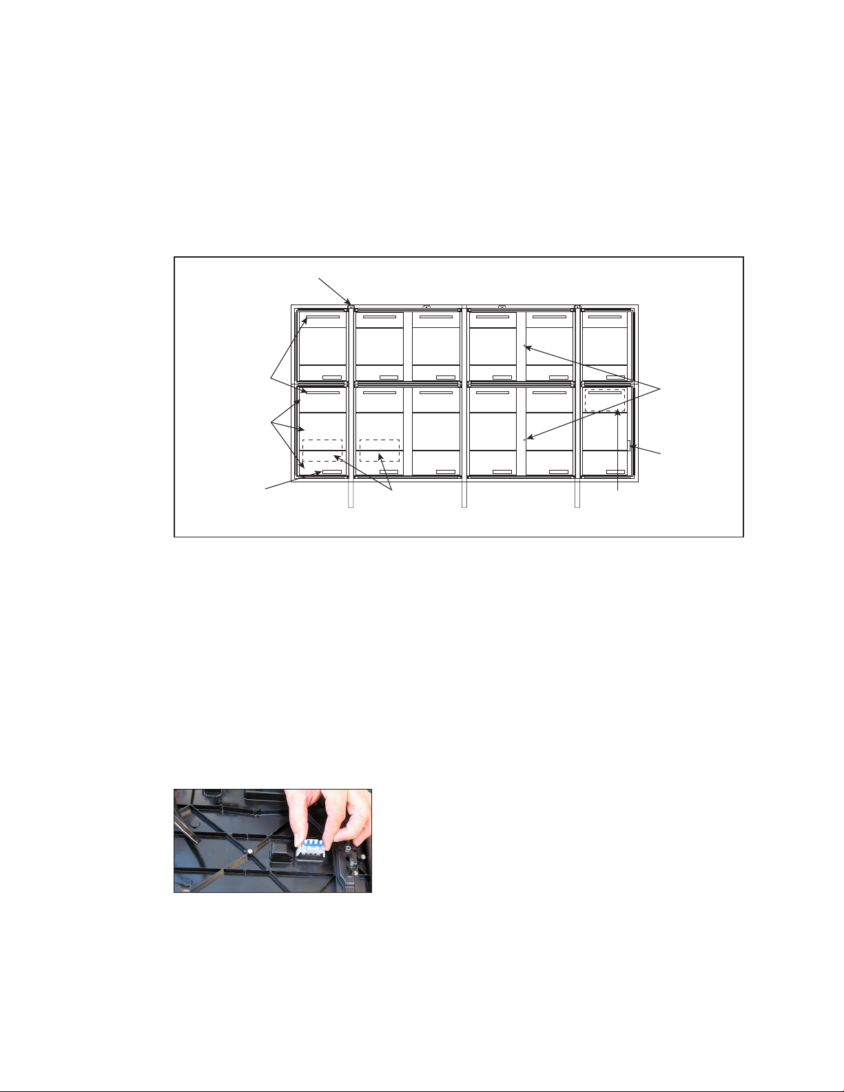
Module Lanyard Attachment ...........................................................................................................10
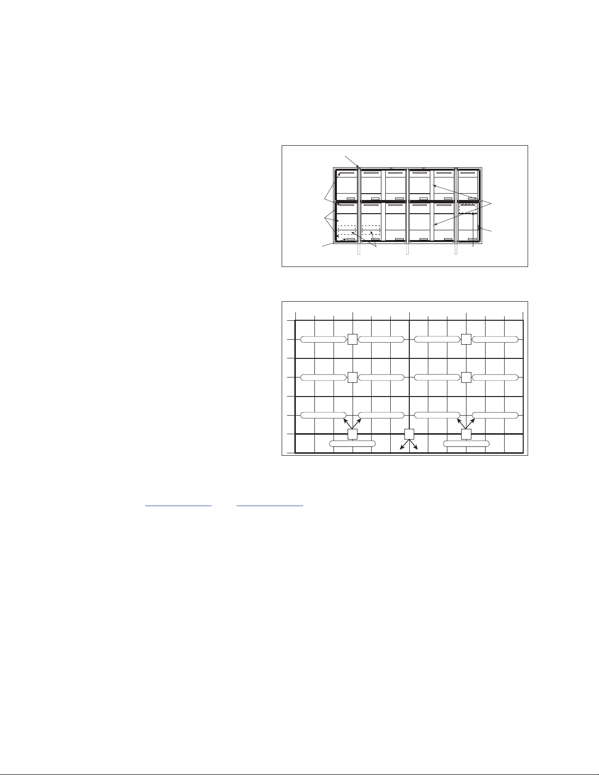
Remove a Module (Front Access)....................................................................................................10
Reinstall the Module (Front Access) .................................................................................................10
Remove a Module (Rear Access) ....................................................................................................11
Remove Fan Plenum..........................................................................................................................11
Remove a Module from Behind an ISP Enclosure ..........................................................................12
Remove the Optional SmartLinkTM For Module Access..................................................................12
Reinstall a Module (Rear Access).....................................................................................................12
6 Test and Replace Display Components ���������������������������������������������������������������������������14
Test a Module......................................................................................................................................14
Module Status Indicators ���������������������������������������������������������������������������������������������������������������14
Perform a Module Self-Test������������������������������������������������������������������������������������������������������������14
Replace Module Power Supplies......................................................................................................14
Test and Replace a ProLink Router...................................................................................................15
Test a PLR �����������������������������������������������������������������������������������������������������������������������������������������15
Replace a ProLink Router���������������������������������������������������������������������������������������������������������������16
Replace PLR Power Supplies ���������������������������������������������������������������������������������������������������������16
Replace a Display Fan�������������������������������������������������������������������������������������������������������������������16
7 Control Equipment Overview, Service, and Replacement ��������������������������������������������17
Open the ISP Enclosure......................................................................................................................17
Control Equipment Overview............................................................................................................18
ISP Enclosure �����������������������������������������������������������������������������������������������������������������������������������18
DMP-8000 ����������������������������������������������������������������������������������������������������������������������������������������18

– ii –
Table of Contents
iBoot Bar ������������������������������������������������������������������������������������������������������������������������������������������18
Connect a Laptop .............................................................................................................................19
Replace Control Equipment .............................................................................................................19
Replace the DMP-8000 ������������������������������������������������������������������������������������������������������������������19
Replace DMP/VIP Power Supply���������������������������������������������������������������������������������������������������19
Replace the ISP Enclosure Filter ����������������������������������������������������������������������������������������������������20
Replace the Router�������������������������������������������������������������������������������������������������������������������������20
Replace the Ethernet Switch ���������������������������������������������������������������������������������������������������������20
Replace the iBoot Bar ��������������������������������������������������������������������������������������������������������������������20
Replace the SmartLinkTM (Optional)����������������������������������������������������������������������������������������������21
Replace the Heater������������������������������������������������������������������������������������������������������������������������21
8 Test and Replace the Multi-Direction Light Sensor ����������������������������������������������������������22
Test the MDLS ......................................................................................................................................22
Replace the MDLS..............................................................................................................................22
9 Access and Troubleshoot the Webcam���������������������������������������������������������������������������23
Retract the Webcam to the Display Face (Rotation Mount Only)...............................................23
Troubleshoot the Webcam................................................................................................................23
10 Display Maintenance���������������������������������������������������������������������������������������������������������24
Service Calls ........................................................................................................................................24
Annual Inspection ..............................................................................................................................24
Glossary�������������������������������������������������������������������������������������������������������������������������������������25
A Reference Documents �������������������������������������������������������������������������������������������������������27
B Daktronics Warranty and Limitation of Liability ���������������������������������������������������������������29

Introduction
1
1 Introduction
Important Contact Information
Daktronics Customer Service: 1-800-DAK-TRON (325-8766)
Project Manager: Phone Number:
Email: [email protected]
Display Identication
This section provides information that is helpful
in understanding a Daktronics digital billboard
display label. Refer to Figure 1 while reading the
table below.
Display Assembly Number
Display Serial Number
Manufacture Date
(Day/Month/Year)
BLD-0X00 Modules High X Modules Wide
RMN: Daktronics - 0200 - 12 Manufactured in Sioux Falls, SD
120/240 VAC, Single Phase, 60 HZ
Amps (L1/L2)
Total Watts
Spare Parts
Every Daktronics digital billboard is shipped with
spare parts that include commonly replaced
components. The table lists some of the
components that may be included in the spare
parts rack. Refer to Figure 2. Refer to the spare
parts inventory list contained in the bag in the
spare parts rack for a list of the parts. Contact
the Account Service Manager (ASM) to order
additional spare parts.
Spare parts are located inside the display cabinet
behind the bottom-left doors. Refer to Figure 3.
Description
Power Supply
Module
Power Supply
Air Filter
Fuse
4-Pin Mate-N-Lok Plug
Splice Tool (Sectional Displays Only)
28" SATA Cable
72" SATA Cable
Figure 1: BLD Series Display Label
Figure 2: Spare Parts in Spare Parts Rack

Introduction
2
Locate the Spare Parts Rack
Spare parts are located inside the display cabinet behind the bottom-left rear door.
Refer to Figure 3.
Open and Remove the Spare Parts Rack
1� Remove the Torx head tap screws on top of the spare parts rack.
2� Gently pull the rack downward. Refer to Figure 2.
3� Support the rack to keep it from falling.
Section 200
Section 100
Display Front
Display Rear
3" Border
Painted All
Around
Lift Eye
Power
Entrance
Signal
Entrance
Internal Control
System
Ventilation
Intake
Ventilation
Exhaust
Doors
Spare
Parts
Support
Ledger
Figure 3: Spare Parts Rack in Display
4� Lift the rack upward and outward to remove it from the display enclosure.
Remove a Module From Spare Parts Rack
1� With one hand on the module face, insert the 1/8" hex head wrench into the bottom
access hole.
2� Turn the latch release approximately a quarter-turn counterclockwise. You should feel
the module release from the display face.
3� Disconnect the SATA cables from the back of the module.
4� Remove the plug inserted into the power jack. Refer to Figure 4. Store the plug and
cable in an area free of debris for future use with replacement modules.
Figure 4: Remove Plug From
Power Jack on Spare Module

Introduction
3
Field-Replaceable Units
The table below lists names of components that can be replaced in the display and the
control system. Some of these components are located in the spare parts rack. Contact
the ASM to order components when needed.
Display FRUs Control System FRUs
ProLink Router Temperature Sensor
Line Filter VIP-5160.2
Power Supply Light Sensor - MDLS
Module Ethernet Switch
Axial Fan .4 A 115 Volt Mobotix Webcam
12 VDC Relay iBoot Bar
Two Pole Relay 500 W Heater
28" SATA Cable DMP-8000 Player
72" SATA Cable 60 V Surge Protector
SmartLinkTM (Optional)
Meraki Router
Axial Fan .16 A
Filter

Display and Control Overview
4
2 Display and Control Overview
This section describes generic power and signal paths for Daktronics digital billboards.
Refer to display-specic signal and riser drawings for component locations on your
display.
Display Control System Flow Overview
Figure 5 shows the location of the
internal control system and the
remote power control device. The
control system bay or components
may vary slightly by display. Refer
to project-specic drawings for
display control location, signal
path, and power path.
Display Power
Overview
Each 400 W power supply powers
12 modules in BLD series billboards.
In most cases, the module power
path follows the signal path.
Figure 6 shows a basic overview of
the power system in an individual
display section.
Power to the display section enters
into the power entrance and is
redistributed to the power supplies.
Refer to the layout drawing for
display-specic power distribution.
Display Signal
Overview
Refer to DWG-4118208 and DWG-4118209 for display-specic signal routing.
Signal is sent from the DMP-8000 to the VIP-5160. The VIP-5160 sends signal to the PLR,
which sends the signal to the rst module in the section. From that module, the signal is
sent to the other modules in the section. The PLR not only sends signal to the rst module
in the chain but also receives signal from the last module in the chain and creates a
redundant signal path.
Section 200
Section 100
Display Front
Display Rear
3" Border
Painted All
Around
Lift Eye
Power
Entrance
Signal
Entrance
Internal Control
System
Ventilation
Intake
Ventilation
Exhaust
Doors
Spare
Parts
Support
Ledger
Figure 5: BLD Series Component Locations
PS PS
PS PS
PS PS
PS
30" MOD WHIP 30" MOD WHIP 30" MOD WHIP 30" MOD WHIP
60" MOD WHIP 60" MOD WHIP
Bay 1 Bay 2 Bay 3 Bay 4
C
R1 2 3 4 5 67 8 910 11 12
1
2
3
4
5
6
7
Figure 6: Power Example - Poster (11' x 22') Display

Troubleshoot the Display
5
3 Troubleshoot the Display
Remotely Cycle Power
Daktronics BLD series displays ship
with an iBoot PDU or optional
SmartLinkTM for remote control of
the display and components. The
remote power device has four
circuits for interdependent control
of various components as shown
in the following table. The remote
power device monitors equipment
and can attempt recovery of non-
responsive equipment.
Circuits Component
1 ISP Enclosure
2 DMP-8000/VIP-5160.2
3 Display
4
If remote troubleshooting is desired, call Daktronics customer service at 1-800-DAK-TRON
(325-8766) for assistance. Do not cycle power to the components because it can take as
long as an hour to reset the circuits.
Troubleshoot the Display
Work with Daktronics help desk or experienced technicians to address display issues.
Refer to the following table for troubleshooting steps.
Issue Issue Image Troubleshooting Steps
Entire display
blank
1. Verify there is power to site by ensuring
the power supply indicators are on. If they
are on, there is power to site and it is most
likely a signal issue. If there is site power,
continue to Step 3.
2. Verify the relays for each display section
are closed and allowing power to the
display and control system.
3. Verify the ProLink Router (PLR) is receiving
power. If the LED indicator lights are on,
unplug and reestablish power to the PLR.
4. Verify the ber cables from the Digital
Media Player (DMP) to the PLR are
connected.
5. Call Daktronics customer service at
1-800-DAK-TRON (325-8766) to verify the
content that was supposed to play was
successfully uploaded / sent to the display.
Figure 7: iBoot

Troubleshoot the Display
6
Issue Issue Image Troubleshooting Steps
Content
switched
between display
sections
1. Check the ber interconnect cables
between the display sections because
they may be switched. Port A should be
connected to Port A. Port B should be
connected to Port B.
2. Check the ber cables coming from the
DMP because they may be switched.
Scattered or out
of order content
1. The SATA cable and redundant SATA
cable from the PLR to the modules may be
switched.
2. Call Daktronics help desk to verify the
translation table is correct.
Area of content
mixed up -
module ID out of
order
Verify the SATA cable path in that area is
correct by comparing it to the display signal
drawing. If not, correct the signal path.
Display too
bright
1. Immediately call Daktronics help desk and
have them blank the display.
2. Verify the Multi-Direction Light Sensor
(MDLS) is connected.
3. Inspect the area for a light source shining
on the Multi-Direction Light Sensor (MDLS).
This may cause incorrect readings. If
necessary, relocate the MDLS to a different
area.
4. Verify the MDLS is mounted correctly. If
not, remount the MDLS.
5. Have the help desk verify that the MDLS is
set to multi-direction and automatic.
Display too dim
1. Verify the MDLS is connected.
2. Verify the MDLS is mounted correctly. If
not, remount the MDLS.
3. Verify there is no debris or excessive dirt
buildup on the three MDLS windows.
4. Have the help desk verify that the MDLS is
set to multi-direction and automatic.
5. Have the help desk verify the display is
not experiencing thermal dimming due to
excessive heat.

Troubleshoot the Display
7
Issue Issue Image Troubleshooting Steps
Blank display
section
1. If applicable, verify the ber interconnects
are installed.
2. On displays with multiple sections or
power entrances, verify the relay signal
interconnect cables between the power
entrances are connected.
3. Check the modules at the beginning and
end of the affected area. This issue can
be caused by disconnected or bad SATA
cables on both of those modules. If the
module power indicator is on, there is most
likely a SATA cable issue. If the module
power indicator light is off, there is most
likely a module issue.
4. Measure site power and verify it meets
the requirements listed on the system
riser. If this issue appears when there is
white or light content, it is possible there
is insufcient power to the display. If this
is the case, work with an electrician to
establish the correct site power.
5. Verify the PLR has power and is
functioning. Disconnect and reconnect
power to the PLR.
6. Verify there is power to that display section
by checking module status indicators on
multiple modules. If there is no power,
check the power entrance on that
section.
7. Check that the relays in each display
section are closed which means that
section should be receiving power.
1 module out
1. Ensure the SATA and power cables to the
module are connected and secure.
2. A SATA cable may be damaged. Replace
both SATA cables to the module to see if
this addresses the issue.
3. It is likely a bad module. Swap the module
with a replacement module and verify
that the new module functions correctly.
12 modules out
1. Check the status indicators on the rear
of the modules. If the indicators are off,
check the power indicator on the power
supply for the affected modules. If the
power supply indicator is off and there is
power connected to the power supply,
replace the power supply.
2. If there is power to the power supply and
the modules, check the SATA cables to
the modules. It is possible the SATA cables
at the beginning and end of the affected
modules are disconnected or bad.

Troubleshoot the Display
8
Issue Issue Image Troubleshooting Steps
3 or more
modules out
in a line within
the same PLR
section
1. Check the modules at the beginning and
end of the affected area. This issue can
be caused by disconnected or bad SATA
cables on both of those modules. If the
module power indicator is on, there is most
likely a SATA cable issue. If the module
power indicator light is off, check the
power supplies for the modules at each
end of the issue are on. If not power or
signal, it is most likely a module issue.
2. Measure the site power to verify it meets
Daktronics requirements. If this issue is only
seen with white or light-colored content,
there is most likely a power issue. If there is
insufcient power, work with an electrician
to establish proper site power.

Access Internal Components
9
4 Access Internal Components
Rear Access
BLD series digital billboards have lift-off doors that
are secured with a tab in the top-left corner. Refer
to Figure 8.
1� Place ngers in the slot located at the top-left
corner of the door. Refer to Figure 9.
2� While pulling up on the handle in the center of
the door, pull the top-left corner of the door
outward so it clears the tab located on the
display back sheet. Refer to Figure 9.
3� Lift the door upward to disengage its tabs
from the slots on the display’s back sheet.
Refer to Figure 10.
4� Lower door until its top lip is free.
To completely move the door out of the way,
disconnect the lanyard connected to the door.
Front Access
Remove modules from the display front to gain
access to the cabinet’s interior. Refer to the steps
in Remove a Module (Front Access) (p�10).
Figure 8: Rear Access Door
Figure 9: Removing Door
Figure 10: Removing Door

Test and Remove Modules
10
5 Test and Remove Modules
Module Lanyard Attachment
Attach a module lanyard (located in the spare parts
rack) whenever removing a module. To attach a module
lanyard, follow these steps:
1� Attach one end of the lanyard to an attachment ring
on the top of the of the module. Refer to Figure 11.
2� Feed the lanyard over a wire rod or through a nearby
upright. Do not anchor the module to another
module.
3� Attach the other end of the lanyard to the
attachment ring on the top of the module.
Remove a Module (Front Access)
Required Tools: 1/8" hex head wrench, module lanyard (from the spare parts rack)
1� Insert the 1/8" hex head wrench into the top access
hole. Refer to Figure 12.
2� Turn the latch release approximately a quarter-
turn counterclockwise. You should feel the module
release from the display face.
3� Pull the module from the display face just far enough
to reach the back of the module.
4� Disconnect the power and SATA cables from the
back of the module.
5� Gently place the module on a clean and dry surface.
Note: If there is no place to set the module, use a safety lanyard to hang the
module from the rear of the display. Attach the safety lanyard in a way that
takes up slack on the lanyard. Carefully let the module hang while ensuring it
does not damage the LEDs, louvers, or gasket.
Reinstall the Module (Front Access)
When installing new modules, place them in the outer ring of the display.
1� Reinstall the module by aligning it with the opening.
2� Reattach the power and SATA cables.
3� Carefully hook the module into the module sheet and rotate the module top to the
module sheet. Verify that SATA and power cables are not being pinched between
the module and display face.
4� Firmly press the upper half of the module against the display face.
5� Insert the 1/8" hex head wrench into the bottom access hole and turn approximately
a quarter-turn clockwise or until you feel it latch in place.
Figure 11: Attach Safety Lanyard
to Modules
Access
Hole
Figure 12: Module Access Hole

Test and Remove Modules
11
6� Insert the 1/8" hex head wrench into the top access hole and turn approximately a
quarter-turn clockwise or until you feel it latch in place.
7� Gently pull on the module to verify it is properly
seated.
Remove a Module (Rear Access)
Required Tools: 1/8" hex head wrench, or 1/8" L-handle
hex head wrench for modules in the bottom or top rows
of a section, module lanyard (from the spare parts rack)
1� Attach one end of the safety lanyard to a lanyard
ring on the top of the module. Refer to Figure 11.
2� Feed the lanyard through the lanyard ring on the top
of the display directly below the module that will be
removed.
3� Attach the other end of the lanyard to the lanyard
attachment ring on the bottom of the module that
will be removed. Refer to Figure 11.
4� Disconnect the SATA and power cables from the
back of the module.
5� With a 1/8" hex head wrench, turn the bottom latch
gear approximately a quarter-turn clockwise to
disengage the latch.
6� With a 1/8" hex head wrench, turn the top latch gear
approximately a quarter-turn clockwise to disengage
the latch.
Note: Maintain a rm grip on the module as it is
removed from the face sheet.
7� Rotate the module in a way that allows you to guide
it through the frame opening without catching the
louvers or LEDs on the cabinet. Figure 13 shows proper
module removal from the rear. Figure 14 shows
improper module removal from the rear.
Remove Fan Plenum
Fan plenums may need to be removed because they
restrict access to modules in the bottom row of each
section.
1� Disconnect the power harness attached to the fan.
Refer to Figure 15.
2� Press inward on the bottom of each side of the fan
plenum. Refer to Figure 16.
3� When the plenum tabs disengage, gently pull the
plenum upward and remove it from the display. Refer
to Figure 17.
4� Reverse Steps 1–3 to reinstall the fan plenum.
Figure 13: Proper Module
Removal From Back
Figure 14: Improper Module
Removal From Back
Figure 15: Fan Power Harness
Figure 16: Removing Fan Plenum
Figure 17: Fan Plenum Tab

Test and Remove Modules
12
Remove a Module from Behind an ISP Enclosure
Required Tools: 1/8" hex head wrench, module lanyard
1� Remove pins from one side of the control enclosure.
Refer to Figure 18.
2� While holding the ISP enclosure, allow it to slowly
rotate open and out of the way. Refer to Figure 19.
3� Follow the steps in Remove a Module (Rear Access)
(p�11) to remove a module and Reinstall a Module
(Rear Access) (p�12) to reinstall a module.
4� If needed, remove all pins that hold the control
enclosure in place in the cabinet. Lift the control
enclosure out of the cabinet and set aside while
ensuring power and signal cables do not get
pinched.
5� Reverse Steps 1–4 to replace the ISP enclosure.
Remove the Optional SmartLinkTM
For Module Access
The SmartLinkTM, if equipped, swings out of the way for
module access.
1� Remove the pins from one side of the SmartLinkTM.
2� While holding the SmartLinkTM enclosure, allow it to
slowly rotate open and out of the way.
3� If needed, remove all the pins from the other side of
the SmartLinkTM, carefully lift the SmartLinkTM out of the
enclosure and set aside while ensuring power and
signal cables do not get pinched.
Reinstall a Module (Rear Access)
When installing new modules, place them in the outer ring of the display.
1� Rotate and carefully guide the module through the
module opening. Refer to Figure 20.
Note: To ensure proper alignment, verify the word
TOP printed on the back of the module is to
the top left of the face sheet.
2� Once the module is through the display face, align
the module with the face sheet. Ensure the lanyard
or cables do not pinch between the module and the
display.
3� After the module is in place, use the bottom module
lanyard rings or the lanyard to pull the module rmly
against the face sheet.
4� With a 1/8" hex head wrench, turn the bottom latch gear approximately a quarter-
turn counterclockwise to engage the latch.
Figure 18: Remove Pins
Figure 19: Swing ISP Enclosure
Out of Display
Figure 20: Rotate Module To
Clear Face Sheet

Test and Remove Modules
13
5� Use the top module lanyard rings or the lanyard to pull the module rmly against the
face sheet.
6� With a 1/8" hex head wrench, turn the top latch gear approximately a quarter-turn
counterclockwise to engage the latch.
7� Connect the SATA and power cables to the back of the module.

Test and Replace Display Components
14
6 Test and Replace Display Components
Test a Module
Module Status Indicators
Under normal operation, module indicator LEDs
(one on each side on the back of the module)
should ash once every two seconds. Refer to
Figure 21.
Note: When troubleshooting, it is important to
know that the module may take up to
eight seconds to change the pattern.
Perform a Module Self-Test
If a module is blank, but has power supplied to it,
perform a module self-test to diagnose a module
or SATA cable failure. To perform a self-test, follow
these steps:
Visit youtu.be/M61KEMAOdaM to view a video
about performing a module self-test.
1� Attach a SATA cable to Port A and Port B on
the module. Refer to Figure 22.
2� Disconnect the power to the power supply for
10 seconds.
3� Reconnect the power to start the self-test.
4� Verify the module is running a self-test.
Remove the SATA cable and cycle power to the
module to stop the self-test.
For more information, refer to Performing a Daktronics Digital Billboard Module Self Test
(DD1944805) in Appendix A: Reference Documents (p�27).
Replace Module Power Supplies
The power supply provides power from the power entrance to
the module. For BLD series digital billboards, the module power
supply is located on the uprights. Each power supply typically
controls 12 modules.
1� Disconnect the power coming from the power entrance to
the power supply.
2� Disconnect the power cables from the power supply to the
modules. Refer to Figure 23.
3� While holding the power supply against the upright, rotate
the power supply bracket release tab counterclockwise off
of the power supply.
4� Gently lift the power supply assembly off the upright.
LED Status
Indicators
SATA
(Signal)
Jacks
Power
Jack
Figure 21: Labeled Module Back
Figure 22: Module Self-Test
Figure 23: Power Supply
Mounted to Upright

Test and Replace Display Components
15
Test and Replace a ProLink Router
A ProLink Router (PLR) sends the signal from the DMP-8000 to
the modules via SATA cables.
Visit youtu.be/DnoPC1OYhv0 to view a video about testing
and replacing a ProLink Router.
Test a PLR
Before replacing a PLR, it may be benecial to perform a self-
test. To test a PLR, follow these steps:
1� Connect a duplex ber cable from Fiber Port A to Fiber
Port B. Refer to Figure 24.
2� Connect a working SATA cable from SATA Port A to SATA Port B.
3� Connect the power cable to the PLR. This will start the PLR self-test.
4� Wait for the test to complete. This may take up to 90 seconds. If the PLR successfully
sends and receives data through each of the ports, the letters P.A.S will appear on
the Seven Segment Display. If the letters E.r.r appear, the Seven Segment Display will
show the port numbers with issues. Refer to the ProLink Router 6X5X Installation and
Maintenance Manual (DD1735784) in Appendix A: Reference Documents (p�27) for
a list of error codes.
The PLR outputs test patterns in a specic order starting with Red, Green, Blue, and
White. The PLR sends out these patterns with full redundancy (out both port A & B at
the same time). If all of the modules change
colors, it shows they all work and that visually
the display is ne, but there could still be a
signal failure that will not show up visually
because of redundancy. The Amber/Yellow
and Magenta test patterns provide a way to
nd the normally non-visual breaks.
After it shows the White test pattern, the PLR
shows a Yellow pattern, but it only sends the
that pattern out on port A (no redundancy),
any modules that receive that command will
turn Yellow. However, if there is a signal break,
the modules will not receive the command to
turn Yellow and will remain at their previous
color, which was probably White. Refer to
Figure 25. The modules that turn Yellow are
working correctly. Modules that are not Yellow
indicate where the signal break is. If all of the
modules turn Yellow, it indicates the signal
path in the “A” direction is working 100%.
After showing the Yellow pattern, the PLR
shows the Magenta pattern, but it only sends
that pattern out on Port B. Any modules that
do not receive the magenta command
will remain at their previous color, which is
probably Yellow. Refer to Figure 26. Wherever
they do not turn magenta indicates a signal
break. If they all turn Magenta, it means the
signal path in the “B” direction is 100%.
5� Replace the PLR if the error persists after troubleshooting.
Figure 24: ProLink Router
Connected For Self-Test
Figure 25: ProLink Router Port A Test
Figure 26: ProLink Router Port B Test

Test and Replace Display Components
16
Note: It is possible to have a break in just one path. So for example, it is possible all of
the modules may turn Yellow indicating “A” is healthy, but only some of them
turn Magenta indicating a break in the “B” path that needs to be repaired.
Replace a ProLink Router
Required Tools: Phillips screwdriver
1� Access the interior of the display by following the steps provided in Section 4: Access
Internal Components (p�9).
2� Disconnect the PLR SATA and power cables.
3� Use a Phillips screwdriver to loosen the PLR assembly set screw.
4� Lift the PLR assembly to disengage it from the display.
5� Reverse Steps 2–4 to install the new PLR.
6� Verify the cables are properly seated.
Replace PLR Power Supplies
1� Disconnect the power supply from any wiring
harnesses connected to it.
2� Push down on the top leg of the wire form bracket
and rotate the power supply clockwise. Refer to
Figure 27.
3� Carefully pull the power supply outward.
4� Secure the new power supply in the bracket.
5� Rotate the bracket back into place inside the
cabinet.
6� Reconnect the wiring harnesses disconnected in
Step 1.
Replace a Display Fan
Required Tools: Side cutter, cable ties
If needed, remove the fan plenum following the
steps in Remove Fan Plenum (p�11)�
1� Locate and disconnect the 3-pin Mate-N-Lok
connector.
2� Push in on the sides of the nger guard and
rotate it to remove the fan. Refer to Figure 28.
3� Cut the cable tie holding the harness to the
plenum.
4� Remove the fan from the display.
5� Reverse Steps 1–4 to install the new fan.
6� Attach harness to the fan plenum using a cable tie. Refer to Figure 28.
Figure 27: PLR Power Supply
Mounting
Figure 28: Display Fan
Table of contents