manuals.online logo
Brands
  1. Home
  2. •
  3. Brands
  4. •
  5. Daktronics
  6. •
  7. Monitor
  8. •
  9. Daktronics PPX-1050 Series User manual

Daktronics PPX-1050 Series User manual

PPX-1050 Series Panel Installation & Service Quick Guide Page 1 of 3
DD5004860
Rev 00
05 January 2022
201 Daktronics Drive
Brookings, SD 57006-5128
www.daktronics.com/support
800.325.8766
Basics
Display Accessories
Standard display accessories include the following:
• Lifting tool
• Key
• Power input cable
• Signal input cable
Figure 1: Lifting Tool Figure 2: Key
Figure 3: Power Input Cable Figure 4: Signal Input Cable
Storage & Shipping
Panels are stored and shipped in
wood crates with four panels per
crate. The depth of the crate is
980 mm, and the height and width
vary by panel size. Refer to the table
below and Figure 5.
Crate Size Panel Size
940x1240 mm 640x1120 mm
940x1400 mm 640x1280 mm
1100x1240 mm 800x1120 mm
1100x1400 mm 800x1280 mm Figure 5: Wood Crate
980 mm
940 or 1100 mm
1240 or 1400 mm
Mechanical Installation
Panel Installation
Note: Two people are required for the steps in this section.
1. Use a pry bar to remove the crate lid, exercising caution to prevent
damage to the LED panels in the crate. Refer to Figure 6.
Figure 6: Remove Crate Lid Figure 7: Remove Crate Side
2. Use a pry bar to remove the crate side, exercising caution to prevent
damage to the LED panels in the crate. Refer to Figure 7.
3. Use the supplied lifting tool as an additional handle and remove the
panel from the crate. Refer to Figure 8.
Figure 8: Remove Panel from Crate Figure 9: Stand Panel on Ground
4. Use the side handles on the panel to stand the panel upright on the
ground. Refer to Figure 9.
5. Verify the existing jump cable on the panel is a female-to-male
connection. Refer to Figure 10 and Figure 11.
Figure 10: Female Connector Figure 11: Male Connector
6. Use the supplied key to unlock the top locks and slide the top cover
back to remove the cover. Refer to Figure 12 and Figure 13.
Figure 12: Unlock Top Locks Figure 13: Remove Top Cover
7. Use the lifting holes to lift the panel. Refer to Figure 14 and Figure 15.
Figure 14: Lift Panel
8. Repeat Steps 3-7 for any additional panels.
45°
minimum
Figure 15: Lift Panel
PPX-1050 Series Panel Installation & Service Quick Guide Page 2 of 3
DD5004860
Rev 00
05 January 2022
201 Daktronics Drive
Brookings, SD 57006-5128
www.daktronics.com/support
800.325.8766
Panel-to-Panel Connection
1. Place two panels side-by-side on the wall and secure the panels
together with M10 screws and nuts at three xing points on the side of
each panel. Refer to Figure 16 and Figure 17.
Figure 16: Secure Panels Together
2. Route power and signal cables
between panels directly from the top.
Electrical Installation
Signal Connection
A DVI cable connects a computer located in the control room to a
sending box. Some sending boxes may have additional signal input
options, such as HDMI and SDI. The sending box passes signal via a
Cat 5e/Cat 6 cable into the receiver card located inside the rst panel.
Each panel has a receiver card, and Cat 5e/Cat 6 cables daisy-chain the
receiver cards together. The last panel can connect back to the sending
box for redundant data to the receiver cards if desired.
1. Connect the sending box to the computer with a DVI cable. Refer to
Figure 18 and Figure 19.
Figure 18: Sending Box (Front)
Figure 19: Sending Box (Rear)
2. Connect a Cat 5e/Cat 6 cable from the sending box RJ45 output jack
to the RJ45 quick-connect jack in the rst panel. Refer to the
contract-specic Riser Diagram.
Figure 17: M10 Fastener (Front View
with Module Removed)
Note: The maximum cable distance from the sending box to the rst receiver
card is 328.08' [100 m]. For installations exceeding this distance, use
a ber converter to convert the Cat 5e/Cat 6 cable to a ber cable,
which offers an additional 984.25' [300 m] with multi-mode ber or up
to 9.32 mi [15 km] with single-mode ber. Two ber converters can be
used to convert the cable to a ber cable and then back to a
Cat 5e/Cat 6 cable. The cable can connect to the rst panel. Use
additional cables to connect to the next panel. Refer to Figure 20 and
Figure 21.
Figure 20: Fiber Cable
3. Route the Cat 5e/Cat 6 cable from
the signal output jack to the signal
input jack on the next panel. Refer
to Figure 22 and the Riser Diagram.
Figure 22: Route Cables
Sending box Fiber converter Fiber
Cat 5e/Cat 6 Fiber converter
Cat 5e/Cat 6
Note: Routing may vary based on converter type.
4. Connect the last panel back to the sending box for redundant signal
connection if desired.
5. Refer to the NovaStar®LED Display Control System M3 User’s Manual for
details on how to congure the system and run the display.
Refer to Figure 23 for an example of six panels connected together.
Sending box
Primary
Redundant (optional)
Figure 23: Connect Signal
Power Connection
Most standard panels come with power quick connects with
pre-terminated connectors at each end.
The gender is different for the power input and output ends. Power
interconnect cables are shipped with the displays. Typically, every six
panels needs a new power input cable. Refer to the contract-specic Riser
Diagram for more details.
Figure 21: Fiber Converter
The main power input cable has a pre-terminated connector at one
end and bare wires at the other end. Only horizontal interconnects are
available. Refer to Figure 24.
To main CIR #1
Figure 24: Route Power Cables
Service
Note: Avoid exposing the contents of the power/signal box to moisture,
as the components are not sealed for water exposure.
Module Removal
1. Disconnect power to the display.
2. Unlock the top locks and slide the cover back to remove the top cover.
Refer to Figure 12 and Figure 13.
3. Use the handle at the top of the module to slide the module up and
out of the panel. Refer to Figure 25 and Figure 26.
Figure 25: Slide Module Up
4. Use a screwdriver to remove the four screws connecting the module
cable and then disconnect the cable. Refer to Figure 27 and Figure 28.
Figure 27: Remove Module Cable
Screws
Figure 28: Disconnect Module
Cable
Figure 26: Slide Module Out
PPX-1050 Series Panel Installation & Service Quick Guide Page 3 of 3
DD5004860
Rev 00
05 January 2022
201 Daktronics Drive
Brookings, SD 57006-5128
www.daktronics.com/support
800.325.8766
4. Use a screwdriver to remove the
screws securing the fan to the hub
board. Refer to Figure 39.
5. Pull the fan gently outward to
remove it from the hub board.
Reverse these steps to install a fan.
Power Supply Removal
1. Disconnect power to the display.
2. Disengage the three latches on the
power box to open the box. Refer to
Figure 33.
3. Locate the power supply to be removed. Refer to Figure 40.
Figure 40: Power Supplies in Power Box
4. Remove the cables and mounting hardware from the power supply.
Refer to Figure 41 and Figure 42.
Figure 41: Remove Cables from
Power Supply
Figure 42: Remove Hardware from
Power Supply
5. Use a screwdriver to remove the nuts securing the power supply to the
power box and then remove the power supply. Refer to Figure 43.
Figure 43: Remove Nuts from Power
Supply
Reverse these steps to install a power supply, placing a thermal pad on the
rear of the new power supply before mounting. Refer to Figure 44.
Figure 44: Thermal Pad on Power
Supply
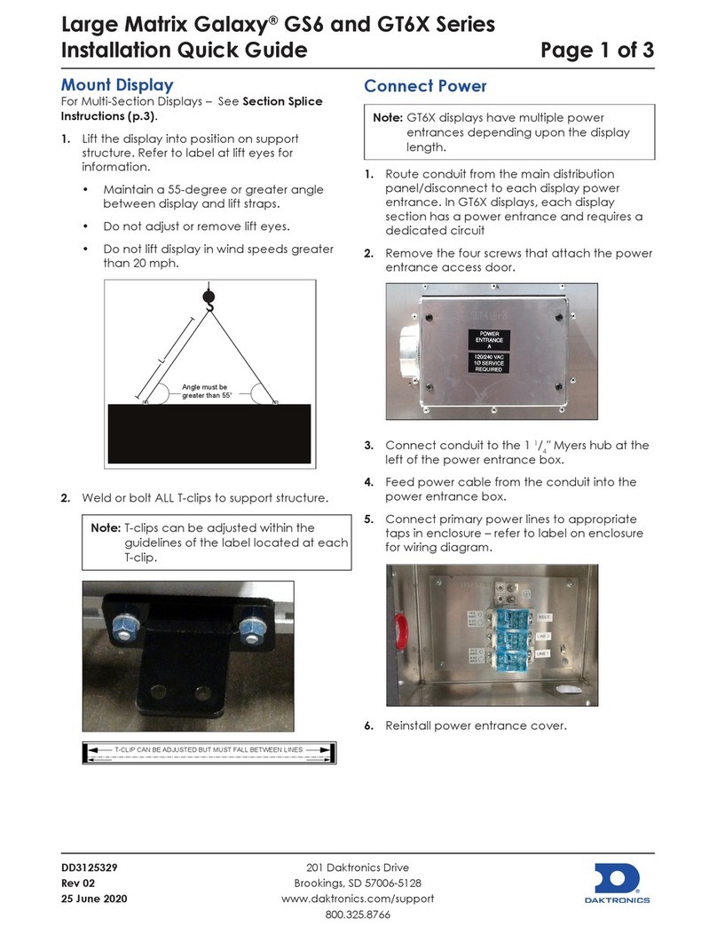
5. Remove the module. Refer to Figure 29.
Figure 29: Remove Module
Reverse these steps to install a module, aligning the connector on the
module with the corresponding slots on the panel and reconnecting the
cable connector on the module. Refer to Figure 30 and Figure 31.
Receiver Card Removal
1. Disconnect power to the display.
2. Use the handles to pull the power box up and disengage the three
latches on the power box. Refer to Figure 32 and Figure 33.
Figure 32: Use Handles to Pull Power
Box Up
Figure 33: Disengage Latches on
Power Box
3. Rotate the box over the top of the panel and open the box. Refer to
Figure 34 and Figure 35.
Figure 34: Rotate Power Box Figure 35: Open Power Box
Figure 30: Module Connectors
Figure 31: Install Module
4. Remove the screws securing the
receiver card to the hub board.
Refer to Figure 36.
5. Pull the receiver card gently outward
to remove it from the hub board.
Reverse these steps to install a receiver
card, sending the cong le from the
sending box after the new receiver card
is installed.
Hub Board Removal
1. Disconnect power to the display.
2. Disengage the three latches on the power box to open the box. Refer
to Figure 33.
3. Remove the receiver card. Refer to Step 4 and Step 5 in Receiver Card
Removal (p.3) and Figure 37.
Figure 37: Remove Receiver Card & Disconnect Power & Signal Cables
4. Disconnect the power and signal cables from the hub board. Refer to
Figure 37.
5. Use a screwdriver to remove the screws securing the hub board to the
power box. Refer to Figure 38.
Figure 38: Remove Screws from Hub Board
6. Pull the hub board gently outward to remove it from the power box.
Reverse these steps to install a hub board.
Fan Removal
1. Disconnect power to the display.
2. Disengage the three latches on the power box to open the box. Refer
to Figure 33.
3. Disconnect the fan cable from the hub board. Refer to Figure 39. The
fan is mounted to the right hub board.
Figure 36: Remove Screws Figure 39: Disconnect Fan Cable
& Remove Screws Securing Fan to
Hub Board

Other Daktronics Monitor manuals

Daktronics Galaxy GS6 User manual

Daktronics

Daktronics Galaxy GS6 User manual

Daktronics FUELIGHT FL-3000 Series User manual

Daktronics

Daktronics FUELIGHT FL-3000 Series User manual

Daktronics Galaxy Series User manual

Daktronics

Daktronics Galaxy Series User manual

Daktronics ProPixel PSX-5102-62MN-10 User manual

Daktronics

Daktronics ProPixel PSX-5102-62MN-10 User manual

Daktronics Galaxy AF-3155 User manual

Daktronics

Daktronics Galaxy AF-3155 User manual

Daktronics DVX-2101 Series User manual

Daktronics

Daktronics DVX-2101 Series User manual

Daktronics Galaxy AF-3400 Series User manual

Daktronics

Daktronics Galaxy AF-3400 Series User manual

Daktronics VF-2400 GEN 2 Series User manual

Daktronics

Daktronics VF-2400 GEN 2 Series User manual

Daktronics 65 Series User manual

Daktronics

Daktronics 65 Series User manual

Daktronics Galaxy AF-3112 Primary Series User manual

Daktronics

Daktronics Galaxy AF-3112 Primary Series User manual

Daktronics Galaxy Series User manual

Daktronics

Daktronics Galaxy Series User manual

Daktronics VANGUARD VC6 User manual

Daktronics

Daktronics VANGUARD VC6 User manual

Daktronics SLD 110 User manual

Daktronics

Daktronics SLD 110 User manual

Daktronics Large Matrix Galaxy GT6X Series User guide

Daktronics

Daktronics Large Matrix Galaxy GT6X Series User guide

Daktronics SLD Series User manual

Daktronics

Daktronics SLD Series User manual

Daktronics DataTime DF-1012 User manual

Daktronics

Daktronics DataTime DF-1012 User manual

Daktronics NPN-4100 Series User manual

Daktronics

Daktronics NPN-4100 Series User manual

Daktronics Fuelight FL-4000 Series User manual

Daktronics

Daktronics Fuelight FL-4000 Series User manual

Daktronics FUELIGHT FL-3000 Series User manual

Daktronics

Daktronics FUELIGHT FL-3000 Series User manual

Daktronics SLD 110 User manual

Daktronics

Daktronics SLD 110 User manual

Daktronics Galaxy GS6 User manual

Daktronics

Daktronics Galaxy GS6 User manual

Daktronics LARGE MATRIX GALAXY GS6 Series User manual

Daktronics

Daktronics LARGE MATRIX GALAXY GS6 Series User manual

Daktronics Galaxy AF-3400 Series User manual

Daktronics

Daktronics Galaxy AF-3400 Series User manual

Daktronics ST-2373 Series User manual

Daktronics

Daktronics ST-2373 Series User manual

Popular Monitor manuals by other brands

Fujitsu Siemens Computers 3815 FA operating manual

Fujitsu Siemens Computers

Fujitsu Siemens Computers 3815 FA operating manual

Austin Hughes UltraView AP-K13 user manual

Austin Hughes

Austin Hughes UltraView AP-K13 user manual

ViewSonic VE170m user guide

ViewSonic

ViewSonic VE170m user guide

BenQ GL2250 Specifications

BenQ

BenQ GL2250 Specifications

WTI CLM-D20 user guide

WTI

WTI CLM-D20 user guide

Sharp BIG PAD PN-65HC1 Application guide

Sharp

Sharp BIG PAD PN-65HC1 Application guide

eMachines E15T user guide

eMachines

eMachines E15T user guide

Ikan D7w quick start guide

Ikan

Ikan D7w quick start guide

ViewSonic VA1930WM - 19" LCD Monitor Käyttöopas

ViewSonic

ViewSonic VA1930WM - 19" LCD Monitor Käyttöopas

Panasonic TH-50LFE6E operating instructions

Panasonic

Panasonic TH-50LFE6E operating instructions

Planar PS5500 Specifications

Planar

Planar PS5500 Specifications

Abus TVAC10031 user manual

Abus

Abus TVAC10031 user manual

X-Vision X17LCD manual

X-Vision

X-Vision X17LCD manual

Acer AL1716 user manual

Acer

Acer AL1716 user manual

ThinkGizmos TG661 user manual

ThinkGizmos

ThinkGizmos TG661 user manual

LG 34WN750 owner's manual

LG

LG 34WN750 owner's manual

Cura1 SeizureAlert 3010 quick start guide

Cura1

Cura1 SeizureAlert 3010 quick start guide

Gateway KX1563 quick guide

Gateway

Gateway KX1563 quick guide

manuals.online logo
manuals.online logoBrands
  • About & Mission
  • Contact us
  • Privacy Policy
  • Terms and Conditions

Copyright 2025 Manuals.Online. All Rights Reserved.