DALGAKIRAN Dryair DK User manual

Instructions Manual
Dryair DK
REFRIGERATED TYPE COMPRESSED AIR DRYERS
Dryair DK10 - Dryair DK260
Rev No:4

Dryair DK
REFRIGERATED TYPE COMPRESSED AIR DRYERS
Dryair DK10 - Dryair DK260
www.dalgakiran.com

EN12100-1:2011, EN12100-2:2011, EN1050, EN13857:2010,
EN378-1+A2:2012, EN60204-1:2010, EN60529:2003,
NEN-EN-IEC61000-6-1:2008,
NEN-EN-IEC61000-6-2:2008,
NEN-EN-IEC61000-6-3:2008/A1:2011,
NEN-EN-IEC61000-6-4:2008,
EN61000-3-2,
BS EN 13445-1:2009,
BS EN 13445-3:2009,
ISO 15609-2:2005,
ISO 15613-2006,
ISO 15614-6:2008
EC DECLARATION OF CONFORMITY
MIKROPOR
Org.San. Bol. Buyuk Selcuklu Blv.
No:4 06935 Ankara/ TURKEY
The Product: Refrigerant Air Dryer
Type: DryAir DK10 to DryAir DK260
Trade Mark: Mikropor Refrigerant Air Dryer
Serial No: 0113MA00001 to 5214MA99999
Which this declaration relates, are in conformity with the
provisions of the above directives using the following
principal standards,
In accordance with EC Machinery directives
2006/95/EEC (LVD), 2004/108/EEC (EMC)
Inspection certificate No:46,57 2006/42/EC.
Inspection Certificate No:47,58
Inspection Body :Bureau Vertias (2287)
We,
declare that, under our sole responsibility for manufacture
and supply, the products;
Volkan AYHAN
issued at Ankara,
on 02/01/2013
for Mikropor by
V.P. of Sales and Operations

TABLE OF CONTENTS
1. Important safety notes - Please read ....................... 1
1.1. Transportation ............................................................ 1
1.2 Positioning .................................................................. 1
1.3 Installation ................................................................... 1
1.4 Before operating ......................................................... 1
1.5 Maintenance by an engineer ...................................... 1
1.6 Maintenance by the user ............................................ 1
2.Introduction to the DryAir DK dryer .......................... 2
3.Operation ...................................................................... 4
4.Technical specifications ............................................. 7
5.Diagrams...............................................................................10
6.General Arrangements .............................................. 25
7. Main Settings .............................................................. 25
8. Spare parts................................................................... 26
9.Drawings...................................................................... 30
10.Components location..................................................42
11.Troubleshooting ........................................................ 43
12. Warranty .................................................................... 46

A) When operating the air dryer the operator must apply safe working methods and observe all local safety
instructions and relevant regulations.
B) Prior to installation, the dryer and the compressed air system are to be depressurized and disconnected
from the electrical main supply.
C) The user is responsible for safe operating conditions. Parts and accessories must be replaced if inspection
shows that safe operation cannot be assured.
D) Installation, operation, maintenance and repair are only to be authorized, trained and skilled engineers.
E) The minimum and maximum values stated must be observed, as well as all of the safety precautions described
in this manual.
F) If any statement in this manual does not comply with the local legislation, the strongest standard is to be applied.
1.1. Transportation
A) Use care and caution when transporting the dryer. Avoid dropping and other physical abuse.
B) A forklift can be used to transport the dryers provided the forks are long enough to support its full width or
length and caution is used throughout the move.
1.2. Positioning
A) The dryer must be installed horizontally. A minimum of 50 cm clearance around the dryer is necessary to
allow a good ventilation and easy access for servicing.
B) The ambient temperature in the room should not exceed 50°C and should not be below 4°C, taking the heat
radiated by the dryer into account.
C) (40 watt for each liter/sec under ISO 7183-A condition or 18 watts for each SCFM under ISO 7183-B condition).
1.3. Installation
A) In addition to the general mechanical construction procedures and local regulations, the following instructions
need to be emphasized:
1) Only authorized, trained and skilled engineers should install the compressed air dryer.
2) Safety devices, protecting covers or insulation in the dryers never to be dismantled or modified.
Each pressure vessel or accessory installed outside the dryer with air above atmospheric pressure must be fitted
with the required pressure relief safety valves.
1.4. Before Operating
A) Review all safety precautions.
B) The piping must have the correct diameter and be adapted to the operating pressure (see technical specification).
C) Never operate the dryer at pressure above the maximum specified on the dryer label (check the technical specs too).
1.5. Maintenance by an Engineer
A) Maintenance and repairs should only be performed when the air dryer is shut down and depressurized and when
the main power switch is turned off.
B) Use only the appropriate tools for maintenance and repair.
C) Before dismantling a part under pressure, disconnect the pressure sources and depressurize the system.
D) Proceed carefully during maintenance and repair. Prevent dirt from entering by covering parts and orifices with
a clean cloth, paper or tape. A receiver should never be welded or modified in any way.
E) Never leave tools, loose parts or cleaning rags in or on the air dryer.
F) Before returning the dryer into service, check the setting of the control and safety devices as well as the pressure
and the temperature of the compressed air circuit.
1.6. Maintenance by the user
A) Keep the dryer clean.
B) Regularly check the correct operation of the condensate drain trap.
C) Every six months, check and clean the drain strainer by undoing the access screw and rinsing the filter with tap
water to remove the trapped dirt from the inside.
I. IMPORTANT SAFETY NOTES Please READ
1

D) Working details
1) Refrigerant circuit:
The refrigerant circuit can be divided in 3 parts:
a) Low pressure section with an evaporator (heat exchanger)
b) High-pressure section including: Condenser, liquid receiver, (if installed) and the filter dryer.
c) Control circuit including: Compressor, Expansion valve, by-pass valve (if installed),
Fan pressure switch (if installed)
2) For water - cooled dryers:
a) Water valve
b) Safety high pressure switch (if installed)
3) The Refrigerant circuit operates as follows:
a) The compressor compresses gaseous refrigerant to a high temperature.
b) The hot refrigerant condenses in the condenser. Being liquefied it is stored in the liquid receiver (if installed).
c) The liquid is taken out the storage vessel and injected in the evaporator (heat exchanger) by an expansion valve.
This expansion valve is protected by a filter, which removes particles and humidity that could be in the circuit.
d) The injected liquid fills in the refrigerant section of the air / refrigerant heat exchanger and evaporates by taking
out the calories from the compressed air. The gaseous refrigerant is sucked in the compressor and the cycle
carries on.
e) In order to keep the evaporation pressure steady, and thus the refrigerant temperature in the heat exchanger,
a by-pass valve is injecting hot gaseous refrigerant in the circuit. On certain dryers, an automatic expansion valve
regulates this.
4) Compressed air circuit
a) The saturated hot compressed air flows into the Economiserwhere it is pre-cooled by the out flowing dry chilled
air. In the cold zone of the air refrigerant section it continues to cool
A) Manufacturer: MiKROPOR / www.mikropor.com
B) Purpose of this dryer
1) This refrigerated compressed air dryer has been designed to remove water vapor from industrial compressed air.
2) This dryer has been designed for indoor operation.
3) The minimum and maximum values stated must be observed, as well as the safety precautions described
in this manual.
C) Dryer label
The following label is affixed on the cabinet
of the refrigerant compressed air dryer.
D) For aircooled dryers, clean the air condenser as soon as its dirty or clogged.
E) For optional water-cooled condensers, use only clean water andinstall a water filter if needed.
Use water counter flow to clean condenser if need.
F) Check the trouble-shooting list in case of maintenance troubles.
G) Check operating pressures, temperatures and time settings after maintenance. If operating and safety devices
function properly, the air dryer may be used.
2. INTRODUCTION TO THE DRYER
2

down to dew point and enters the separator where condensates are collected. The outgoing chilled air is then
warmed up in the economizer by the hot incoming air.
b) The condensates are collected after centrifugal separation and drained out through the automatic trap.
c) As long as the compressed air temperature does not drop below dew point, there will be no condensation
in the air circuit.
5) Refrigerant compressor
Being of the hermetic type, it requires no servicing.
6) Condenser
a) The air condensers are equipped with a helecoidal at the condenser refrigerant level.
On certain type of dryers, a water-cooled condenser can be fitted.
b) In this case, a water valve being driven by the refrigerant circuit is taking care of its regulation.
7) Refrigerant circuit protection
a) Klixon: The single phase compressors are equipped with a klixon which is a thermal sensitive switch
controlling the temperature of the compressor and possible overintensity.
In case of malfunction, the klixon trips but switches on again automatically as soon as the compressor has
cooled down.
b) High Pressure Security Switch: Refrigerant line is considered as a pressure vessel. That is why it is
protected against bursts by the help of manually reset switch. It is set to 25 bars for dryers working with R134a
c) Filter dryer: A refrigerant circuit is a closed circuit and total water removal in the refrigerant circuit is
paramount in order to obtain a correct functioning.
d) To avoid problems, the refrigerant circuit must be vacuumed before loading the refrigerant.
It is equipped with a filter dryer, which also traps any solid particles, which may have migrated into the circuit
during assembly.
e) Water-cooled dryers have a safety high-pressure switch.
In case of cooling water failure, the safety switch stops the dryer. When the safety switch has tripped out,
it has to be manually resettled before switching on the dryer.
8) Refrigerant circuit controls
a) Liquid refrigerant injection: The liquid refrigerant is into the evaporator by a control valve. This valve is a
thermostatic or pressostatic one maintaining a constant overheats of the refrigerant in the evaporator(s).
b) Constant evaporating pressure: In the dryers equipped with a by-pass valve, the evaporating pressure is kept
constant by a controlled injection of hot gas from the high-pressure side into the low-pressure section of the circuit.
9) Condensate drain - trap assembly
Dismantling the drain is easy because it can be isolated from the air circuit under pressure with a ball valve.
The drain has to be depressurized before being dismantled.
10) Heat Exchanger Modular design
a)The dryers are equipped with a compact Mono Bloc Heat Exchanger module.
This assembly has been specially designed to dry compressed air and is made of:
1) An Economiser which pre-cools the entering hot air with the out flowing cold air.
2) An air/refrigerant exchanger cooling down the compressed air.
3) A centrifugal separator concentrating all condensates and requiring no maintenance.
11) Accessories
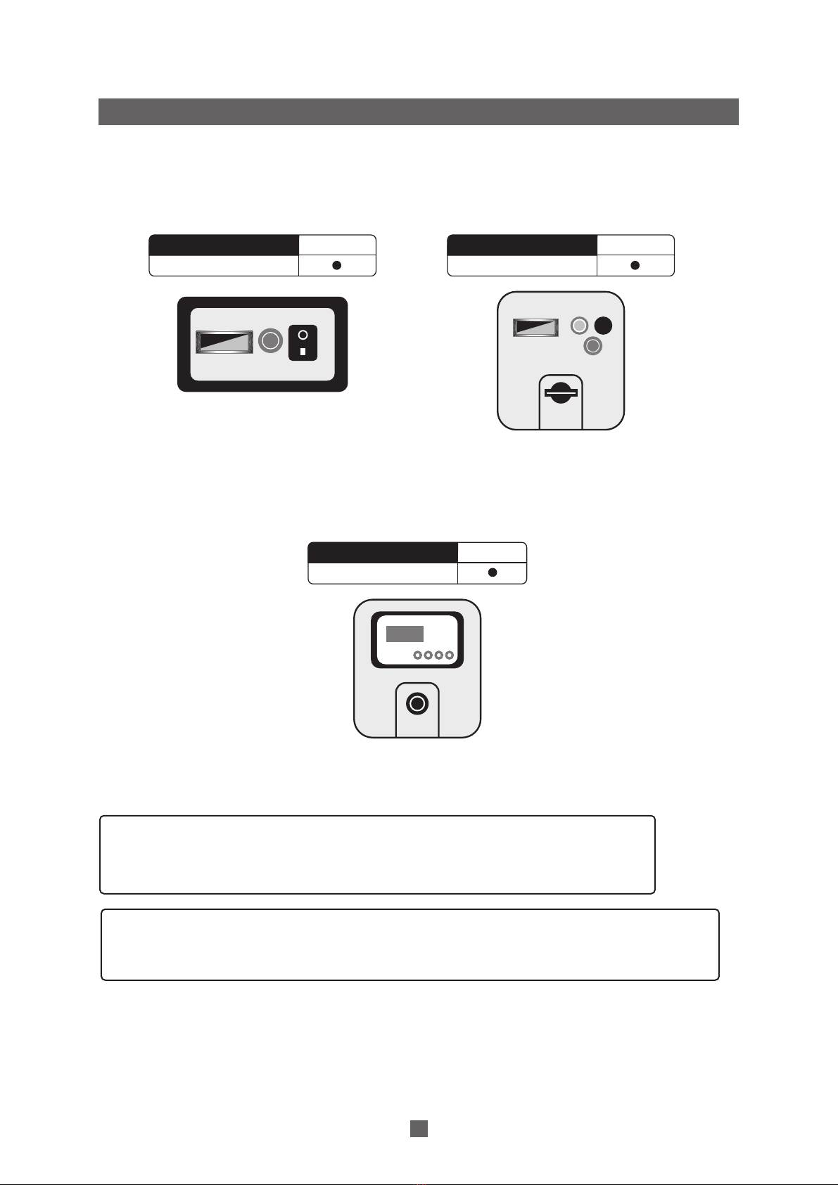
a) Dew point indicator: Located on the control panel, it displays the value of the pressure dew point.
b) Temperature switch: Located inside the dryer, this temperature switch is adjustable from 0 up to 35 °C.
c) Energy Saving Device: (ESD) This device helps dryer save energy when there is not any compressed air flow
in the dryer. (Please see the models have standart and optional in next page)
d) Filter change alarm on the front panel
3

** IMPORTANT NOTE: The Dryer has two Compressed Air Filter inside.
It is better to change filter element for the best efficiency when the alarm light is active.
It is recommended to keep replacement filter elements in your stock
in order to replace them when needed.
ATTENTION : Dryair DK range dryers have low pressure drop according its competitors.
Do not use Dryair DK range dryers together with other dryers which have higher
pressure drop without getting the confirmation from our technical team.
3.1. Operation
A) Control panels: The control panel of the dryer includes the following elements:
3. OPERATION
4
2
4
1
3
5
1) Dewpoint indicator (Standard)
2) Filter change Alarm**
3) Start / Stop Button 1) Dewpoint indicator (Standard)
2) Start Light
3) N/A
4) Filter change Alarm**
5) Main Switch
Dew point
indicator
1) ESD3 (Standard)
5) EMERGENCY STOP
ESD3
5
1
Dryair DK120 - Dryair DK130
Dryair DK140 - Dryair DK260
1 2 3
Monophase
Triphase
Monophase Dew point
indicator
Dryair DK10 - Dryair DK110

5
3) Follow the daily starting and shut down preocedure.
D) Daily starting and shut-down
1) Push on the green button to start the dryer.
2) The start light will indicate that the dryer is running.
3) To stop the dryer, first stop the airflow (either shut-down the air compressor or close the inlet/outlet or
by-pass valve) When the air flow is stopped set the rotary switch on 0 Set it again on I in order to keep the
preheating on.
4) IMPORTANT NOTE!
Avoid leaving the dryer stopped when compressed air is still flowing through it.
5) To switch the already preheated dryer on again, simply push the green start button.
2) IMPORTANT NOTE!
After a long stop of the dryer it is MANDATORY to allow a preheating period of minimum 4 hours
before starting again, to avoid any compressed air flow during preheating.
-
-
3.2. During Operation
Regularly check the digital temperature controller ESD3 or dewpoint indicator on dryer.
B) Start up and shut-down
Warning: Avoid leaving the dryer off when compressed air is still flowing through it.
C) Starting for the first time or after a long stop
1) Set the rotary switch to I This preheats the dryer and turns the drain system on.
It is recommended to leave the dryer power on permanently so the crankcase heater runs continuously.
E) Digital Temperature Control technical features (ESD3)
ESD3: PLC clear text multilingual indication of alarms, maintenance and running hours
+ Energy Saving Device automatic switching OFF at no load and ON when warm compressed air is entering.
(Please see the ESD3 manual which is given with Dryer)

Dryair DK
REFRIGERATED TYPE COMPRESSED AIR DRYERS
Technical Specifications
& Diagrams

Nominal Pressure
Maximum pressure
Maximum ambient temperature
Minimum ambient temperature
Maximum inlet temperature
FOR ALL MODELS
7 bar
16 bar
50
°
C
4
°
C
60
°
C
Capacity
(m3/h)
Connection
Size
Refrigerant
gas
Maximum
working
pressure
(bars)
Pressure drop
(mbar)
Voltage
Maximum
ambient
temperature
(
o
C)
Maximum
inlet
temperature
(
o
C)
Absorbed
Power
(kw)
Max.
Amperaje
(Amp)
Fuse
Amperaje
(Amp)
0,32
0,32
0,37
0,37
0,60
0,68
0,82
1,08
130
1,30
1,18
1,43
1,81
2,77
3,14
4,03
4,62
5,51
6,16
7,76
9,92
11,13
11,91
15
15
18,43
230/1/50
230/1/50
230/1/50
230/1/50
230/1/50
230/1/50
230/1/50
230/1/50
230/1/50
230/1/50
230/1/50
230/1/50
230/1/50
400/3/50
400/3/50
400/3/50
400/3/50
400/3/50
400/3/50
400/3/50
400/3/50
400/3/50
400/3/50
400/3/50
400/3/50
400/3/50
R134a
R134a
R134a
R134a
R134a
R134a
R134a
R134a
R134a
R134a
R134a
R134a
R134a
R134a
R134a
R134a
R134a
R134a
R134a
R134a
R134a
R134a
R134a
R134a
R134a
R134a
Dryair DK10
Dryair DK20
Dryair DK30
Dryair DK40
Dryair DK50
Dryair DK60
Dryair DK70
Dryair DK80
Dryair DK90
Dryair DK100
Dryair DK110
Dryair DK120
Dryair DK130
Dryair DK140
Dryair DK150
Dryair DK160
Dryair DK170
Dryair DK180
Dryair DK190
Dryair DK200
Dryair DK210
Dryair DK220
Dryair DK230
Dryair DK240
Dryair DK250
Dryair DK260
60
60
60
60
60
60
60
60
60
60
60
60
60
60
60
60
60
60
60
60
60
60
60
60
60
60
< 200
< 200
< 200
< 200
< 200
< 200
< 200
< 200
< 200
< 200
< 200
< 200
< 200
< 200
< 200
< 200
< 200
< 200
< 200
< 200
< 200
< 200
< 200
< 200
< 200
< 200
50
50
50
50
50
50
50
50
50
50
50
50
50
50
50
50
50
50
50
50
50
50
50
50
50
50
16
16
16
16
16
16
16
16
16
16
16
16
16
16
16
16
16
16
16
16
16
16
16
16
16
16
7
3
3
3,5
3,5
6
7
8,5
11,5
12,5
15
15,5
20
24
14,5
16
21
22,5
27
29,5
41,5
49
57,5
60,5
81,5
81,5
102
21
35
50
87
130
170
198
283
354
467
588
825
1100
1310
1628
2200
2620
3144
3696
4800
5522
6584
7434
8496
9912
11800
4. TECHNICAL SPECIFICATIONS
Model
1/2
1/2
1/2
3/4
3/4
3/4
1 1/2
1 1/2
1 1/2
2
2
2
2
3
3
3
3
DN100
DN100
DN100
DN100
DN150
DN150
DN150
DN200
DN200
4
4
4
4
8
8
10
16
16
16
16
25
25
16
20
25
25
30
30
50
50
63
63
100
100
125

2
34
567
8
AIR INLET
AIR OUTLET
S
9
AIR CIRCUIT:
-A: Air/Refrigerant exchanger
-B: Manual valve
-C: Solenoid valve and timer
-D: Air filter
A
BC
REFRIGERANT CIRCUIT:
-1. Compressor
-2. Fan
-3. Condenser
-4. Fan switch**
-5. High pressure switch*
-6. Filter dryer
-7. Expansion valve
-8. Air/Refrigerant exchanger
-9. Hot gas by-pass valve**
D
1
M
REFRIGERANT GAS FLOW
COMPRESSED AIR FLOW
DRAIN FLOW
IMPORTANT NOTICE:
5 : Only from
Dryair DK40
to
DK 90
*
9 : Only from
Dryair DK
70
to
DK 90
**
Dryair DK10-Dryair DK90
5.1 AIR FLOW DIAGRAMS
8
5. DIAGRAMS

2
34
578
9
AIR INLET
AIR OUTLET
S
REFRIGERANT GAS FLOW
COMPRESSED AIR FLOW
DRAIN FLOW
6
12
AIR CIRCUIT:
-A: Air/Refrigerant exchanger
-B: Manual valve
-C: Membrane valve
-D: Solenoid valve
-E: Timer*
-F: Air filter**
A
B
D
REFRIGERANT CIRCUIT:
-1. Compressor
-2. Fan
-3. Condenser
-4. Fan switch
-5. High pressure switch
-6. Liquit recevier
-7. Filter dryer
-8. Expansion valve
-9. Air/Refrigerant exchanger
-10. Low pressure switch
-11. Suction acumulator****
-12. Hot gas by-pass valve***
10
C
IMPORTANT NOTICE:
E : Timer is not used from Dryair DK 140 to Dryair DK 260 *
F : Only from Dryair DK 110 to Dryair DK 170 **
12 : Hot gas by-pass valve with solenoid
control only used from Dryair DK 200 to Dryair DK 260 ***
11 : Suction acumulator is not used Dryair DK 100 and Dryair DK 110 ****
F
11
E
1
M
Dryair DK100-Dryair DK260
9

5.2 ELECTRICAL DIAGRAMS
A14: Filter change buzzer
A20: Drain supply
A40-1: Start capacitor
K01: Compressor start relay
S01: On/off button
S10: Fan pressure switch
S16: Filter service contact
M01: Compressor motor
M10: Fan motor
P: Compressor motor overload protector
HP: indicates high pressure
FIELD INSTALLED
Dryair DK10 - Dryair DK30
Electrical Circuit
10

Dryair DK40 - Dryair DK80
Electrical Circuit
A14: Filter change buzzer
A20: Drain supply
A40-1: Start capacitor
K01: Compressor start relay
S01: On/off button
S10: Fan pressure switch
S12: High pressure safety switch
S16: Filter service contact
M01: Compressor motor
M10: Fan motor
P: Compressor motor overload protector
HP: indicates high pressure
11
FIELD INSTALLED

Dryair DK90
Electrical Circuit
A14: Filter change buzzer
A20: Drain supply
A31: Bleeder resistor
A40-1: Start capacitor
A40-2: Run capacitor
K01: Compressor start relay
S01: On/off button
S10: Fan pressure switch
S12: High pressure safety switch
S16: Filter service contact
M01: Compressor motor
M10: Fan motor
P: Compressor motor overload protector
HP: indicates high pressure
FIELD INSTALLED
12

Dryair DK100 - Dryair DK130
Electrical Circuit
FIELD INSTALLED
A14: Filter change buzzer
A15: Running lamp (Green)
A20: Drain supply
A31: Bleeder resistor
A40-1: Start capacitor
A40-2: Run capacitor
K01: Compressor start relay
A50: Fan motor capacitor
S01: On/off button
S10: Fan pressure switch
S12: High pressure safety switch
S16: Filter service contact
M01: Compressor motor
M10: Fan motor
P: Compressor motor
overload protector
HP: indicates high pressure
NOTE 1: COMPRESSOR MOTOR DRAWING CAN BE
TYPE 1 or TYPE 2 DEPENDING ON ASSEMBLED
COMPRESSOR MODEL
NOTE 2: A15 DOES NOT EXIST IN DRYAIR DK 100
13

Dryair DK140 - Dryair DK190
Electrical Control Circuit
A11 : Remote control running lamp (Green)
A13: Remote control stand-by lamp (Red)
A41: Remote control alarm contact
A20: Electronic timer
A21: Drain Test
B16: Computer / Communication connection (RS485)
B17: Dewpoint analog output (4-20mA/0-100C)
EMR4: Phase protection relay
F10 : Control circuit protection
F11 : Control circuit protection
K20 : Drain supply test relay
P1 : Overload protector of compressor
P10 : Overload protector of fan motor
PT1 : Inlet air temperature sensor (PT100)
PT2 : Heat exchanger temperature sensor (PT100)
PT3 : Low pressure line sensor (PT100)
PT4 : High pressure line sensor (PT100)
PT5 : Ambient temperature sensor (PT100)
PT6 : Condenser outlet temperature sensor (PT100)
S2 : Limit switch
S3 : Emergency button
S5 : Remote control start button
S7 : Remote control stop button
S8 : Remote control contact
S9 : Obstruction for manual on/off
S10 : Fan pressure switch
S12 : High pressure safety switch
S13 : Low pressure switch
S15 : Service contact
S16 : Filter service contact
S31 : Fan heat termal 1
S32 : Fan heat termal 2
HP : Indicates high pressure
LP : Indicates low pressure
TH : Indicates thermal
NOTE 1: S16 DOES NOT EXIST IN Dryair DK180 and Dryair DK190
NOTE 2: DRAIN SYSTEM CAN BE TYPE 1 or TYPE 2
Broken line cables are dependent on customer wish.
FIELD INSTALLED
14

Dryair DK140 - Dryair DK190
A01 : Control circuit transformer
A30 : Compressor chankaser heater
B15 : Control circuit supply
EMR4: Phase protection relay
F1,F2 : A01 Primary protection
F3, F4: A30 overload protection
M1 : Compressor motor
M10 : Fan motor 1
M11 : Fan motor 2
P1 : Overload protector of compressor
P10 : Overload protector of fan motor
Q1 : Compressor contactor
Q10 : Fan contactor
X1 : Main supply connection
terminal block
ELECTRICAL SPECIFICATIONS
COMPRESSOR
UN 400V/3/50
FAN MOTOR
UN 400V/3/50
Dryair DK 140 FLA 10 A 1.82 Kw
Dryair DK 150 FLA 11 A 2.19 Kw
Dryair DK 160 FLA 15 A 2.9 Kw
Dryair DK 170 FLA 10 A 3.49 Kw
Dryair DK 180 FLA 10 A 3.9 Kw
Dryair DK 190 FLA 10 A 4.57 Kw
Dryair DK 140 FLA 0.50 A 0.18 Kw
Dryair DK 150 FLA 0.50 A 0.18 Kw
Dryair DK 160 FLA 0.72 A 0.270 Kw
Dryair DK 170 FLA 0.72 A 0.270 Kw
Dryair DK 180 FLA 1.8 A 0.510 Kw
Dryair DK 190 FLA 1.82 A 0.510 Kw
SIZE IS AMPS-600 VAC
ELECTRICAL SUPPLY LINE
3 PHASE + PROTECTION EARTH
CABLE SIZE
Dryair DK140
Dryair DK150
Dryair DK160
Dryair DK170
Dryair DK180
Dryair DK190
4G2.5mm
4G2.5mm
4G4mm
4G4mm
4G4mm
4G4mm
MAXIMUM SET : 15%
FIELD INSTALLED
MAIN PROTECTION AND DISCONNECTING MEANS SHALL BE PROVIDED BY
THE INSTALLER OF RESIDUAL CURRENT AUTOMATIC CIRCUIT BREAKER
15
Electrical Power Circuit

Dryair DK200 - Dryair DK220
Electrical Control Circuit
NOTE 1: A25 AND P2 JUST EXIST IN Dryair DK220
NOTE 2: DRAIN SYSTEM CAN BE TYPE 1 or TYPE 2
Broken line cables are dependent on customer wish.
FIELD INSTALLED
A11 : Remote control running lamp (Green)
A13: Remote control stand-by lamp (Red)
A20: Electronic timer
A21: Drain Test
A41: Remote control alarm contact
B16: Computer / Communication connection (RS485)
B17: Dewpoint analog output (4-20mA/0-100C)
EMR4: Phase protection relay
F10 : Control circuit protection
F11 : Control circuit protection
K20 : Drain supply test relay
P1 : Overload protector of compressor
P2 : Compressor thermal protection
P10 : Overload protector of fan motor
PT1 : Inlet air temperature sensor (PT100)
PT2 : Heat exchanger temperature sensor (PT100)
PT3 : Low pressure line sensor (PT100)
PT4 : High pressure line sensor (PT100)
PT5 : Ambient temperature sensor (PT100)
PT6 : Condenser outlet temperature sensor (PT100)
S2 : Limit switch
S3 : Emergency button
S5 : Remote control start button
S7 : Remote control stop button
S8 : Remote control contact
S9 : Obstruction for manual on/off
S10 : Fan pressure switch
S12 : High pressure safety switch
S13 : Low pressure switch
S15 : Service contact
S16 : Filter service contact
S31 : Fan heat termal 1
S32 : Fan heat termal 2
Q1 : Compressor motor contactor
Q10: Fan motor contactor
V1 : By-pass valve
HP : Indicates high pressure
LP : Indicates low pressure
TH : Indicates thermal
16
This manual suits for next models
26
Table of contents