Fral FLIPPERDRY 300 User manual

FLIPPERDRY 300

2

3
1. AVVERTENZE DI SICUREZZA
•Il deumidificatore deve essere sempre collegato a prese di corrente provviste di collegamento di terra.
L’inosservanza di tale norma, come per tutti gli apparecchi elettrici, è causa di pericolo delle cui conse-
guenze il costruttore non si assume alcuna responsabilità.
•Lo smontaggio dell’apparecchio con l’uso di attrezzi deve essere effettuato esclusivamente da un tec-
nico qualificato.
•Quando l’apparecchio è collegato ad una presa deve essere mantenuto in posizione verticale e non
deve essere spostato violentemente. Eventuali fuoriuscite di acqua dalla tanica o dalla vaschetta pos-
sono andare in contatto con parti elettriche con ovvie conseguenze di pericolo. E’ pertanto indispensa-
bile disinserire la spina prima di spostare l’apparecchio e vuotarne la tanica prima di sollevarlo.
Nel caso si verifichi uno spandimento d’acqua in seguito a bruschi spostamenti, il deumidificatore deve
restare fermo in posizione verticale per almeno 8 ore prima di essere avviato.
Distanze da ostacoli. L’apparecchio aspira l’aria nella parte posteriore e la espelle attraverso la griglia
anteriore; pertanto il pannello posteriore,che porta il filtro dell’aria, deve essere mantenuto ad una
distanza di almeno 15 centimetri da pareti.
•Il deumidificatore non deveinoltre essere fatto funzionare in spazi angusti che non consentano la dif-
fusione nell’ambiente dell’aria che esce dalla griglia anteriore. E’ invece possibile accostare i pannelli
laterali alle pareti senza creare difficoltà al regolare funzionamento.
• L’apparecchio è costruito rispettando le più severe norme di sicurezza. Non si deve peraltro inserire
oggetti appuntiti (cacciaviti, ferri da maglia o similari) nella griglia o nell’ l’apertura che resta scoperta nel
pannello posteriore quando si estrae il filtro): ciò è pericoloso per le persone e può danneggiare l’appa-
recchio.
•Non lavare con acqua l’apparecchio. Per pulire L’apparecchio utilizzare uno straccio umido dopo aver
scollegato la spina dalla presa.
• Non coprire la griglia frontale con panni o altri oggetti l’apparecchio si danneggia e può creare pericolo.
MANUALE D’USO E MANUTENZIONE
INDICE
1 AVVERTENZE DI SICUREZZA pag. 3
2 NORME TECNICHE DI RIFERIMENTO pag 4
3 USO E MANUTENZIONE pag 4
4 COLLEGAMENTO AD UNA
TUBAZIONE DI SCARICO pag. 5
5 MANUTENZIONE PERIODICA pag. 6
6 DATI TECNICI pag. 6
7 SCHEMA ELETTRICO pag. 19
ITALIANO

4
2. NORME TECNICHE DI RIFERIMENTO
L’APPARECCHIO E’ CONFORME AI REQUISITI ESSENZIALI DELLE SEGUENTI DIRETTIVE EURO-
PEE: DIRETTIVA MACCHINE (D.P.R. n° 459 del 24 luglio 1996), SICUREZZA ELETTRICA PER APPA-
RECCHIATURE IN BASSA TENSIONE (Legge n°791 del 18 ottobre 1977 e successivo D. L. n° 626 del
25 novembre 1996), COMPATIBILITA’ ELETTROMAGNETICA -EMC- (D.L. n° 476 del 4 dicembre 1992
esuccessivo D.L. n° 615 del 12 novembre 1996).
La conformità è dichiarata con riferimento alle seguenti norme armonizzate CEI EN 60335-2-40, CEI EN
55014-1, CEI EN 55104-2, CEI-EN 61000-3-2, CEI-EN 61000-3-3.
3. USO E MANUTENZIONE
3.1 PANNELLO COMANDI
Il pannello comandi si trova sul cofano anteriore sopra la griglia di espulsione dell’aria.
Ha forma ellittica, vedi disegno, e porta quattro luci di segnalazione ela manopola di regolazione.
Sopra a ciascuna luce è posta una scritta che indica in forma sintetica il significato del-
l’accensione della spia. Procedendo da sinistra verso destra si vedono:
• Luce verde “FULL”: quando si accende tale luce l’apparecchio si arresta poichè il serbatoio di rac-
colta della condensa è pieno
• Luce rossa “POWER”: indica che la spina è inserita in una presa alimentata e quindi all’interno del-
l’apparecchio si ha tensione; si devono pertanto adottare le cautele del caso
• Luce rossa “RUNNING”: si accende quando l’umidostato richiede il funzionamento del deumidifica-
tore; se le luci “PAUSE” e “FULL” sono spente, il compressore, salvo inconvenienti, è in funzionamento
• Luce rossa “PAUSE”: indica che il compressore è in attesa di partire; ciò si verifica ad ogni avvia-
mento e successivamente durante lo sbrinamento che avviene ciclicamente; la pausa dura circa cin-
que minuti.
•La MANOPOLA DI REGOLAZIONE consente di variare il livello di umidità desiderato in ambiente. I
numeri riportati indicano il livello crecente di prestazioni richieste. Pertanto ad un numero più alto cor-
risponde un umidità relativarichiesta più bassa. I valori medi consigliati sono compresi tra il 3 ed il 5
corrispondenti a circa il 60% di umidità relativa.
L’indicazione “CONT” significa che l’apparecchio funzionerà sempre indipendentemente dall’umidità
relativa. L’indicazione “OFF” indica che il contatto dell’umidostato è sempre aperto e quindi l’appa-
recchio non funziona; si faccia attenzione che però le parti interne sono in tensione finchè non si dis-
inserisce la spina.

5
PRIMA MESSA IN FUNZIONE
Per poter essere messo in funzione l’apparecchio deve essere rimasto in posizione verticale corret-
ta per almeno due ore. L’inosservanza di questa norma può causare un danneggiamento irrepara-
bile del compressore.
Trascorso il tempo appena citato, è possibile collegare la spina del deumidificatore ad una presa di
corrente a 230 Volts monofase. Si dovrà accendere almeno il led rosso “tensione” il quale indica che
l’apparecchio è alimentato correttamente. Qualora il led “funzionamento” sia spento ruotare in senso
orario la manopola posta nel pannello comandi sotto i led fino all’accensione del led suddetto. Si
accenderà anche il led “pausa” e dopo circa 5 minuti il deumidificatore inizierà a deumidificare.
3.2. ESE L’APPARECCHIO NON SI AVVIA OPPURE
NON DEUMIDIFICA ?
• Per prima cosa accertarsi che la luce rossa “POWER” sia accesa. Ciò indica che l’apparecchio è ali-
mentato. In caso contrario verificare che la spina sia correttamente inserita nella presa e che que-
st’ultima sia effettivamente alimentata eventualmente inserendo un altro apparecchio. Se quanto
sopra è verificato e la luce suddetta è spenta portare l’apparecchio al rivenditore dove lo avete acqui-
stato.
• Verificare che la luce verde “FULL” sia spenta. Se ciò non fosse controllare il corretto inserimento
della tanica togliendola e inserendola nuovamente fino a sentire lo scatto del microinterruttore.
Ovviamente controllare che la tanica sia vuota e che la levadel galleggiante sia correttamente allog-
giata nella sua sede.
•Controllare che sia accesa la luce rossa “RUNNING” il che indica che l’umidostato richiede il funzio-
namento. Quando l’apparecchio viene avviato dopo una sosta dovuta al raggiungimento dell’umidità
prescelta o dopo che si è vuotata la tanica, se l’umidostato richiede il funzionamento,oltre alle due
luci rosse centrali si accende anche la luce rossa “PAUSE”: In questa situazione, che dura circa 5
minuti, funziona solo il ventilatore mentre il compressore rimane fermo. Questo ciclo si ripete ogni 45
minuti circa per consentire l’eventuale sbrinamento del serpentino (evaporatore). Qualora la luce di
pausa resti accesa per più di sei minuti portare il deumidificatore presso il rivenditore.
• Qualoral’apparecchio apparentemente funzioni correttamente (due luci rosse centrali accese) ma non
produca acqua, o ne produca molto poca, verificare che l’umidità relativa in ambiente non sia inferio-
re al 40-45 %. In caso contrario portare il deumidificatore al rivenditore.
4. COLLEGAMENTOAD UNA
TUBAZIONE DI SCARICO
L'apparecchio prevede la possibilità di essere collegato direttamente ad una tubazione di scarico fissa.
In ogni caso lo scarico avviene tramite la tanica che ha già previsto un attacco con portagomma per il
collegamento di un tubo di gomma. Questa soluzione consente di conservare il dispositivo di arresto per
troppo pieno il che costituisce una sicurezza in caso di otturazione del condotto di scarico. Qualora lo
scarico non funzioni l’apparecchio si arresta segnalando l’inconveniente tramite la spia.
Per poter effettuare il collegamento allo scarico è necessario forare il portagomma che si trova nella
ITALIANO

6
parte inferiore della tanica. E’ consigliabile eseguire il foro prima con una punta del diametro di tre o
quattro mm, facendo attenzione che il foro sia in centro al portagomma, e successivamente con una
punta del diametro di otto millimetri.
Per il collegamento impiegare tubo possibilmente di silicone del diametro interno di 14 mm.
Sul fondo dell’apparecchio, in corrispondenza del portagomma si trova il foro per l’uscita del tubo di sca-
rico.
5. MANUTENZIONE PERIODICA
PULIZIA DEL FILTRO
L’unica manutenzione da eseguire periodicamente è la pulizia del filtro che va eseguita con frequenza
variabile a seconda della polverosità dell’ambiente e della quantità di ore al giorno di effettivo funziona-
mento dell’apparecchio.
Orietativamente per un uso normale la pulizia è sufficiente una volta al mese. Per un impiego in ambien-
ti polverosi si può rendere necessaria una frequenza anche più che doppia.
La pulizia va effettuata ponendo il filtro sotto il getto d’acqua di un normale lavandino nel verso contra-
rio rispetto al flusso dell’aria: il pannello forato deve stare verso il basso in modo che l’acqua tenda a
spingere il filtro verso il pannello stesso.
Richiedete al rivenditore i filtri di ricambio.
UMIDITÀ CONDENSATA IN 24 ORE (Litri) NELLE DIVERSE CONDIZIONI AMBIENTALI
modello
FLIPPERDRY 300
5 7 7 10,5 10 15 19
20°C,60%U.R. 20°C,80%U.R. 25°C,60%U.R. 25°C,80%U.R. 27°C,65%U.R. 30°C,80%U.R. 32°C,90%U.R.
temperatura ed umidità relativa dell’ambiente in cui opera il deumidificatore
CARATTERISTICHE TECNICHE
modello
FLIPPERDRY 300
230/1/50 250 6-35 35-100 300 5,5 300 R134a 23 35x32x70
alimentazione
elettrica
V/n/Hz
potenza
assorbita
W(*)
campo
funzion.
temp. °C
campo
funzion.
U.R.%
portata
aria
mc/h
capacità
tanica
litri
volume
ambiente
(indic.) mc
refrigerante
ecologico
peso
avuoto
Kg
dimensioni
LxPxH
cm
* Potenza media assobita (tiene conto del ciclo di sbrinamento) in ambiente a 20°C, 60% U.R.
6. DATI TECNICI

7
USE AND MAINTENANCE
INSTRUCTION MANUAL
INDEX
1 SAFETY INSTRUCTIONS pag. 7
2 PERTINENT TECHNICAL NORMS pag 8
3 USE AND MAINTENANCE pag 8
4 CONNECTION TO A DRAIN PIPE pag. 9
5 PERIODICAL MAINTENANCE pag. 10
6 TECHNICAL DATA pag. 10
7 ELECTRIC DIAGRAM pag. 19
ENGLISH
1. SAFETY WARNINGS
•The machine must be always connected using earthed electrical plugs as required for all electrical
appliances; the Company declines any responsibility for any danger or damage whenever this norm is
not complied with.
•Any Intervention on the machine using any Instrument must be carried out only by a qualified techni-
cian.
•When the machine is connected with a power socket, It must be in vertical position and any rough move
must be avoided because it could cause some water to come into contact with electrical parts; it is the-
refore recommended to removethe plug from the socket before moving around the dehumidifier; if any
water may have been spread on the machine, following some rough handling of the same, then the
dehumidifier must be turned off and can be started up again only after 8 hours.
•Correct Distance: the dehumidifier draws in the air from the back and lets out through the front side gril-
le: therefore the back panel, which supports the air filter, must be kept at a minimum distance of 15 cm
from the wall.
•The dehumidifier, moreover, must not be set running in narrow areas, which do not allow a proper dif-
fusion in the room of the air coming out from the grille. It is, instead, allowed, to set the machine sides
near the walls.
•The machine has been designed and manufactured in compliance with the strictest safety rules.
Therefore, pointed instruments (screw drivers, wool needles or similar ones) are not to be inserted in the
grille or in the opening of the back panel when it is opened to remove the filter. 1
•The machine must not be cleaned using water. To clean the dehumidifier, it should be used a wet cloth.
Remember to disconnect the plug from the socket before.
•The front panel should not be used to lay over it clothe or other things: it could cause damages or dan-
gers.

8
2. PERTINENT TECHNICAL
NORMS AND REGULATIONS
-The Dehumidifier has been designed and manufactured in conformity to all following European Norms
and Regulations:
-MACHINES NORMS (D.P.R., NR. 459 - 24th July 1996)
-SECURITY REGULATIONS FOR LOW TENSION APPLIANCES
(Law n. 791 - 18th Oct. 1977 and subsequent Law D.L. n. 626 - 25th Nov. 1996);
-ELECTROMAGNETIC COMPATIBILITY (EMC) - Law D.L. n. 476 - 4th Dec. 1992 and subsequent
D.L. 615 - 12th Nov. 1996).
It is hereby certified that the dehumidifiers conform to the Regulations: CEI EN 60335-2-40, CEI EN
55014-1, CEI EN 55104-2, CEI EN 61000-3-2 and CEI EN 61000-3-3.
3.0 USE AND MAINTENANCE
3.1 Control Panel
The control panel is placed on top of front side of the dehumidifier,
just over the air outlet grille.
It has elliptic form, four display lights and a speed controlling knob.
Over each signalling light there are following scripts:
• Green light 'FULL' the machine will stop when this light is 'on' because water tank is full.
•Red Light 'POWER': machine plug is correctly inserted into power main line socket.
• Red Light 'RUNNING: when this line is 'on', it means that dehumidifier is running; in fact, if the light'
PAUSE' and 'FULL' are off, the compressor should be in function.
• Red light 'PAUSE' :means that the compressor is ready to start; this light will be on every time this
machine is started and after every defrosting operation which takes place periodically: the pause will
last 5 minutes.
•The Humidity Controlling Knob: it permits to change the degree of, relative humidity of the room; th4e
numbers mean the different performance required from the dehumidifier to obtain the desired humi-
dity level. Therefor, the higher is the number, the lower is the humidity: The humidity values advised
are obtained with speed set between 3 and 5 to which corresponds a 60% relative humidity.
• The indicator 'CONT.' (continuous): means that the dehumidifier will continue to function independently
from the relative humidity.
• The Indicator 'OFF', means that the humidostat is not activated and therefore the machine is not run-
ning: don't forget, however, that electric power is in the machine till its plug is not removed from the
socket of the electric main line.

9
3.2 FIRST STARTING OF MACHINE
First Setting into function
Before starting the dehumidifier, make sure that the machine has been standing in vertical position for
at-least 2 hours. If one fails to observe this procedure, an unrepearing damage may be caused to the
compressor. Then one can proceed and connect the dehumidifier plug to a 230 V - one phase power
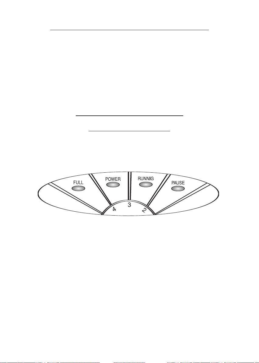
socket. The red light 'Power" will switch on confirming correct supply of power to the machine. If the light
'Functioning' is still off, turn clockwise the knob on the control panel till the light 'Functioning is 'On'. The
light 'Pause' will also switch on and, after 5 minutes the dehumidifier will start dehumidifying.
AND IF THE DEHUMIDIFIER DOES NOTSTART
OR DEHUMIDIFY ?
• First make sure that the red light' Power' is' On': this means that the current is fed to the machine. If
the power supply light is not on, make sure that the connecting wire plug may be properly inserted into
amain line socket in the room. After checking all this, if the power light is still off, then call the dealers
service.
• Make sure that the greeN light 'FULL' be off; If this is not the case, check the correct position of the
water tank in its seat by moving the tank until the microswith clicking in is heard. Before making this
control, you must obviously make sure that the tank be empty and that the float lever be in its seat.
• Make sure that the red light 'RUNNING' be 'on'; this means that the Humidostat activates the functio-
ning of the machine. When the dehumidifier is set again to functioning, after an idle period due to the
reaching of the preset humidity or after emptying the water tank, if the Humidostat requires functio-
ning of the machine, then beside the two red central lights, also the red light 'Pause' will light up.
• During this 5 minutes long phase, only the motor fan is running whereas the compressor is off. This
operating cycle takeplace every45 minutes to allow the defrosting of the cooler. When the red light
'Pause' will remain off for a period longer than 6 minutes, the dehumidifier should be brought to
Dealer's service centre.
•When the machine appears to be working correctly ( the twocentral red lights are on), but it is not pro-
ducing condensed water or produces only very little condensed water, it should be checked whether
the relativehumidity in the room maybe lower than 40.45%; if the relative humidity is higher than that,
the machine should be controlled by the dealers service.
4. CONNECTION TOADRAIN PIPE
the machine has the possibility to be connected with a fixed drain pipe to the water tank which is already
provided with a fitting with rubber hose holder. In this way the overflow stop continues to work as a safety
device in case the drain pipe may be clogged.
To connect the machine tank to the drain pipe, it is necessary to make a hole on the rubber hose hol-
der, which is placed in the lower side of the tank. It is advised to make the hole right in the centre of the
ENGLISH

10
rubber hose holder using first a 3-4 mm dia. drill and then an 8 mm dia. drill. For the connection, it should
possibly be used a silicon pipe having 14 mm internal diameter. On the bottom of the machine, just facing
the rubber hose holder there is a hole for the passage of the drain pipe
5. PERIODICAL MAINTENANCE
FILTER CLEANING
The only required periodical maintenance is the cleaning of the filter once every month, or more often
(even every two weeks) if the room is very dusty or the dehumidifier is working for many hours every day.
The cleaning must be done by placing the fitter under a water jet with the drilled panel facing the floor
so that the water jet may push the filter towards the drilled panel.
Note: You can require spare fitters from your dealer's service.
HUMIDITY CONDENSED IN 24 HOURS IN DIFFERENT CONDITIONS
model
FLIPPERDRY 300
5lit. 7 lit. 7 lit. 10,5 lit. 10 lit. 15 lit. 19 lit.
20°C,60%R.H. 20°C,80%R.H. 25°C,60%R.H. 25°C,80%R.H. 27°C,65%R.H. 30°C,80%R.H. 32°C,90%R.H.
in relation to the room temperature and r. humidity
model
FLIPPERDRY300
230/1/50 250 6-35 35-100 300 5,5 300 R134a 22 35x32x70
Power
supply
V/n/Hz
power
con-
sumption
W(*)
functioning
temperature
range °C
functioning
relative
humidity
range.%
air
volume
mc/h
Tank
capacity
litri
room
volume
(indic.) mc
ecological
refrigerant
Weight
Kg
size
LxPxH
cm
6. TECHNICAL DATA
note: The average power consumption has benn calculated in 20°C - 60% R.H.. room

11
MANUEL D’UTILISATION ET D’ENTRETIEN
INDEX
1 NOTICES DE SECURITE pag. 11
2 NORMES TECHNIQUES DE REFERENCE pag 12
3 UTILISATION ET ENTRETIEN pag 12
4 RACCORD A UNE CONDUITE DE VIDANGE pag. 13
5 ENTRETIEN PERIODIQUE pag. 14
6 DONNEES TECHNIQUES pag. 14
7 SCHEMA ELECTRIQUE pag. 19
FRANÇAISE
1. NOTICES DE SECURITE
•L’appareil doit toujours être branché à une prise de courant équipée dune prise de terre. La non obser-
vation de cette norme, valable pour tous les appareils eléctriques, peut causer des dangers dont le con-
structeur n’assume aucune résponsabilité.
• exclusivement par un technicien compétent.
•Lorsque l’appareil est branché à une prise il doit être maintenuen position verticale et ne doit pas être
déplacé violemment. Des écoulements d’eau événtuels du réservoir ou du bac peuvent créer des con-
tacts avec des parties eléctriques avec des conséquences évidentes de danger. Il est donc indispensa-
ble de débrancher la fiche avant de déplacer l’appareil et de vidanger le réservoir avant de le soulever.
Dans le cas d’une débordement d’eau à la suite de brusques dèplacements,le dèshumidificateur doit
rester ferme en position verticale au moins 8 heures avant de le mettre en marche.
Distances d’obstacles. le dèshumidificateur aspire l’air par l’arrière et la renvoie par la grille antérieure;
donc le tableau arrière, qui porte le filtre de l’air, doit être maintenu à une distance d’au moins 15 centi-
mètres des parois.
•L’appareil ne doit pas être mis en marche dans des endroits étroits qui ne permettent pas la diffusion
dans l’atmosphère de l’air qui sort de la grille antérieure. Par contee il est possibile d’encastrer les pan-
neaux latéraux contre les parois latérales sans créer des difficultés au fonctionnement regulier.
• L’appareil est réalisé en respectant les normes de sécurité les plus sèvères. On ne doit pas placer d’ob-
jets pointus (tournevis, aiguilles à tricoter ou similaires) dans la grille ou dans l’ouverture qui reste
découverte dans le
tableau arrière lorsqu’on enlèvele filtre): cela est dangereux pour les personnes et peut endommager
l’appareil.
•Ne pas laver l’appareil avec de l’eau. Pour nettoyer le dèshumidificateur utiliser un chiffon humide après
avoir débranché la fiche de la prise.
•Ne pas couvrir la grille antérieure avec des tissus ou d’autres objets car l’appareil peut s’endommager
et créer des dangers.

12
2. NORMES TECHNIQUES
DE REFERENCE
L’APPAREIL EST CONFORME AUX CONDITIONS REQUISES PAR LES DIRECTIVES EUROPEEN-
NES SUIVANTES: DIRECTIVE DES APPAREILS (D.P.R. n° 459 du 24 Juillet 1996), SECURITE ELEC-
TRIQUE POUR LES APPAREILLAGES A BASSE TENSION (Lois n° 791 du 18 Octobre 1977 et suc-
cessif D. L. n° 626 du 25 Novembre 1996), COMPATIBILITE ELECTROMAGNETIQUE - EMC - (D.L.
n°476 du 4 Décembre 1992 et successif D.L. n° 615 du 12 Novembre 1996).
La conformité est déclarée avec référence aux normes suivantes harmonisées CEI EN 60335-2-40, CEI
EN 55014-1, CEI EN 55104-2, CEI EN 61000-3-2, CEI EN 61000-3-3.
3. UTILISATION ET ENTRETIEN
3.1. DESCRIPTION DE L’APPAREIL
TABLEAUDE COMMANDES
Le tableau de commandes se trouve sur le capot antérieur au dessus de la grille d’évacuation d’air.
Il a une forme elliptique (voir dessin) ayant quatre zones de signalisation et la manette de réglage.
Au dessus de chaque zone une inscription indique synthétiquement le sens s’allumage du voyant. De
gauche à droite nous avons les zones suivantes:
•Zone verte “FULL” (plein): lorsque cette lumière s’allume,l’appareil s’arrête car le rèservoir qui récol-
te l’eau de condensation est plein
• Zone rouge “POWER” (tension): elle indique que la fiche est branchée dans une prise alimentée et
que par conséquent l’appareil est dans tension ; il faut donc adopter les précautions nécéssaires
• Zone rouge “RUNNING” (fonctionnement): s’allume lorsque l’humidistat commande le fonctionne-
ment du déshumidificateur; si les voyants “PAUSE” et “PLEIN” sont éteints, le compresseur, sauf
inconvénients, est en fonction
• Zone rouge “PAUSE” (pause): elle indique que le compresseur est en attente de démarrer; cela se
fait lors de la première mise en marche et succéssivement pendant le dégivrage qui se produit cycli-
quement; la pause a une durée de cinque minutes environ
•LA MANETTE DE REGLAGE permet de changer le niveau d’humidité désiré dans l’atmosphère. Les
indiqués indiquent le niveau croissant de performances demandé. Donc un numéro plus haut indique
une humidité relative plus basse. Les valeurs moyennes conseillées sont comprises entre le numéro
3 et le numéro 5 ce qui à environ 60% d’humidité relative. L’indication “CONT.” (en continu) signifie
que l’appareil fonctionne toujours indépendamment de l’humidité relative. L’indication “OFF” (eteint)
indique che le contact de l’humidostat est toujours ouvert et donc que l’appareil ne fonctionne pas;
attention que les parties à l’intérieur sont en tension jusqu’à ce que la fiche ne soit débranchée.

13
3.2. PREMIERE MISE EN ROUTE
Pour pouvoir mettre en fonction l’appareil, il doit rester en position verticale correcte pour 2 heures au
moins. La non obervance de cette règle peut causer un dommage irréparable du compresseur. Après 2
heures, il est possibile de brancher la fiche du dèshumidificateur à une prise de courant à 220 Volts
monophasé. Le led rouge de “power” (tension) doit s’allumer indiquant que l’appareil est corréctement
alimenté.Si le led de “running” (fonctionnement) reste éteint, tourner dans le sense des aiguilles d’une
montre la poignée placée sur le tableau des commandes sous les leds, jusqu’à ce led de fonctionne-
ment s’allume. Le led “pause” s’allumera en même temps et après environ 5 minutes l’appareil com-
mence à déshumidifier.
3.3 SI L’APPAREIL NE
DEMARRE PAS OU
S’IL NE DESHUMIDIFIE PAS?
Avant tout s’assurer que la lumière rouge “POWER” (tension) soit allumée. Cela significhe que l’appa-
reil est alimenté. Dans le cas contraire vérifier que la fiche soit coréctement branchée dans la prise et
que celle ci soit effectivement alimentée /essayer avec un autre appareil). Après ces contrôles et si la
lumière rouge ne s’allume pas, retourner l’appareil au détaillant ôu vous l’avez acheté.
•Vèrifier que la lumière verte “FULL” (pleine) soit éteinte. Dans le cas contraire contrôler que le réser-
voir soit bien placé, en le levant et en le remplaçant de nouveau jusqu’à entendre le déclenchement du
micro-intérrupteur. Contrôler que le réservoir soit vide et que le levier du flotteur soit corréctement placé
dans son logement.
Contrôler que la lumière rouge de “RUNNING” (fonctionnement) soit allumée: cela indique que l’humi-
dostat demande de fonctionner. Lorsque l’appareil a démarré, après un arrêt dû au fait d’avoir rejoint
l’humidité choisie ou après avoir vidangé le réservoir d’eau, di l’humidistat demande de fonctiionner, en
plus des deux lumières rouges centrales, la lumière “PAUSE” s’allume. Dans cette situation, d’une
durée d’environ 5 minutes, seul le ventilateur fonctionne alors que le compresseur est arrêté. Ce cycle
se reproduit chaque 45 minutes environ pour consentir le dégivrage éventuel du serpentin (évaporateur).
Si la lumière de “PAUSE” reste allumée pour plus de 6 minutes, retourner le déshumidificateur au reven-
deur.
•Si l’appareil fonctionne apparemment bien (deux lumières rouge centrales allumées) mais ne produit
pas de l’eau, ou très peu, vérifier que l’humidité relativedans l’atmosphère ne soit inférieur à 40-45%.
Dans le cas contraire,retourner le déshumidificateur au revendeur.
4. RACCORD A UNE CONDUITE DE VIDANGE
L’appareil prévoit la possibilité de raccorder l’appareil directement à une conduite de vidange fixe.
De toute façon la vidange se produit par l’entremise du bidon qui est déjà fourni d’un raccord porte-
caoutchouc pour raccorder un tube en caoutchouc. Cette solution permet de conserver le dispositif d’ar-
rêt du trop plein, qui est une sécurité dans le cas d’obturation du conduit de vidange. Si la vidange ne
fonctionne pas, l’appareil s’arrête en signalant l’inconvenient par l’entremise du voyant.
FRANÇAISE

14
Pour effectuer le raccordement à la vidage, il est nécessaire de percer le porte-caotchouc qui se trouve
dans la partie inférieure du bidon. Il est conseillé de faire d’abord un trou avec un forêt ayant une dia-
mètre de 3 ou 4 mm, le trou doit être fait au centre du porte-caoutchouc et ensuite avec un forêt de 8
mm de diamètre.
Pour le raccord utiliser un tube en silicone ayant un diamètre intérieur de 14 mm.
Un trout pour la sortie du tube de vidange est déjà prévu sur le fond de l’appareil.
5. ENTRETIEN PERIODIQUE
NETTOYAGE DU FILTRE
Le seul entretien à éffectuer périodiquement est le nettoyage du filtre qui doit être fait avec une fré-
quence variable selon la poussière dans l’atmosphère et selon le nombre d’heures de fonctionnement
effectif de l’appareil par jour.
Atitre indicatif pour une utilisation normale il est suffisant de nettoyer l’appareil une fois par mois.
Pour une utilisation plus lourde une fréquence de nettoyage double pourrait se rendre nécessaire.
Le nettoyage doit être effectué en plaçant le filtre sous un jet d’eau dans le sens contraire par rapport
au flux d’air: le tableau percé doit rester en bas afin que l’eau pousse le filtre vers le tableau.
Demander de filtres de rechanges au revendeur.
Umiditè condensée en 24 Heures (litres) en conditions atmosphèriques diverses
Modèle
FLIPPERDRY 300
5 7 7 10,5 10 15 179
20°C,60%H.R. 20°C,80%H.R. 25°C,60%H.R. 25°C,80%H.R. 27°C,65%H.R. 30°C,80%H.R. 32°C,90%H.R.
Température et humidité relative dans l’atmosphère oû le déshumidificateur fonctionne
CARACTERISTIQUES TECHNIQUES
Modèle
FLIPPERDRY300
230/1/50 250 6-35 35-100 300 5,5 300
R134a 22 35x32x70
Alimentation
Eléctrique
V/n/Hz
Puissance
absorbée
W(*)
Intervalle de
températ.
°C
intervalle.
U.R.
%
Débit
d’air
Cbm/h
Capacité
réservoir
litres
Volume
endroits
cbm
Gaz
réfrigérant
Poids
àvide
Kg
dimens.
LxPxH
cm
6. DONNEES TECHNIQUES
(*) Puissance moyenne absorbée (tient compte du cycle de dégivrage) à 20°C, 60% H. R.

15
BEDIENUNGSANLEITUNG UND WARTUNG
INHALT
1 SICHERHEITSHINWEIS pag. 15
2 TECHNISCHE NORMEN pag 16
3 INBETRIEBENAHME UND WARTUNG pag 16
4 ANSCHLUSS AN EIN ABFLUSSROHR pag. 18
5 PERIODISCHE WARTUNG pag. 18
6 TECHNISCHE DATEN pag. 18
7 SCHALTPLAN pag. 19
DEUTSCH
1. SICHERHEITSHINWEISE
Entfeuchter muß immer an Schutzkontakt-Steckdosen angesteckt werden. Die Nichtberücksichtigung
dieser Vorschrift, die ja alle elektrischen Geräte betrifft, ist gefährlich und schließt jegliche Verantwortung
der Firma aus.
Die Demontage mit Werkzeugen muß ausschfließlich durch qualifiziertes Personal erfolgen.
Wenn das Gerät angesteckt ist, muß es in vertikaler Position gehalten werden und nicht mit Gewalt ver-
schoben werden. Eventuelles, aus dem Kanister oder Behälter geflossenes Wasser, könnte mit elektri-
schen Teilen in Berührung kommen und somit gefährlich werden. Man muß also den Stecker herau-
snehmen, bevor man das Gerät verschiebt und den Kanister entleeren, bevor man es aufhebt. Sollte
beim Verschieben Wasser verschüttet werden, muß der Luftentfeuchter 8 Stunden in vertikaler Position
gehalten werden, bevor er wieder in Betrieb genommen werden kann.
Sicherheitsabstände. Entfeuchter saugt die Luft von hinten auf und läßt sie vorne, durch das Gitter
heraus; es muß also der hintere Deckel, der den Luftfilter enthält, mindestens 15 cm von der Wand ent-
fernt gehalten werden.
Das Gerät darf nicht in engen Räumen betätigt werden, wodas Zirkulieren der Luft, die vorne heraus-
strömt, nicht gewährleistet wird. Das Gerät kann aber seitlich neben Wänden gestellt werden, ohne
seine Funktion zu beeinträchtigen.
Entfeuchter wurde unter Berücksichtigung der strengsten Sicherheitsnormen hergestellt. Man darf
außerdem nicht spitze Gegenstände (Schraubenzieher, Stricknadeln usw.)durch das Gitter oder in die
Öffnung, die am hinteren Deckel freibleibt, wenn man den Filter entfernt, stecken: das ist für die
Personen gefährlich und kann außerdem das Gerät schädigen.
Das Gerät nicht mit Wasser reinigen. Zum Reinigen benützt man ein feuchtes Tuch, nachdem man den
Stecker herausgenommen hat.
Das Front-Gitter darf mit nichts zugedeckt werden, das schädigt das Gerät und könnte gefährlich wer-
den.
Den Filter regelmäßig reinigen: die Reinigung erfolgt durchschnittlich einmal im Monat; sollte das Gerät
in sehr staubigen Räumen betätigt werden, muß die Reinigung öfters erfolgen. Im Kapitel 5 ist die
Reinigung näher beschrieben. Wenn der Filter schmutzig ist, kommt wärmere Luft heraus als unter nor-
malen Bedingungen, das Gerät kann beschädigt und die Leistung beeinträchtigt werden.

16
2. TECHNISCHE NORMEN
Das Gerät entspricht den wesentlichen Anforderungen der folgenden europäischen Richtlinien:
Maschinenrichtlinien (D.P.R. n°459 vom 24 Juli 1996), Elektro-Sicherheitsschutz bei Geräten mit
Niederspannung (Gesetz n.791 vom 18. Oktober 1977 u. folgendes Gesetzesdekret n.626 vom 25
November 1996), Elektromagnetische Kompatibilität - EMC- (Gesetzesdekret n.476 vom 4. Dezember
1992 und fogendes n° 615 vom 12. November 1996).
Die Konformität ist durch Hinweis auf folgende Normen bestätigt: CEI EN 60335-2-40, CEI EN 55014-1,
CEI EN 55104-2, CEI EN 61000-3-2, CEI EN 61000-3-3.
3. INBETRIEBNAHME UND WARTUNG
3.1 SCHALTFELD
Das Schaltfeld befindet sich am vorderen Gehäuse, über dem Gitter, wo die Luft herauskommt, es ist
elipsenförmig , siehe Zeichnung, mit vier Kontrolleuchten und Regulierdrehknopf.
Über jeder Kontrolleuchte steht kurz ihre Bedeutung . Von links ausgehend hat man also:
Grünes Licht “FULL” (VOLL): schaltet dieses Licht ein, so kommt das Gerät zum Stillstand, da der
Kanister mit dem Kondensiationswasser voll ist.
Rotes Licht “POWER” (SPANNUNG): zeigt an, daß der Stecker angesteckt ist und das Gerät mit Strom
versorgt ist; es ist also Vorsicht geboten.
Rotes Licht “RUNNING” (BETRIEB) : es schaltet ein, wenn der Feuchtigkeitsmesser den Betrieb des
Luftentfeuchters verlangt; sind die Leuchten “PAUSE” und ”VOLL” ausgeschaltet, ist der Kompressor
in Betrieb.
Rotes Licht “PAUSE”:zeigt an daß der Kompressor bereit ist einzuschalten; das erfolgt bei jeder
Inbetriebnahme und nachher während des Abtauens,das zyklisch erfolgt; die Pause dauert etwa fünf
Minuten.
Mit dem Regulierdrehknopf reguliert man die gewünschte Feuchtigkeit im Raum. Je höher die Nummer
desto mehr wird die Luft entfeuchtet. Mit einer hohen Nummer wird also nach einer geringeren relativen
Luftfeuchtigkeit gefragt. Die Angabe “CONT.” (STÄNDIG) bedeutet, daß Entfeuchter, unabhängig von
der relativen Luftfeuchtigkeit, fortlaufend funktioniert. Die Angabe “OFF” bedeutet, daß der Kontakt
des Feuchtigkeitsmessers offen ist, und das Gerät somit nicht
funktioniert; Vorsicht aber, denn die inneren Teile sind in Spannung, solange der Stecker nicht herau-
sgezogen wird.

17
ERSTMALIGES EINSCHALTEN
Um eingeschalten werden zu können, muß das Gerät für mindestens zwei Stenden in korrekter, gera-
der Position gestanden haben. Die Nichtbeachtung dieser Regel könnte den Kompressor für immer
schädigen.
Nach Ablauf dieser Wartezeit, kann das Gerät an eine 220 Volt – Einphasen-Steckdose angeschlossen
werden. Es muß jetzt die rote Kontrolleuchte für “Spannnung” einschalten, die uns angibt, daß das Gerät
richtig versorgt wird. Sollte die Kontrolleuchte für “Betrieb” ausgeschaltet sein, dreht man , den sich im
Schaltfeld befindlichen Drehknopf, im Uhrzeigersinn, bis die Leuchte einschaltet. Auch die Leuchte für
“Pause” schaltet ein, und nach ungefähr fünf Minuten beginnt der Entfeuchter zu entfeuchten.
3.3 WAS TUN WENN DER ENTFEUCHTER
NICHT EINSCHALTET ODER
NICHT ENTFEUCHTET ?
Zuerst sollte man sich vergewissern, daß die rote Kontrollleuchte “SPANNUNG” eingeschaltet ist. Das
gibt uns an, daß das Gerät mit Strom versorgt ist, andernfalls kontrolliert man, ob der Stecker richtig
angesteckt ist und ob die Steckdose auch wirklich mit Strom versorgt ist ; eventuell durch Anstecken
eines anderen Geräts prüfen. Hat man dies alles nachgeprüft, und bleibt die oben genannte Leuchte
trotzdem ausgeschaltet, wendet man sich an den Verkäufer, der uns das Gerät verkauft hat.
Sich vergewissern, daß die grüne Kontrolleuchte “VOLL” aus ist. Ist das nicht der Fall, kontrolliert man,
ob der Kanister richtig festsitzt, eventuell herausnehmen und wieder einsetzen bis man das Klicken des
Mikro-Schalters wahrnimmt. Natürlich muß man dabei beachten, daß der Kanister leer ist und der Hebel
des Schwimmers auf seinem Platz ist.
Kontrollieren, ob die rote Kontrolleuchte “BETRIEB” eingeschaltet ist, was bedeutet, daß durch den
Feuchtigkeitsmesser die Inbetriebnahme gefordert wird. Schaltet das Gerät nach einer Pause, sei es
weil die gewünschte Luftfeuchtigkeit erreicht wurde oder weil man den Kanister entleert hat, wieder ein
weil vom Feuchtigkeitsmesser danach verlangt wird, leuchtet außer den zentralen roten Lichtern auch
das rote Licht für “PAUSE” auf: in dieser Situation, die ungefähr 5 Minuten dauert, funktioniert nur der
Ventilator, wobei der Kompressor stillsteht. Dieser Zyklus wiederholt sich etwa alle 45 Minuten, um even-
tuell das Abtauen der Serpentine (Evaporator) zu ermöglichen. Sollte das Licht “PAUSE” für mehr als 6
Minuten eingeschaltet bleiben, wendet man sich an den Verkäufer.
Sollte das Gerät funktionieren (die zwei mittleren roten Lichter sind eingeschaltet) aber kein Wasser oder
nur spärliches Wasser abgeben, kontrolliere man, ob die relative Raumluftfeuchtigkeit weniger als 40-
45% betrage. Andernfalls wende man sich an den Verkäufer.
DEUTSCH

18
4. ANSCHLUSS AN EIN ABFLUSSROHR
Entfeuchter kann direkt an ein fixes Abflußrohr angeschlossen werden. Jedenfalls erfolgt der Abfluß
durch den Kanister, der mit einem Anschluß für einen Gummischlauch und Halter versehen ist. Diese
Lösung ermöglicht die Aufbewahrung der Abstellvorrichtung für “ ZU VOLL” und damit hat man mehr
Sicherheit , falls der Abflußgang verstopft sein sollte. Sollte der Abluß nicht funktionieren, kommt das
Gerät zum Stillstand, was durch eine Kontrolleuchte angezeigt wird.
Zum Anschließen macht man in den Gummihalter, der sich am Kanister unten befindet, ein Loch. Es
wäre ratsam, das Loch zuerst mit einer 3-4 mm. –Spitze und dann mit einer 8 mm. -Spitze , genau in
der Mitte des Gummihalters zu bohren. Für den Anschluß benützt man möglichst einen Silikon-Schlauch
mit einem Innendiameter von 14 mm.
Unten am Gerät, dem Gummihalter gegenüber, befindet sich das Loch für den Ausgang des
Abflußschlauchs.
5. PERIODISCHE WARTUNG
REINIGUNG DES FILTERS
Die einzige periodisch auszuführende Wartung besteht in der Reinigung des Filters, die von der
Staubdichte des Raumes und vom zeitgemäßen wirklichen Funktionieren des Gerätes abhängt. Unter
normalen Bedingungen ist die Reinigung ungefähr einmal im Monat auszuführen.
In staubigen Räumen ist es manchmal sogar nötig zweimal oder auch mehrmals den Filter zu reinigen.
Für die Reinigung wird der Filter unter fließendem Wasser gehalten und zwar dem Luftstrom gegenüber
umgekehrt: der löchrige Teil muß unten sein, damit das Wasser den Filter gegen denselben stoßen kann.
Diese Filter können bei als Ersatzteile durchden Verkäufer nachgefragt werden.
Kondensierte Luftfeuchtigkeit in 24 Stunden (Liter) unter verschiedenen
Umweltbedingungen
Modell
FLIPPERDRY 300
5 7 7 10,5 10 15 19
20°C,60%R.F. 20°C,80%R.F. 25°C,60%R.F. 25°C,80%R.F. 27°C,65%R.F. 30°C,80%R.F. 32°C,90%R.F.
Temperatur und rel. Luftfeuchtigkeit im Raum wo Entfeuchter betaetigt wird
TECHNISCHE EIGENSCHAFTEN
Modell
FLIPPERDRY300
230/1/50 250 6-35 35-100 300 5,5 300
R134a 23 35x32x70
Stromver-
Sorgung
V/n/Hz
Absorbierte
Leistung
W(*)
Feld
Betrieb
Temp.
°C
Feld
Betrieb
Rel. L.
%
Luft
Cbm/h
Kapaz
Kani-
Ster
Raum-
Größe
(Indik.)
cbm
Ökologi-
sches
Kühlmittel
Leer
Gewicht
Kg
Ausmasse
LxUxH
cm
6. TECHNISCHE DATEN
(*) durchschnittlich absorbierte Leistung (berücksichtigt auch den Abtauzyklus) bei Raumtemp. 20°C, 60%R.F..

19
7. FLIPPERDRY 300

20
Table of contents
Languages:
Other Fral Dehumidifier manuals

Fral
Fral FDKA100.1 User manual

Fral
Fral DRC100 User manual

Fral
Fral FSW140 User manual

Fral
Fral FSW96 User manual

Fral
Fral FDNSRC44.1005 User manual

Fral
Fral FD980 User manual

Fral
Fral DD13C.ECO User manual

Fral
Fral FDNF62 Operating instructions

Fral
Fral DryDigit20 LCD User manual

Fral
Fral FSW100 Series User manual