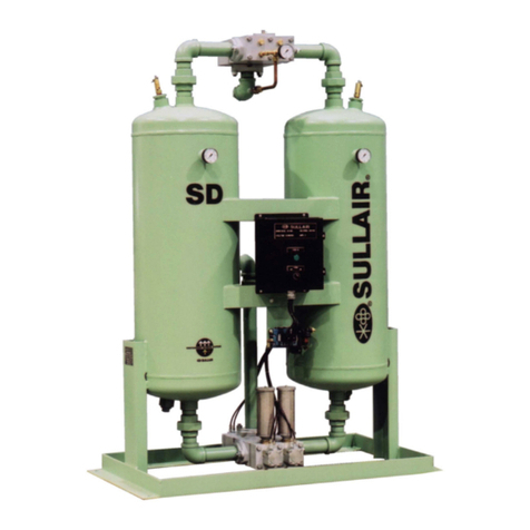
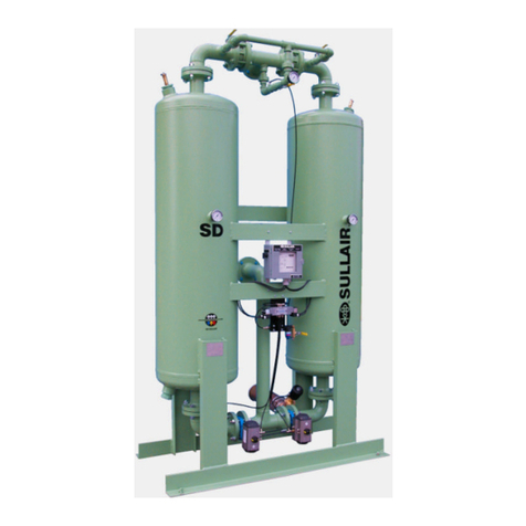
Sullair SD Series User manual

User Manual
SD Series
SD-220 to SD-600
3V OPTION
SD Heatless Desiccant
Compressed Air Dryer
Serial Numbers 0001 to 8795
Ref: 02250130-735

INSTALLATION, START-UP & MAINTENANCE MANUAL
SD-220 TO SD-600
REV 04 – 10 Oct 2003
Page 1 of 32
TABLE OF CONTENTS
SECTION 1: INTRODUCTION ....................................................................................... 4
1.1. GENERAL INFORMATION .................................................................................. 4
1.2. SAFETY INSTRUCTIONS.................................................................................... 4
1.2.1. Identification of Signs and Symbols in this Technical Manual ...................... 5
1.2.2. Safety Tips for Maintenance, Inspection and Assembly Work ...................... 5
1.3. PERSONNEL QUALIFICATION ........................................................................... 6
1.4. PRODUCT INFORMATION.................................................................................. 7
1.4.1. Pressure Vessel Regulations ........................................................................ 7
1.4.2. Airtightness test............................................................................................. 7
1.4.3. Overloading................................................................................................... 7
1.4.4. Technical Data Sheet.................................................................................... 8
1.4.5. Transport....................................................................................................... 9
1.4.6. Storage.......................................................................................................... 9
1.4.7. Use of a Pre and After Filter.......................................................................... 9
SECTION 2: INSTALLATION....................................................................................... 10
2.1. SET-UP AND INSTALLATION ........................................................................... 10
SECTION 3: START UP AND OPERATION ................................................................ 11
3.1. START UP/ SHUT DOWN.................................................................................. 11
3.2. DESCRIPTION OF THE OPERATION............................................................... 12
3.2.1. Description of the Operation ....................................................................... 12
3.2.2. Dryer Operating Sequence ........................................................................ 13
3.2.3. Electrical Control ......................................................................................... 14
SECTION 4: MAINTENANCE....................................................................................... 15
4.1. REPLACEMENT OF THE DESICCANT ............................................................. 16
4.2. DISPOSAL OF THE DESICCANT...................................................................... 16
4.3. CHANGING OF THE REGENERATION ORIFICE ............................................. 17
4.4. TECHNICAL DOCUMENTS ............................................................................... 18
4.5. FILTERS............................................................................................................. 20
4.5.1. General Comments and Use ....................................................................... 20
4.5.2. Function ...................................................................................................... 20
4.5.3. Assembly and Installation ........................................................................... 20
4.5.4. Maintenance................................................................................................ 20
4.5.5. Changing of Filter Elements........................................................................ 21
4.5.6. Accessories................................................................................................. 21

INSTALLATION, START-UP & MAINTENANCE MANUAL
SD-220 TO SD-600
REV 04 – 10 Oct 2003
Page 2 of 32
SECTION 5: DRYER FLOW CAPACITY AND PURGE ADJUSTMENT ...................... 22
5.1. DRYER FLOW CAPACITY................................................................................. 22
5.2. CORRECTION FACTOR FOR INLET TEMPERATURE .................................... 22
5.3. PURGE ADJUSTMENT...................................................................................... 23
SECTION 6: SPARE PARTS LISTS ............................................................................ 24
6.1. SPARE PARTS LIST FOR SD-220 TO SD-400 ................................................. 24
6.2. SPARE PARTS LIST FOR SD-500 & SD-600.................................................... 27
6.3. INLET & EXHAUST VALVE MANIFOLD ........................................................... 28
6.4. OUTLET CHECK VALVE MANIFOLD ................................................................ 29
SECTION 7: TROUBLE SHOOTING & FAULTS......................................................... 30
7.1. THE DEW POINT IS TOO HIGH........................................................................ 30
7.2. THE ADSORPTION DRYER DOES NOT SWITCH TOWERS .......................... 30
7.3. BACK PRESSURE IS TOO HIGH DURING REGENERATION PHASE............. 31
7.4. SHORT-TERM SHUT-DOWN ............................................................................ 31
7.5. SHUT-DOWN IN CASE OF A FAULT OR FOR MAINTENANCE ...................... 32
7.6. RE-STARTING ................................................................................................... 32

INSTALLATION, START-UP & MAINTENANCE MANUAL
SD-220 TO SD-600
REV 04 – 10 Oct 2003
Page 3 of 32
FOREWORD
This Sullair technical manual is intended to help you get to know the SD adsorption dryer
and to understand how to utilise its possibilities for application in accordance with its
intended use. Furthermore, this manual contains important information for safe, proper and
economic operation.
All instructions must be followed in written order to avoid danger to personnel and damage
to the dryer, which could result in downtime and/or premature wear and tear.
In addition to the technical manual and the accident prevention regulations which are valid
and compulsory in the country and in the particular workplace where the adsorption dryer
is being used, the recognized special rules for safe and proper working procedures are
also to be heeded. The technical manual must always be within reach wherever the
adsorption dryer is being used.
Each person involved with the set-up, start-up, operation, maintenance and repair of the
adsorption dryer in the User Company must have first read and understood the technical
manual and especially the safety tips.

INSTALLATION, START-UP & MAINTENANCE MANUAL
SD-220 TO SD-600
REV 04 – 10 Oct 2003
Page 4 of 32
SECTION 1: INTRODUCTION
1.1. GENERAL INFORMATION
The adsorption dryer of the SD-220 to SD-600 series is built according to the latest
technological developments and recognized safety rules. Its use however can endanger
life and limb of the user or of third parties, and can lead to considerable damage to the
adsorption dryer and other material assets if:
• it is operated by personnel not trained or instructed in its use,
• it is improperly used,
• it is improperly maintained or serviced.
This can result in the loss of all damage claims.
This adsorption dryer is designed for neutral media free of aggressive water, oil and solid
elements. Sullair accepts no liability for corrosion damage and malfunctions caused by
aggressive media.
Applications other than those mentioned in this manual must be agreed to by Sullair and
confirmed in writing.
In the interest of further development, Sullair
reserves the right to make changes at any
time, which, in keeping with the essential characteristics of the adsorption dryer described
here, may be necessary for increasing efficiency or for reasons relating to safety or to
normal business practice.
1.2. SAFETY INSTRUCTIONS
This technical manual contains basic tips, which must be followed during set-up, operation
and servicing. It is thus of utmost importance that it is read by the assembly technician
before installation and start-up as well as by the specialist or operator in charge, and it
must always be within reach at the location where the adsorption dryer is being used.

INSTALLATION, START-UP & MAINTENANCE MANUAL
SD-220 TO SD-600
REV 04 – 10 Oct 2003
Page 5 of 32
1.2.1. Identification of Signs and Symbols in this Technical Manual
The safety tips contained in this technical manual, whose disregard could endanger people
and property, are indicated by a general danger sign and the additional markings Danger!
or Attention!
Danger! / Caution!
Safety sign in accordance with DIN 4844 - W9
Warning against electrical voltage!
Safety sign in accordance with DIN 4844 - W8
Safety tips printed directly on the adsorption dryer must be heeded at all times and must
be kept completely legible.
☛Note
This sign refers to a procedure or sequence of particular interest or
importance. All tips must be followed to ensure proper use of this
adsorption dryer.
• This dot refers to working or operational steps. The steps are to be
carried out in the order of their appearance from top to bottom.
- The sign of a hyphen marks enumeration.
1.2.2. Safety Tips for Maintenance, Inspection and Assembly Work
The operator is to make sure that all maintenance, inspection, and assembly work is
carried out by special personnel who are authorized and qualified, and who are adequately
informed through careful study of the technical manual. For this reason, special attention
should be paid to the following attention and danger signs:

INSTALLATION, START-UP & MAINTENANCE MANUAL
SD-220 TO SD-600
REV 04 – 10 Oct 2003
Page 6 of 32
CAUTION!
• Never make structural changes to the adsorption dryer!
• Only use original Sullair spares and accessory parts!
• Never weld on a pressure vessel or change it in any way!
• Carry out maintenance work only when the adsorption dryer is
switched off, is depressurized and disconnected from the electric
power supply.
☛ Note
Refer to the desiccant material safety data sheet (MSDS) when installing or
disposing of desiccant.
DANGER!
Wear protective goggles when working with the desiccant!
☛ Note
• If desiccant comes into contact with the eyes, rinse eyes immediately with
a large amount of clear water.
• If the desiccant is spilled, clean up without causing swirls of dust.
• In case of fire, there is no restriction on the use of fire extinguishing
material; the reaction with water and foam is defined as strong.
• A mask must be worn to avoid inhalation of the desiccant dust.
1.3. PERSONNEL QUALIFICATION
The personnel involved in operation, maintenance, inspection and assembly must have the
corresponding qualifications to do this work. Areas of responsibility and supervision of the
personnel must be precisely established by the operator. Should the personnel not
possess the necessary knowledge, then they must be trained and instructed. If need be,
this training may be carried out by the manufacturer / supplier at the request of the
operator of the adsorption dryer. Further, the operator is to make sure that the personnel
completely understand the contents of the technical manual.

INSTALLATION, START-UP & MAINTENANCE MANUAL
SD-220 TO SD-600
REV 04 – 10 Oct 2003
Page 7 of 32
1.4. PRODUCT INFORMATION
The adsorption dryer is used for the purpose of drying compressed air and other gases
according to its respective design. As a "standard model" the adsorption dryer is equipped
with two desiccant vessels, a pre filter and an after filter, and depending on certain
conditions at the outlet, provides pure, dry and oil-free compressed air or gas.
1.4.1. Pressure Vessel Regulations
The pressure vessels are designed according to the standard technical requirements.
They fulfill the test of the certifying procedure and carry the “U”, “UM” ASME Symbol.
Range of application
Maximum Design Pressure 150 PSIG
Maximum Temperature
Minimum Temperature
500 °F
-20 °F
1.4.2. Leak test
Prior to shipment, all adsorption dryers are subjected to a comprehensive leak test
using compressed air.
1.4.3. Overloading
CAUTION!
Protect the adsorption dryer from overloading!
The adsorption dryer can become overloaded, if:
• The flow capacity of the medium to be dried increases,
• The temperature of the air at entry, and it’s corresponding humidity
increases,
• The minimum operating pressure decreases,
• The pre filtration and separation of impurities are not sufficient, or the
filter drain fails.

INSTALLATION, START-UP & MAINTENANCE MANUAL
SD-220 TO SD-600
REV 04 – 10 Oct 2003
Page 8 of 32
1.4.4. Technical Data Sheet
SD-220 SD-300 SD-400 SD-500 SD-600
Process medium Air, free of aggressive elements
Inlet/Outlet Connections (NPT) 1-1/2" 1-1/2" 1-1/2" 2” 2”
Flow capacity (1) (SCFM) 220 300 400 500 600
Desiccant Activated alumina
Qty of desiccant per Vessel [lbs] 126 167 220 272 350
Filter size (MPH / MPR) 300 300 420 470 700
Controls PLC Controller
Operating Voltage 120 Volts 60 Hertz 1 Phase (AC)
Drying Time per tower Standard: 5 minutes
With EDP Option: 2 minutes*
(1) At standard inlet conditions of 100oF, 100 psig, and providing a –40oF pressure dewpoint according to DIN ISO 7183.
☛ Note
All values given above assume a standard dryer with a standard scope of
supply and standard operating conditions as explained above. Dryers that
have been specifically modified for a particular application may have
different values than those shown.
* EDP (Enhanced Dew Point) Option indicates a dryer which has been
specifically set up at the factory to obtain a –100oF pressure dewpoint. This
option requires deration of the rated flow. Contact Sullair for details.

INSTALLATION, START-UP & MAINTENANCE MANUAL
SD-220 TO SD-600
REV 04 – 10 Oct 2003
Page 9 of 32
1.4.5. Transport
After the adsorption dryer has been delivered, it must be checked for damage that may
have occurred during transport. Any damages should be reported immediately to the
transport company to begin the claim process.
☛ Note
For lifting and transportation, only the skid of the dryer may be used.
Do NOT support the dryer by the interconnecting piping any other
attached component.
1.4.6. Storage
If the adsorption dryer is to be stored for a long period of time, its place of storage must be
dry and free of dust. There has to be a minimum ambient temperature of 33°F (+1°C).
1.4.7. Use of a Pre and After Filter
In order to prevent droplets of condensate, oil, or dirt from getting into the desiccant, a
Sullair MPH pre-filter must be installed up stream of the adsorption dryer. Without proper
pre-filtration an oil film will build up on the desiccant reducing it’s drying capacity and
degrading performance. In order to prevent a damage to downstream components by
activated alumina dust (caused by abrasion of the desiccant bed), a Sullair MPR after-filter
must be mounted immediately downstream of the adsorption dryer. Since no condensate
should accumulate in the after-filter, this filter is normally equipped with a manual valve.
Both filters are normally equipped with a differential pressure gauge as this provides an
indication of the degree of contamination of the filter elements, and when the elements
should be replaced.

INSTALLATION, START-UP & MAINTENANCE MANUAL
SD-220 TO SD-600
REV 04 – 10 Oct 2003
Page 10 of 32
SECTION 2: INSTALLATION
2.1. SET-UP AND INSTALLATION
Once at the installation location, the dryer must be positioned so that sides are easily
accessible. The piping is to be connected to the dryer at a slight upward slope. Isolation
valves are to be installed at the inlet and outlet and a by-pass line with an additional shut-
off valve should be mounted around the adsorption dryer. This is to ensure an
uninterrupted supply of compressed air in case of a problem with the dryer. Should the
installation site be subject to vibration, vibration dampers must be used to avoid
unnecessary vibration and abrasion of the desiccant bed.
Since the adsorption dryer has already been completely wired at our factory, the customer
only has to connect the power supply cable to the terminal strip according to the supplied
wiring diagrams.
☛ Note
Should you still have questions regarding installation, you can request
additional installation recommendations from Sullair.
CAUTION!
Do not hydrotest the dryer! All vessel assemblies are factory pressure
tested per design requirements prior to release from the manufacturer.
☛ Note
The dryer must be installed indoors in a heated environment (minimum
33°F) to ensure proper operation and warranty protection.

INSTALLATION, START-UP & MAINTENANCE MANUAL
SD-220 TO SD-600
REV 04 – 10 Oct 2003
Page 11 of 32
SECTION 3: START UP AND OPERATION
3.1. START UP/ SHUT DOWN
CAUTION!
All pipes and wire connections must be tightened!
Furthermore, before start-up:
• The pipes must be checked for the presence of scale, abraded material
from the threading, or other similar impurities.
• All shut off valves on the pre-filter, adsorption dryer, after-filter and on the
bypass line should be closed.
• The ambient temperature must not be less than 33°F
Breakdowns resulting from faulty installation do not fall under Sullair’s warranty obligation.
☛ Note
The following sequence is to be heeded for the initial start-up:
• Slowly open the inlet valve and gradually increase the pressure on the
chamber pressure gauge of the adsorption dryer. Do not open the valve
abruptly as the sudden pressure change may damage the dryer.
• Turn the switch to the "POWER ON" position.
• The adsorption dryer must be operated for approximately 3 to 4 hours
with the outlet valve closed. This is necessary in order to fully
regenerate the desiccant which will likely have been saturated during
transportation and installation.
• After the regeneration phase, open the shut off valve behind the after-
filter slowly while observing the chamber pressure gauge. Do not open
the valve abruptly as a sudden pressure change may damage the
dryer.
• The adsorption dryer is now ready for operation and will function
continuously and fully automatically.

INSTALLATION, START-UP & MAINTENANCE MANUAL
SD-220 TO SD-600
REV 04 – 10 Oct 2003
Page 12 of 32
3.2. DESCRIPTION OF OPERATION
The Sullair SD-220 to SD-600 adsorption dryer functions according to the pressure change
principle, using dry air regeneration. Two adsorption vessels filled with desiccant are
installed parallel to each other for this purpose. While the medium is being dried in one
vessel, regeneration takes place in the other vessel. The changeover from one vessel to
the other is performed in a fixed rhythm by means of a time-dependent control system. The
adsorption dryer operates continuously and fully automatically.
3.2.1. Description of the Operation
• The standard Sullair SD dryer operates on a 10 minute NEMA cycle. In this
configuration each desiccant chamber is drying for 5 minutes. This is known as a 5
minute half cycle. (EDP Dryers operate on a 4 minute NEMA cycle or 2 minute half
cycle).
• Wet air enters through the inlet switching valve and into the on line desiccant chamber
through the bottom. It is dried as it flows upward through the desiccant bed. Dry air
exits the dryer through the outlet check valve.
• At the outlet of each chamber, a portion of the dry air (purge air) is diverted to the
regenerating chamber. This dry air, expanded to near atmospheric pressure, will
remove previously adsorbed moisture as it flows downward through the desiccant bed
exiting through the purge exhaust mufflers.
• The purge air is controlled by a purge adjustment valve and purge orifices located in
the purge line. Purge pressure can be monitored on the purge pressure gauge. Refer
to section on purge adjustment for instructions on setting the purge rate.
• Near the end of each half cycle, the chamber being regenerated will be re-pressurized.
For this to occur, the exhaust valve of the chamber being regenerated closes while
purge air continues to flow. Re-pressurizing the regenerated chamber to operating
pressure before placing it into service minimizes fluidization of the desiccant and helps
prevent desiccant abrasion which causes desiccant dust to prematurely block pilot and
after-filter elements.
• Dryers operating at pressures greater than 120-125 PSIG or in an accelerated NEMA
cycle may be fitted with a re-pressurization valve. This valve assists the regenerated
chamber to reach dryer operating pressure before chamber switchover.
• Chamber switchover takes place when both towers are at full line pressure to minimize
desiccant movement.
• When switchover is complete, the regenerated tower will be placed into service and the
exhausted tower will depressurize and begin the regeneration cycle.

INSTALLATION, START-UP & MAINTENANCE MANUAL
SD-220 TO SD-600
REV 04 – 10 Oct 2003
Page 13 of 32
3.2.2. Dryer Operating Sequence
The Sullair SD-220-DDS to SD-600-DDS heatless air dryers use a PLC as the standard
controller. In the event of a power failure, the inlet valves remain in their position, and the
exhaust valves will close and dryer will pressurize both chambers. When power is
restored, the dryer will return to the same step in the cycle it was in before power was lost.
Energizing control panel: Power is turned ON – electrical circuit is energized.
When power is applied or restored to the control panel, the dryer will remain in a standby
state for one (1) minute period, allowing the dryer system to repressurize.
STEP 1 SELECT LEFT CHAMBER DRYING.
- De-energize solenoid EV-1R and EV-2L.
- Energize solenoid EV-1L and EV-2R.
- Inlet valve positioned for left chamber drying.
- Exhaust valve opened for right chamber regeneration.
- When regeneration time is complete, go to STEP 2
STEP 2 RIGHT CHAMBER REPRESSURIZATION.
- De-energize solenoid EV-1L and EV-2R.
- Inlet valves remain in open position.
- Right chamber exhaust valve closes.
- The repressurization timer starts a countdown of 45 sec.
- When repressurization time is complete, go to STEP 3
STEP 3 SELECT RIGHT CHAMBER DRYING.
- Energize solenoid EV-1R and EV-2L.
- Inlet valve positioned for right chamber drying.
- Exhaust valve opened for left chamber regeneration.
- When regeneration time is complete, go to STEP 4
STEP 4 LEFT CHAMBER REPRESSURIZATION
- De-energize solenoid EV-1R and EV-2L
- Inlet valves remain in open position.
- Left chamber exhaust valve closes.
- The repressurization timer starts a countdown of 45 sec.
- When repressurization time is complete, go to STEP 1
The dryer has completed one (1) full cycle and will repeat steps 1 through 4 until power is
disconnected from the control panel.

INSTALLATION, START-UP & MAINTENANCE MANUAL
SD-220 TO SD-600
REV 04 – 10 Oct 2003
Page 14 of 32
3.2.3. Electrical Control
DANGER!
Work on electrical installations may only be done by a specialist or by
other persons instructed in this type of work as long as they are under
the instruction and supervision of a specialist; the general rules for
working with electricity must be followed!
You will find the operating and control voltage on the data sheet.
The Sullair
SD-220 to SD-600 adsorption dryers are normally operated with a PLC
controller. The set times are adjusted at the factory during the test run.
CAUTION!
Do not change these adjustments!

INSTALLATION, START-UP & MAINTENANCE MANUAL
SD-220 TO SD-600
REV 04 – 10 Oct 2003
Page 15 of 32
SECTION 4: MAINTENANCE
☛ Note - In order to ensure continuous and trouble-free operation, a
maintenance contract with an authorized Sullair distributor is recommended.
The following points should be checked regularly:
Daily
• Carry out a general visual check and watch out for possible disruptions during
operation.
• Check function by manually operating the automatic condensate drain on the pre-
filter.
• Do an optical color test on the blue gel indicator:
Indicator Color Approx. dew point [ °C]
Blue gel
Blue
Pink
Transparent
- 25
0
+ 15
Weekly
• Check the differential pressure on the pre-filter, which should not exceed 10
PSID. Values greater than this indicate that the filter element must be changed.
• Check the differential pressure on the after-filter, which should not exceed 10
PSID. Values greater than this indicate that the filter element must be changed.
• Check the pressure of the regenerating vessel during regeneration after
depressurization. Any backpressure caused by blocked exhaust silencers will be
show here. Backpressure on the regenerating tower should not exceed 5 psig.
• Drain inlet and exhaust valve chambers using valves
provided below the valve (photo right).
• Drain pilot air filter housing of any condensate
(photo left).

INSTALLATION, START-UP & MAINTENANCE MANUAL
SD-220 TO SD-600
REV 04 – 10 Oct 2003
Page 16 of 32
Annually or after every 2500 hours of operation
• Check the desiccant for impurities and change it if necessary. A brown or yellow
color indicates that it has been contaminated with oil. Desiccant has an operating
lifetime of about 8000 hours under normal conditions.
• Check the screens installed in the desiccant chambers for impurities and if
necessary, clean them.
• Check the function of the inlet/exhaust valve combination by sending electrical
control signals.
• Replace the pilot air filter element.
4.1. REPLACEMENT OF THE DESICCANT
• Close dryer inlet/outlet isolation valves.
• Depressurize and switch off the adsorption dryer.
• Remove the drain plug and empty the old desiccant into a container.
• Screw the plug back in and fill new desiccant from above into the vessels.
• Pressurize the adsorption dryer per the start-up instructions and restore power to the
dryer.
NOTE: In order to ensure trouble-free operation, we recommend replacing the desiccant
at least every 8000 hours, or 2 years.
4.2. DISPOSAL OF THE DESICCANT
DANGER!
The desiccant can be disposed of at a suitable disposal site in
accordance with local or official regulations.
Note that the desiccant will remove and collect contaminants in the
process air and may therefore contain concentrated pollutants!

INSTALLATION, START-UP & MAINTENANCE MANUAL
SD-220 TO SD-600
REV 04 – 10 Oct 2003
Page 17 of 32
4.3. CHANGING THE REGENERATION ORIFICE
• Depressurize and disconnect power from the dryer.
• The regeneration orifice (Quantity = 2) are integrated into compression fittings that are
threaded directly into the top distribution block/check valve.
• Unscrew the tubing compression nuts on the orifice fittings, as well as the common
tubing.
• Remove regeneration orifice and re-install new orifice as required.
• Verify all tubing compression nuts are properly secured.
☛ Note
Consult Sullair
for recommendations and or replacement of the purge
regeneration orifice. Incorrect modification of the regeneration orifice can lead to
deterioration in performance of the dryer.
☛ Note
Use only original Sullair spare parts when working on the Sullair SD-220 to SD-
600 series dryers. The dryer type, model and serial number are required to
ensure correct parts are supplied. This information can be found on the
nameplate mounted on the control panel.

INSTALLATION, START-UP & MAINTENANCE MANUAL
SD-220 TO SD-600
REV 04 – 10 Oct 2003
Page 18 of 32
4.4. TECHNICAL DOCUMENTS
INLET – PURGE EXHAUST MANIFOLD
For SD-220 through SD-600

INSTALLATION, START-UP & MAINTENANCE MANUAL
SD-220 TO SD-600
REV 04 – 10 Oct 2003
Page 19 of 32
4.4 TECHNICAL DOCUMENTS (Continued)
OUTLET CHECK VALVE MANIFOLD
For SD-220through SD-600
Other manuals for SD Series
3
This manual suits for next models
5
Table of contents
Other Sullair Dehumidifier manuals

Sullair
Sullair SAR024 User manual

Sullair
Sullair SMC-3 User manual

Sullair
Sullair SD Series User manual

Sullair
Sullair SRC User manual

Sullair
Sullair DHL-80 User manual

Sullair
Sullair SD Series User manual

Sullair
Sullair RC Series Troubleshooting guide

Sullair
Sullair DBP Series Troubleshooting guide

Sullair
Sullair DHL-80 Troubleshooting guide

Sullair
Sullair SM1100 Installation and operating instructions