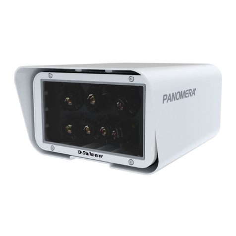
dallmeier PANOMERA S4 Guide

English
Commissioning
005110 / 2.0.0 / 2017-07-12
S4-S8

Informaon about Copyright, Trademarks, Design Patents
© 2017 Dallmeier electronic GmbH & Co.KG
The reproducon, distribuon and ulizaon of this document as well as the communicaon of its contents to others without express authorizaon is prohibited.
Oenders will be held liable for the payment of damages.
All rights reserved in the event of the grant of a patent, ulity model or design.
Figures in this document may dier from the actual product.
We reserve the right to make technical modicaons.
The manufacturer accepts no liability for damage to property or pecuniary damages arising due to minor defects of the product or documentaon, e.g. print or spelling errors, and for those not
caused by intenon or gross negligence of the manufacturer.
All trademarks idened by ® are registered trademarks of Dallmeier electronic.
All trademarks idened by *) are trademarks or registered trademarks of the following owners:
Google and Google Chrome of Google Inc. headquartered in Mountain View, California, USA;
JavaScript of Oracle Corporaon (and/or its aliates) headquartered in Redwood Shores, California, USA;
Microso, Internet Explorer, Microso Edge and Windows of Microso Corporaon headquartered in Redmond, Washington, USA;
Mozilla and Firefox of Mozilla Foundaon headquartered in Mountain View, California, USA;
NVIDIA and GeForce of NVIDIA Corporaon headquartered in Santa Clara, California, USA.
Third-party trademarks are named for informaon purposes only.
Dallmeier electronic respects the intellectual property of third pares and always aempts to ensure the complete idencaon of third-party trademarks and indicaon of the respecve holder of rights.
In case that protected rights are not indicated separately, this circumstance is no reason to assume that the respecve trademark is unprotected.

www.dallmeier.com 3
Commissioning S4-S8
Contents
1 Validity 4
2 Documents 4
2.1 This Document 4
2.2 Other Applicable Documents 5
3 Approvals/Cercaons 5
4 Typographical Convenons 6
5 Safety Instrucons 7
6 General Notes 9
6.1 Scope of Delivery 9
6.2 Transportaon and Packaging 9
6.3 Warranty 9
6.4 Appropriate Use 10
6.5 Operaon 10
6.6 Formaon of Condensaon 11
7 Requirements 12
7.1 Ambient Condions 12
7.2 Power Supply 13
8 Maintenance and Inspecon 14
9 Limits of the System 15
10 Installaon 16
10.1 Installaon on Wall Mount Bracket 17
10.2 Installaon on Ceiling Mount Bracket 18
11 Connecons 24
12 Conguraon 26
12.1 System Requirements 26
12.2 Conguraon Steps 28
12.3 Establishing the Connecon (Panomera® WebCong) 28
12.4 Login (Panomera® WebCong) 29
13 Technical Specicaons 30
14 Dimensions 31

4www.dallmeier.com
S4-S8 Commissioning
1 Validity
This document applies to the following Panomera® mulfocal sensor systems:
• Panomera® S4 – S8
Figures in this document may dier from the actual product.
2 Documents
The product documentaon contains several documents which are included in the scope of delivery in a printed form and/or on a digital medium.
Addional informaon, if available, is provided exclusively on the website www.dallmeier.com.
Read the available product documentaon carefully and thoroughly before using the respecve device or soware applicaon.
Always follow the contained instrucons, notes and warnings and observe the technical specicaons in the relevant product data sheet.
Keep all documents in legible condion and in a suitable locaon for future reference.
Regularly check the website www.dallmeier.com for the latest product documentaon updates.
2.1 This Document
Commissioning
The document entled “Commissioning” (this document) contains detailed informaon concerning the installaon, connecon and commissioning of the
above-menoned Panomera® mulfocal sensor systems as well as safety instrucons and general notes.
The target audience of this document is trained system integrators.

www.dallmeier.com 5
Commissioning S4-S8
2.2 Other Applicable Documents
Data Sheet
The product data sheet contains detailed technical specicaons, features and characteriscs of the respecve Panomera® mulfocal sensor system.
The target audience of the document is trained system integrators.
Installaon Requirements
The document entled “Installaon Requirements” contains the most important steps for installing and calibrang a Panomera® mulfocal sensor system.
The target audience of the document is trained system integrators.
Conguraon – Quick Guide
The document entled “Conguraon – Quick Guide” contains the most important steps for conguring a Panomera® mulfocal sensor system.
The target audience of the document is trained system integrators.
In this context, also read the documentaons of the following Dallmeier soware applicaons:
• PService3
• SMAVIA Recording Server
• SMAVIA Viewing Client
3 Approvals/Cercaons
The following approvals/cercaons were valid for the device at the me of this document’s compilaon:
• CE, FCC, ACA, DIN 50130-4 compliant
Visit www.dallmeier.com for possible updates.
Note (USA)
This equipment has been tested and found to comply with the limits for a Class A digital device, pursuant to Part 15 of the FCC Rules. These limits are designed to provide
reasonable protecon against harmful interference when the equipment is operated in a commercial environment. This equipment generates, uses, and can radiate radio
frequency energy and, if not installed and used in accordance with the instrucon manual, may cause harmful interference to radio communicaons. Operaon of this
equipment in a residenal area is likely to cause harmful interference in which case the user will be required to correct the interference at his own expense.

6www.dallmeier.com
S4-S8 Commissioning
4 Typographical Convenons
This document may contain various warning words and symbols that indicate potenal sources of danger:
DANGER
DANGER indicates a hazardous situaon which, if not avoided, will result in death or serious injury.
WARNING
WARNING indicates a hazardous situaon which, if not avoided, could result in death or serious injury.
CAUTION
CAUTION indicates a hazardous situaon which, if not avoided, could result in minor or moderate injury.
NOTICE
NOTICE indicates pracces for prevenng property damage, incorrect conguraons or faulty operaons.
For reasons of clarity and readability, various text formang elements and types of emphasis are used in this documentaon:
Instrucons are indicated by arrows (➡).
➡Always carry out instrucons one aer the other in the sequence described.
“Expressions” in quotaon marks generally indicate a control element on the device (switches or labels) or on its user interface (buons, menu items).
Paragraphs in italics provide informaon on basic principles, special features and ecient procedures as well as general recommendaons.

www.dallmeier.com 7
Commissioning S4-S8
5 Safety Instrucons
Only use the device if it is technically in proper working condion and for the intended purpose while keeping safety and potenal dangers in mind.
• Qualied Personnel
Assembly, installaon, connecon and commissioning of the device may only be carried out by qualied personnel.
This also applies to the maintenance, inspecon and repair of the device in complying with the regulaons of the DIN VDE 0701-0702 series of standards
(VDE 0701-0702: “Inspecon aer repair, modicaon of electrical appliances – Periodic inspecon on electrical appliances – General requirements for
electrical safety”).
• Regulaons
The use of video and audio surveillance systems is, in general, strictly regulated.
Inform yourself about the currently valid laws and regulaons regarding data, worker and environmental protecon before using the device and ensure
compliance with them.
• System Components
Only use internal components that have been tested and approved by Dallmeier.
Inappropriate internal components may cause malfuncons, damages and data loss and may result in the loss of warranty.
• Modicaons
Do not make any modicaons to the hardware or soware that have not been tested and approved by Dallmeier.
Inappropriate modicaons may cause malfuncons, damages and data loss and may result in the loss of warranty.
• Documentaon
The product documentaon contains several documents which are included in the scope of delivery in a printed form and/or on a digital medium.
Addional informaon, if available, is provided exclusively on the website www.dallmeier.com.
Read the available product documentaon carefully and thoroughly before using the respecve device or soware applicaon.
Always follow the contained instrucons, notes and warnings and observe the technical specicaons in the product data sheet.
Keep all documents in legible condion and in a suitable locaon for future reference.
Regularly check the website www.dallmeier.com for the latest product documentaon updates.
• Condensaon Water
If the device is brought from a cold to a warm environment, resulng condensaon water may cause malfuncons and damages.
In this case, wait (up to 8 hours) unl the device has reached room temperature before commissioning.

8www.dallmeier.com
S4-S8 Commissioning
• Earthing & Equipotenal Bonding
For the safety of persons (protecon against dangerous contact voltages) and devices (protecon against over-voltages) as well as for the immunity of in-
formaon and communicaon technology equipment to electromagnec interferences (EMI), all protecve measures, which are specied by the currently
valid DIN, VDE and ISO standards and which provide for a standard-compliant earthing and a correct equipotenal bonding of electrical and electronic
devices, are mandatory and must be fullled by all means.
• Lightning Storms
To avoid damage to the device by electrical surge during lightning storms, all protecve measures, which are specied by the currently valid DIN, VDE and
ISO standards and which provide for a standard-compliant lightning protecon equipotenal bonding, are mandatory and must be fullled by all means.
• Operang Condions
Unfavorable operang condions may shorten the life of the device and may cause malfuncons, damages and data loss and may result in the loss of warranty.
Observe the specicaons given in the technical data, the operang condion requirements and the maintenance instrucons.
• Foreign Bodies
If objects or liquids get into the device, immediately disconnect it from the power supply (pull out the power plug).
Contact the sales partner responsible for your area.
• Burnt Smell
If you noce burnt smell or a formaon of smoke coming from the device, immediately disconnect it from the power supply (pull out the power plug).
Contact the sales partner responsible for your area.
• Opening
The device may only be opened by qualied personnel for inspecon, maintenance and repair.
• Disposal
Do not dispose waste electrical and electronic equipment into the household trash.
Disconnect the device from the power supply.
Remove all connected devices.
Return the device to your respecve sales partner.

www.dallmeier.com 9
Commissioning S4-S8
6 General Notes
6.1 Scope of Delivery
Included in the standard scope of delivery is:
• Sunshield
• Adapter plate incl. xing screws
• Eye bolt DIN 580 + safety wire rope (according to BGI 810-3)
• Connecon cables (power, network) according to the ordered Panomera® variant
• Product documentaon (published in print and/or on DVD-ROM)
The scope of delivery may dier depending on the ordered equipment, device variant or country of desnaon.
The funconal range of the device depends on the ordered equipment or device variant and may dier from this document’s content.
Certain funcons and features may require the purchase of an addional license.
6.2 Transportaon and Packaging
Store the original packaging for later transportaon.
Dallmeier is not responsible for any damage resulng from unprofessional/improper transportaon.
The device should only be shipped in the original packaging.
If the original packaging is no longer available, ensure that the used packaging suciently protects the device against damage, moisture, heat and cold.
6.3 Warranty
The terms and condions valid at me the contract was signed shall apply.

10 www.dallmeier.com
S4-S8 Commissioning
6.4 Appropriate Use
The patented Panomera® mulfocal sensor system is a totally novel camera technology parcularly developed for the extensive video surveillance of large-
scale areas. With Panomera®, enormous distances and areas are displayed in a completely new resoluon quality – in real me and at high frame rates.
With Panomera®, a huge area can be surveilled from a single locaon – and the resoluon can almost be scaled without limits by combining mulple
Panomera® mulfocal sensor systems to one array.
The innovave lens and sensor concept of the Panomera® oers a unique overall view while simultaneously capturing the nest of details even for long dis-
tances. The result is a signicant reducon of infrastructural demands. In places where previously several megapixel cameras would have been required, now
only one Panomera® mulfocal sensor system is sucient.
Panomera® goes far beyond the convenonal Full HD 1080p standard and megapixel resoluon.
Due to the mulfocal sensor system, all areas of the enre surveillance scene are simultaneously displayed at maximum detail resoluon.
No maer which part of the surveillance zone an operator focuses at any me, Panomera® always captures the enre event.
Therefore, an incident can always be reconstructed later to be used as evidence in court, regardless of where it happened, and it is possible to recognize the
individuals involved.
Panomera® enables full overview with minimum wear and nearly no maintenance.
The mulfocal sensor system thus provides long service life and long-term investment protecon.
The Panomera® mulfocal sensor system is designed for both indoor and outdoor use.
The camera unit is supplied with 48 V DC. The integrated heater is separately supplied with 48 V DC or 24 V AC.
6.5 Operaon
Observe the following notes for the operaon of the device:
• If the device or the cables connected to the device are located near sources with strong radiaon, the video image may be distorted.
• The device is equipped with automac gain control (AGC). In low light condions the image may be altered (e.g. noise). However, this is not a malfuncon.
• The quality of the video image depends on the lighng condions and the used monitor.
• The accuracy of the automac white balance (AWB) algorithm depends on the used lighng. Mixed light (consisng of arcial light and daylight) may
cause color distorons (inaccurate color reproducon).
• Poor lighng can lead to an incorrect white balance.

www.dallmeier.com 11
Commissioning S4-S8
6.6 Formaon of Condensaon
Condensaon forms mainly due to temperature or pressure uctuaons.
If the device is transported between locaons with high temperature dierences, condensaon may form on the outside of the housing as well as inside the
device. In this case, wait unl the temperature of the device has slowly adapted to the ambient temperature prior to commissioning.
The device is equipped with a pressure equalizaon element.
Pressure equalizaon elements are used to prevent the formaon of condensaon in sealed enclosures, where humidity normally cannot escape to the outside.
The pressure equalizaon element built-in on the back of the device connuously equalizes the internal pressure to the ambient pressure. Thus, the temper-
ature and humidity dierence between the housing interior and the ambient air is balanced, and hence the formaon of condensaon is largely prevented.
Condensaon Inside the Housing
Despite the built-in pressure equalizaon element, a sudden drop in temperature (e.g. based on heavy showers or thunderstorms) can cause water vapor
(moisture) inside the housing, resulng in condensaon on the inner surface of the front glass.
In this case, acvate the integrated heater manually (via the WebCong user interface of the Panomera® master module) unl the inner surface of the front
glass is free from fog. However, note that the built-in heater cannot be acvated if the internal housing temperature has exceeded +60 °C (140 °F).
The integrated heater turns on automacally when the temperature drops
by 2 °C within 10 minutes (intelligent heang control).
Condensaon on the Outside of the Housing
Condensaon on the outside of the housing may form temporarily – usually in
the early morning when the humidity level is high, as the ambient air is warming
faster than the outer surface of the housing.
This results in condensaon or fog on the outer glass pane (like dew on the grass).
This phenomenon is due to physical reasons and, therefore, does not constute a
defect.
ⓐ
ⓐPressure equalization element

12 www.dallmeier.com
S4-S8 Commissioning
7 Requirements
7.1 Ambient Condions
The device is designed for both indoor and outdoor use.
However, note that unfavorable local condions may shorten the lifeme of the product and may cause malfuncons or damages.
➡Do not install/operate the device in places
• with a large amount of dust and dirt,
• with steam or oil vapors (e.g. kitchen),
• with direct sunlight,
• with strong heat emissions (e.g. radiator),
• with improper ambient temperatures,
• near sources with strong radiaon (e.g. radio transmiers, magnec elds),
• with corrosive surroundings (e.g. gases, salt water),
• with insucient air venlaon (e.g. closed cabinet).
Environmental Condions
Suitable installaon sites Indoor/Outdoor
Operang temperature −40 °C to +50 °C (minimum start-up temperature: −30 °C)
Heater On: < +10 °C
Heater O: > +10 °C
−40 °F to 122 °F (minimum start-up temperature: −22 °F)
Heater On: < 50 °F
Heater O: > 50 °F
Relave humidity 0 % – 90 % RH, non-condensing
IP rang IP66

www.dallmeier.com 13
Commissioning S4-S8
7.2 Power Supply
The camera unit is supplied with 48 V DC. The integrated heater is separately supplied with 48 V DC or 24 V AC.
Note that the camera unit and the built-in heater must each be supplied separately (observe the pin assignment on the product rang plate).
WARNING
Electric shock hazard
Risk of death or serious injury
➡Always disconnect the used power supply unit from the mains socket (pull out the power plug) before connecng or
disconnecng the device.
Over-voltage (electrical surge)
Risk of death or serious injury as well as damage to the device
➡To ensure the safety of persons (protecon against dangerous contact voltages) and to prevent damage to the device
caused by electrical surge, a standard-compliant earthing of the device is mandatory.
NOTICE
Damage to the device resulng from improper power supply
➡Always ensure the correct polarity when using a 48 V DC power supply unit (oponally available).
Electrical Data
Voltage supply Camera: 48 V DC
Heater: 48 V DC / 24 V AC
Power consumpon Camera: Max. 80 W (depending on the model, see the respecve current product data sheet on www.dallmeier.com)
Heater: Max. 60 W
Connecon Hirschmann CA 3 GS (mang connector: Hirschmann CA 3 LD)

14 www.dallmeier.com
S4-S8 Commissioning
8 Maintenance and Inspecon
Maintenance and inspecon of the device may only be carried out by qualied personnel on compliance with the regulaons of the DIN VDE 0701-0702
series of standards (VDE 0701-0702: “Inspecon aer repair, modicaon of electrical appliances – Periodic inspecon on electrical appliances –
General requirements for electrical safety”).
Cleaning
If it is necessary to clean the device, observe the following notes:
NOTICE
Damage to the surface of the housing and sunshield due to improper cleaning
➡Clean the Panomera® housing and sunshield only with a so, dry and anstac cloth.
• Do not use detergents.
• Do not use microber cleaning cloths, glasses cleaning cloths, abrasive paper towels or cloths with seams, buons,
plasc or metal parts.
Damage to the coated front glass due to improper cleaning
➡Clean the coated front glass of the Panomera® only with the cleaning components recommended by Dallmeier (special
glass cleaner and coon cleaning cloths).
• Do not use common glass cleaners or other detergents.
• Do not use microber cleaning cloths, glasses cleaning cloths, abrasive paper towels or cloths with seams, buons,
plasc or metal parts.
• Only use a small amount of the recommended detergent.
• Avoid excessive rubbing.
• Do not let residues of the detergent dry on the front glass as this may damage the coated surface.

www.dallmeier.com 15
Commissioning S4-S8
9 Limits of the System
Aer installaon, commissioning, alignment and focusing of the Panomera® mulfocal sensor system, a calibraon of the module transions is required.
Note that
• a Panomera® mulfocal sensor system is always designed for a specic installaon height and lt angle (see respecve data sheet).
Deviaons can lead to faulty module transions.
• a recalibraon of the module transions is required whenever the distance to stac objects within a scene is changed (e.g. when changing the installaon
height or camera inclinaon).
In this case, carry out a calibraon of the module transions using the PService3 add-on “Panomera® AutoCalibraon”.
For more informaon, refer to the related PService3 documentaon.
• prior to the calibraon of the module transions each camera module must be opmally focused.
For this, use the “Lens Control” dialog in the WebCong user interface of the respecve Panomera® camera module.
• the automac calibraon of the module transions is not possible for low-contrast scenes.
In this case, place an object with sucient contrast in the corresponding module area and restart the calibraon.
• areas with clearly dierenable scene content (clearly recognizable spaal, object and surface structures) are preferred for the automac calibraon of the
module transions.
• not all edge transions can be corrected due to physical and opcal properes, since objects with dierent distances to the background always have a dif-
ferent parallax oset.
• due to diurnal and seasonal humidity and temperature uctuaons and the resulng component movements or material stresses (e.g. of poles and brack-
ets), image changes may occur mainly in more distant scene areas (e.g. changes of image secon and edge transions).

16 www.dallmeier.com
S4-S8 Commissioning
10 Installaon
The installaon of the device may only be carried out by qualied personnel.
Two people working together are required to mount the device.
WARNING
Falling device or collapsing ceiling
Risk of death or serious injury
➡Observe the manufacturer’s instrucons about the maximum adequate carrying capacity of the supporng structure.
➡For the installaon of the wall/ceiling bracket, always use screws and anchors suitable for your wall/ceiling type.
➡Ensure that the device is adequately secured during installaon and operaon with the supplied safety wire rope
(length = 1 meter, carabiner with screw-lock on both ends) to prevent it from falling.
The supplied safety wire rope conforms to the standard BGI 810-3 (“Safety at Producons and Events – Loads Suspended
above Persons”) and is designed to secure loads up to 35 kg (77 lbs).
ⓐEye bolt DIN 580
for safety wire rope (BGI 810-3)
ⓐ

www.dallmeier.com 17
Commissioning S4-S8
The beveled edge of the adapter plate is
poinng backwards (in the direcon of the
housing backside).
10.1 Installaon on Wall Mount Bracket
➡Mount the Panomera® on the wall mount bracket as shown in the gure above.
ⓐAdapter plate (already mounted at the factory)
ⓑ4× Hexagon socket head cap screw DIN 912 (M5 × 16)
ⓒ4× Washer DIN 125 – A5.3
ⓐ
ⓒ
ⓑ

18 www.dallmeier.com
S4-S8 Commissioning
10.2 Installaon on Ceiling Mount Bracket
❶
➡Place the Panomera® with the top side of the sunshield facing downwards on a clean and stable surface
(put a so cloth or similar under the sunshield to avoid scratching its surface coang).
➡Unscrew the 4 hexagon socket head cap screws ⓐ and remove the adapter plate ⓑ.
ⓐ4× Hexagon socket head cap screw DIN 912 (M6 × 12)
ⓑAdapter plate
ⓑ
ⓐ

www.dallmeier.com 19
Commissioning S4-S8
❷
➡Carefully slide the Panomera® out of the sunshield.

20 www.dallmeier.com
S4-S8 Commissioning
❸
➡Turn the Panomera® so that the top of the housing is facing up again.
➡Unscrew the 8 hexagon socket head cap screws ⓐ and remove the 4 plascs rails ⓑ from the housing.
ⓐ
ⓑⓐ8× Hexagon socket head cap screw DIN 912 (M6 × 10)
ⓑ4× Plastic rail
Other manuals for PANOMERA S4
4
This manual suits for next models
1
Table of contents
Other dallmeier Security System manuals
Popular Security System manuals by other brands

PTI
PTI Falcon Installation and operation manual

COBHAM
COBHAM netlink user manual

VisionStat Plus
VisionStat Plus MA-BCKS-5.6 Installation & user manual

IntelliSense
IntelliSense FlexGuard-Plus FG-930 installation instructions

ADEMCO
ADEMCO VISTA-32FB Installation and setup guide

Honeywell
Honeywell L5200 Series Installation and setup guide