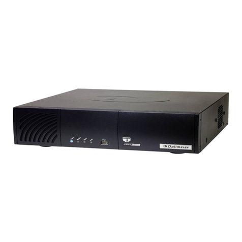
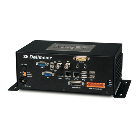
dallmeier DMS 2400 Guide

PRELOADED
English
Commissioning
003864 / Rev. 1.0.5 / 2014-03-13
Appliance
DMS 2400
DLS 1600

2 www.dallmeier.com
Contents
Validity .........................................................................................................................................................................................................................2
Safety Instructions....................................................................................................................................................................................................3
Requirements.............................................................................................................................................................................................................4
HDD Mounting...........................................................................................................................................................................................................5
Mounting.................................................................................................................................................................................................................... 6
Dimensions.................................................................................................................................................................................................................7
DMS 2400....................................................................................................................................................................................................................8
DLS 1600 ....................................................................................................................................................................................................................10
Commissioning and Local Login.......................................................................................................................................................................... 12
Commissioning and Remote Login..................................................................................................................................................................... 13
Indicators on the Front Side.................................................................................................................................................................................. 13
Validity
This documents applies to the SMAVIA appliance DMS 2400 and DLS 1600. It has been created in connection with version
8.1.3 and 8.6.3 of the software SMAVIA Recorder Server.
Conventions
This document may contain various warning words and symbols that indicate potential sources of danger.
DANGER
DANGER indicates a hazardous situation which, if not avoided, will result in death or
serious injury.
WARNING
WARNING indicates a hazardous situation which, if not avoided, could result in
death or serious injury.
CAUTION
CAUTION indicates a hazardous situation which, if not avoided, could result in minor
or moderate injury.
Notice
NOTICE indicates practices for preventing property damage, incorrect configurations
or faulty operations.
Instructions are indicated by arrows (Ø).
Expressions in bold/italics generally indicate a control element on the device (switches or labels) or on its user interface
(buttons, menu entries).
Paragraphs in italics provide information on basic principles, special features and efficient procedure as well as general
recommendations.
Contents

Only use the unit if it is technically in proper working condition and for the intended purpose while keeping safety and potential
dangers in mind.
Qualified Personnel
The installation, mounting, connection, commissioning and configuration of the unit may only be carried out by qualified
personnel. This also applies to the maintenance, testing and repair, whereat the regulations of the DIN VDE 0701 series of
standards (repair, modification and inspection of electrical appliances) must be followed.
Regulations
The use of video and audio surveillance systems is, in general, strictly regulated. Inform yourself about the currently valid
laws and regulations regarding data, worker and environmental protection before using the unit and ensure compliance with
them.
System Components
Only use internal components that have been tested and approved by Dallmeier. Inappropriate internal components can
cause malfunctions, damages and data loss and can result in the loss of warranty.
Modifications
Do not make any modifications to the hardware or software that has not been tested and approved by Dallmeier.
Inappropriate modifications can cause malfunctions, damages and data loss and can result in the loss of warranty.
Documentation
Read the documents included in the delivery carefully and thoroughly. Always observe the contained instructions, notes and
warnings.
Condensation Water
If the unit is brought from a cold to a warm environment, resulting condensation water can cause malfunctions and damages.
In this case, wait (up to 8 hours) until the unit has reached room temperature before commissioning.
Earthing & Equipotential Bonding
For the safety of persons (protection against dangerous contact voltages) and devices (protection against overvoltages) and
the immunity of information and communication technology equipment to electromagnetic interferences (EMI), all protec-
tive measures, which are specified by the currently valid DIN, VDE and ISO standards and which provide for a standard-com-
pliant earthing and a correct equipotential bonding of electrical and electronic devices, are mandatory and must be fulfilled
by all means.
Lightning Storms
To avoid damage to the unit by electrical surge during lightning storms, unplug the unit from the mains power supply (pull
out the power plug). This is also recommended, when the unit has been unused for a long period of time.
Operating Conditions
Unfavourable operating conditions can shorten the life of the unit and can cause malfunctions, damages and data loss and
can result in the loss of warranty. Observe the specifications given in the technical data, the operating condition requirements
and the maintenance instructions.
Shocks
Shocks can cause malfunctions and damages. The unit may not be moved while in operation.
Foreign Bodies
If objects or liquids get into the unit, immediately disconnect it from the power supply (pull out the power plug).
Contact the sales partner responsible for your area.
Burnt Smell
If you notice burnt smell or a formation of smoke coming from the unit, immediately disconnect it from the power supply
(pull out the power plug). Contact the sales partner responsible for your area.
Opening
The housing of the unit may only be opened by qualified personnel for commissioning, inspection, maintenance and repair.
Disposal
Do not dispose waste electrical and electronic equipment into the household trash. Disconnect the unit from the power sup-
ply. Remove all connected devices. Return the unit to your respective sales partner.
Safety Instructions
3
HDD Mounting Mounting
Safety Requirements DLS 1600 Local Login
Dimensions DMS 2400 Remote Login Indicators

Ambient conditions
The device is designed for stand-alone operation. As an option, it can be mounted and commissioned in a 19" standard rack.
General
Unfavourable ambient conditions can shorten the life and cause malfunctions or damages. Do not operate the device at
places with:
large scale dust and dirt
steam or oil vapours (e.g. kitchen)
unsuitable ambient temperatures
insufficient ventilation (e.g. closed cabinet)
direct sunlight
sources of strong heat dissipation (e.g. radiator)
sources of strong radiation (e.g. radio transmitter, magnetic field)
corrosive surrounding (e.g. gas, salt water)
Stand-alone operation
The device can usually be set up and operated at any place that meets the requirements above. In addition, observe the
following requirements and notes.
Computer room
This device is not designed for the use in a computer room as defined in the US fire protection regulation “Standard for
Protection of Electronic Computer/Data Processing Equipment, ANSI/NFPA 75”.
Secured room
Risk of manipulation and sabotage. A stand-alone installation should be operated in secured rooms with restricted access
only.
Socket-outlet
The used socket-outlet has to be installed near the device. It has to be easily accessible.
Operation in a 19" rack
The device can be installed and operated in a 19" standard rack, that is situated at a place that meets the requirements
above. In addition, observe the following requirements and notes.
Elevated ambient temperature
The ambient temperature in a multi-unit rack may be higher than the room ambient. Ensure that the maximum ambient
temperature in the rack complies with the requirements specified in the technical data.
Reduced air flow
The air flow in a (closed) rack may be reduced. Ensure that the amount of air flow required for a safe operation is not
compromised. Ensure sufficient ventilation with 4" (10 cm) of free space on the front, rear and right side of the device.
Earthing
Always ensure a reliable earthing of the device
Requirements
4 www.dallmeier.com

5
HDD Mounting
► Ensure that HDD drawer unit and housing are flush.
►Lock the HDD drawer unit with the key.
The HDD will be initialised and set into operation during the first
start of the device.
► Place the HDD drawer unit on the HDD’s underside.
► Ensure that the connections of the HDD are positioned
at the rear side of the HDD drawer unit.
►Ensure that HDD and HDD drawer unit flush at the rear
side.
► Mount the HDD drawer unit on the HDD with 4 screws.
►Unlock the HDD drawer unit with the key.
► Pull the HDD drawer unit carefully out of the housing.
► Remove the cover panel mounted on the HDD drawer unit.
► Insert the HDD drawer unit into the guide rail.
► Slide the HDD drawer unit carefully and completely into
the housing.
► Ensure that you slide it straight.
►Do not use any force.
Devices that have been ordered with hard disk drives can be mounted, connected and commissioned directly.
Devices that have been ordered without hard disk drives must be equipped with one 3.5" hard disk drive at least.
Note that all mounted hard disk drives
must be tested and released for mounting by Dallmeier (HDD whitelist in the Partner Forum)!
may not be formatted or partitioned!
Also note that the HDD slots 1 (front side, top) must be used in case only one hard disk drive is mounted:
Depending on the number and properties (capacity, new or used) of the mounted hard disk drives, various messages and
dialogues are displayed during the first start and the initialization.
► Confirm the messages, if required.
► Observe the instructions given in the dialogues.
► Note the appropriate Configuration documentation.
► Load the Default System Parameters as first step of the configuration.
IMPORTANT ADVICE
Notice
Ensure that the device is switched off and disconnected from
the power supply.
HDD Mounting Mounting
Safety Requirements DLS 1600 Local Login
Dimensions DMS 2400 Remote Login Indicators

Operation in 19" rack
► Exclusively use the 19" holder provided by Dallmeier.
► Insert the device into the 19" holder.
►Use the housing feet as guidance.
Mounting
► Use the 4 screws delivered with the 19" holder.
► Mount the housing in the 19" holder with the 4 screws.
► Ensure that the ventilation slots are not covered.
► Mount the device into the 19" rack.
► Observe the instructions of the rack manufacturer.
► Ensure 4 " (10cm) of free space at the front, rear and
right side.
► Connect the device as described on the following pages.
► Commission the device as described on the following
pages.
Stand-alone operation
► Ensure a stable and horizontal surface.
►Ensure 10 cm of free space at the front, rear and right side.
► Connect the recorder as described on the following pages.
► Commission the recorder as described on the following
pages.
6 www.dallmeier.com

7
Dimensions
445mm
133mm
425mm
133mm
95mm
38mm
427mm
431mm
424mm
HDD Mounting Mounting
Safety Requirements DLS 1600 Local Login
Dimensions DMS 2400 Remote Login Indicators

Connections
The number of the connections can differ depending on the ordered equipment or device variant. The following description
refers to a device with full equipment and optional connectors.
DMS 2400
8 www.dallmeier.com
Technical data
Dimensions W ×H ×D Approx. 16.7" × 4.8" × 17.6" (without feet) / 16.7" × 5.1" × 17.6" (with feet)
Voltage supply 115/230V AC +/– 10 %, 50 / 60 Hz
Power consumption Max. 145 W (operation without encoder board for analogue channels)
Max. 170 W (operation with 3 encoder boards for 24 analogue channels in total)
Heat power Max. 580 BTU/h
Ambient temperature + 5°C up to +40°C (41°F − 104°F), +20°C up to +25°C (68°F − 77°F) recommended
Humidity 5 – 70% RH, not condensing
Atmospheric load Dust-free
Weight Approx. 26 lbs (12 kg) with 2 HDDs
A Contact IN Cameras (1-6/7-12/13-18/19-24)
4× Weidmüller, 8 pins, only for switch / push button (dry contact)
M CVBS Interface
2× BNC, 75 Ohm, 1 Vpp, same signal as T2 (not active without T2)
B Serial Interface COM 3
2× Weidmüller 2 pins, 1× RS485 Full Duplex (optional)
N 3,5 mm Phone Jack
3×, not active
C Contact IN global (1-6)
Weidmüller, 8 pins, only for switch / push button (dry contact)
O Microphone IN
3,5 mm phone jack, red, 4,3 kOhm, 2,828 Vpp
D Mouse
PS/2, green
P Audio OUT
3,5 mm phone jack, green, 1 kOhm, 2,828 Vpp
E Keyboard
PS/2, violet
Q AUX / Line IN
3,5 mm phone jack, blue, 16 kOhm, 2,828 Vpp
F Relais OUT (1-5)
Weidmüller, 10 pins, max. 12V DC / 24V AC / 0.5A, 150mOhm
R Serial Interface COM 2
D-SUB, 9 pins, 1× RS232
G Video IN (1-16)
BNC, 75 Ohm, 1 Vpp, with loop-through, CVBS (optional)
S Video OUT DVI
Dual Link (24 + 5), DVI-D, 1920 ×1080 (not suitable for VGA adapter)
H Video OUT
Mini-D-SUB, 15-pole, 1920 × 1080
T1 SATA Interface
SATA OUT (optional, for DAS-4 Eco)
I Serial Interface COM 1
D-SUB, 9 pins, 1× RS232
T2 CVBS Interface
2× BNC, 75 Ohm, 1 Vpp (optional, for analogue monitors)
J Ethernet Interface 2
RJ45, 10/100/1000 Mbps (optional)
U Audio IN for analogue cameras (1-8/9-16)
D-SUB, 15-pole, 1 kOhm, 2,828 Vpp (for D-SUB/Cinch adapter cable)
K Ethernet Interface 1
RJ45, 10/100/1000 Mbps
V 12 V DC OUT
ODU socket, 2-pole, 12 V DC (for DAS-4 Eco)
L USB Interface
7× USB 2.0, type A
W Mains Connection
IEC C14 socket, 115/230V AC ±10%, 50/60 Hz
X Mains Switch
A B C D E F G H I J K L M N O P Q R S T1 T2 U V W X
Serial interface (B)
2×Weidmüller, 2 pins
Pin Assignment
1RS485 / TX+
2RS485 / TX-
12 3 4 5 6 7 8
1 2 3 4 5 6 7 8 9 10
2
1
1 2 4
3
Pin Assignment
3 RS485 / RX+
4 RS485 / RX-
9
DMS 2400
Assignment of the sockets
Relay OUT (F)
Weidmüller, 10 pins
Contact IN global (C)
Weidmüller, 8 pins
Contact IN cameras (A)
Weidmüller, 8 pins
Pin Assignment
1 GND
2 Contact 1
3 Contact 2
Pin Assignment
4 Contact 3
5 Contact 4
6 Contact 5
Pin Assignment Triggering event Type
1 + 2 Relay 1 Recorder in alarm state Normally open
3 + 4 Relay 2 None Normally open
5 + 6 Relay 3 System error Normally closed
7 + 8 Relay 4 None Normally open
9 + 10 Relay 5 More than 80% of the
secure tracks occupied
Schließer
12V DC OUT (U)
ODU socket, 2 pol
Pin Assignment
112V DC
2 GND
Pin Assignment
7 Contact 6
8 GND
Pin Assignment
1 GND
2 Contact 1
3 Contact 2
Pin Assignment
4 Contact 3
5 Contact 4
6 Contact 5
Pin Assignment
7 Contact 6
8 GND
Pin Assignment
1 Audio 1
2 Audio 2
3 Audio 3
4 Audio 4
5 Audio 5
Pin Assignment
6 Audio 6
7 Audio 7
8 Audio 8
9 GND 1
10 GND 2
Pin Assignment
11 GND 3
12 GND 4
13 GND 5
14 GND 6
15 GND 7 + 8
Audio IN (T)
D-SUB, 15-polig, ohne D-SUB/Cinch Adapterkabel
Serial interface (I and R)
D-SUB, 9 pins
Pin Assignment
1 DCD (Data Carrier Detect)
2 RxD (Receive Data)
3TxD (Transmit Data)
Pin Assignment
4DTR (Data Terminal Ready)
5 GND
6 DSR (Data Set Ready)
Pin Assignment
7RTS (Request to Send)
8CTS (Clear to Send)
9RI(Ring Indicator)
1 2 3 4 5 6 7 8
6
15
4
3
2
9
8
7
15
10
8
3
1
2
45
67
9
11 12
13 14
HDD Mounting Mounting
Safety Requirements DLS 1600 Local Login
Dimensions DMS 2400 Remote Login Indicators

DLS 1600
Connections
The number of the connections can differ depending on the ordered equipment or device variant. The following description
refers to a device with full equipment and optional connectors.
10 www.dallmeier.com
Technical data
Dimensions W ×H ×D Approx. 16.7" × 4.8" × 17.6" (without feet) / 16.7" × 5.1" × 17.6" (with feet)
Voltage supply 115/230V AC +/– 10 %, 50 / 60 Hz
Power consumption Max. 80W
Heat power Max. 273 BTU/h
Ambient temperatur 41°F − 104°F (+5°C bis zu +40°C), 68°F − 77°F (+20°C bis zu +25°C) recommended
Humidity 5 – 70% RH, non-condensing
Atmospheric load Dust-free
Weight Approx. 26 lbs (12 kg) with 2 HDDs
A Contact IN cameras (1-6/7-12/13-16)
3× Weidmüller, 8 pins, only for switch / push button (dry contact)
K Audio OUT
3,5 mm phone jack, green, 1 kOhm, 2,828 Vpp
B Serial Interface COM 1
2× Weidmüller, 2 pins, 1× RS485 Full Duplex (optional)
L Microphone IN
3,5 mm phone jack, red, 4,3 kOhm, 2,828 Vpp
C Contact IN global (1-6)
Weidmüller, 8 pins, only for switch / push button (dry contact)
M Video OUT (1-2)
BNC, 75 Ohm, 1 Vpp, CVBS (video only, no configuration)
D Relais OUT (1-5)
Weidmüller, 10 pins, max. 12V DC / 24V AC / 0.5A, 150mOhm
N Serial Interface COM 2
D-SUB, 9 Pins, 1× RS232
E Video IN (1-16)
BNC, 75 Ohm, 1 Vpp, with loop-through, CVBS
O SATA interface
SATA OUT (optional, for DAS-4 Eco, not in connection with DVD-RW
drive)
F Video OUT
Mini-D-SUB, 15 pole, 1280 x 1024 (video and configuration)
P Serial Interface COM 3
D-SUB, 9 Pins, 1× RS232
G Ethernet Interface 1
RJ45, 10/100/1000 Mbps
Q Audio IN (1-8/9-16)
D-SUB, 15 pole, 1 kOhm, 2,828 Vpp (for D-SUB / Cinch adapter cable)
H Ethernet Interface 2
RJ45, 10/100/1000 Mbps (optional)
R 12 V DC OUT
ODU socket, 2-pole, 12 V DC (for DAS-4 Eco)
I USB Interface
2× USB 2.0, type A
S Mains Connection
IEC C14 socket, 115/230 V AC ±10%, 50/60 Hz
J AUX / Line IN
3,5 mm phone jack, blue, 16 kOhm, 2,828 Vpp
T Mains Switch
A B C D E F G H I J K L M N O P Q R S T

DLS 1600
11
Assignment of the sockets
Relais OUT (D)
Weidmüller, 10 pins
Kontakt IN global (C)
Weidmüller, 8 pins
Contact IN cameras (A)
Weidmüller, 8 pins
Pin Assignment
1 GND
2 Contact 1
3 Contact 2
Pin Assignment
4 Contact 3
5 Contact 4
6 Contact 5
Pin Assignment Auslösendes Ereignis Type
1 + 2 Relay 1 Recorder in alarm state Normally open
3 + 4 Relay 2 None Normally open
5 + 6 Relay 3 System error Normally closed
7 + 8 Relay 4 None Normally open
9 + 10 Relay 5 More than 80% of the
secure tracks occupied
Normally open
Pin Assignment
7 Contact 6
8 GND
Pin Assignment
1 GND
2 Contact 1
3 Contact 2
Pin Assignment
4 Contact 3
5 Contact 4
6 Contact 5
Pin Assignment
7 Contact 6
8 GND
Pin Assignment
1 Audio 1
2 Audio 2
3 Audio 3
4 Audio 4
5 Audio 5
Pin Assignment
6 Audio 6
7 Audio 7
8 Audio 8
9 GND 1
10 GND 2
Pin Assignment
11 GND 3
12 GND 4
13 GND 5
14 GND 6
15 GND 7 + 8
Audio IN (Q)
D-SUB, 15 pol, without D-SUB/Cinch adapter cable
Serial interface(N)
D-SUB, 9 pins
Pin Assignment
1 DCD (Data Carrier Detect)
2 RxD (Receive Data)
3TxD (Transmit Data)
Pin Assignment
4DTR (Data Terminal Ready)
5 GND
6 DSR (Data Set Ready)
Pin Assignment
7RTS (Request to Send)
8CTS (Clear to Send)
9RI(Ring Indicator) 6
15
4
3
2
9
8
7
15
10
8
3
1
2
45
67
9
11 12
13 14
1 2 3 4 5 6 7 8
1 2 3 4 5 6 7 8
1 2 3 4 5 6 7 8 9 10
Serial interface (B)
2×Weidmüller, 2 pins
Pin Assignment
1RS485 / TX+
2RS485 / TX-
2
1
1 2 4
3
Pin Assignment
3 RS485 / RX+
4 RS485 / RX-
12V DC OUT (R)
ODU socket, 2 pol
Pin Assignment
112V DC
2 GND
HDD Mounting Mounting
Safety Requirements DLS 1600 Local Login
Dimensions DMS 2400 Remote Login Indicators

Commissioning and Local Login
12 www.dallmeier.com
►Observe the appropriate Operation and Configuration documentations.
Commissioning
► Connect the device and relevant peripherals to the voltage supply.
► Ensure that a monitor and a mouse are connected.
► Switch on the monitor, the peripherals and the device.
The user interface is displayed in the initial state after the start is complete.
In the initial state cameras are displayed with wildcards on the user interface.
Login
In the initial state it is possible to login without a password. The rights of the Administrator group are valid.
Note that the definition of the passwords and of the network parameters are necessary for remote access
(SMAVIA Viewing Client).
►Drag the mouse pointer to the lower screen edge.
The task bar with the LOGIN button is displayed.
► Click the LOGIN button.
The Recorder login dialogue is displayed.
► Click Later to login without changing a password.
The configuration interface is displayed.

Commissioning and Remote Login
13
Commissioning
►Connect the device to the network.
►Connect the device and relevant peripherals to the voltage supply.
►Switch on the peripherals and the device.
The device is available for remote configuration via Ethernet after the start is complete (up to approx. 5 minutes).
The IP address of the device (default 192.168.2.230) can be changed without login using the software PService or IP-Finder.
►Observe the appropriate Configuration documentation.
►Enter 192.168.2.230 as IP address (Host).
►Click the Connect button.
The connection will be established.
Device information is displayed.
The password input field is displayed.
Login
In the initial state it is possible to login remote using the serial number as password. The rights of the Administrator group
are valid.
Note that the definition of the passwords and of the network parameters are necessary for remote access
(SMAVIA Viewing Client).
►Observe the NetConfig documentation Installation and Commissioning.
►Start the software NetConfig.
►Enter the serial number (e.g. DAX2-12345678) as Password.
►Confirm with Login.
The configuration interface is displayed.
The configuration interface is compressed for slow network connections before transmission if the Slow Network check-box is
activated.
HDD Mounting Mounting
Safety Requirements DLS 1600 Local Login
Dimensions DMS 2400 Remote Login Indicators

14 www.dallmeier.com
Indicators on the Front Side
A Air filter
Behind the flap
B Power (blue)
Always lights up while the device is switched on.
C Record (green)
Indicates the recording activity (hard disk activity) of the device.
D Alarm (orange)
Indicates the alarm status of the device.
E Error (red)
Indicated failures, e.g. camera failures or hard disk faults.
F USB interface
USB 2.0, type A
G HDD, DVD-RW drives
Behind the flap
H Display
Shows information and status messages.
Indicators
Information and status messages are output with a display and status LEDs on the front side of the device. Air filter and
drives (HDD, DVD-RW) can be accessed conveniently with the integrated flaps.
A B C D E F G H
I J K L M N
I Serial number
J Internal temperature
K Model
L Version number SMAVIA Recording Server
M External temperature
N Line for status messages

15
Notes
HDD Mounting Mounting
Safety Requirements DLS 1600 Local Login
Dimensions DMS 2400 Remote Login Indicators

Information about Copyright, Trademarks, Design Patents
© 2014 Dallmeier electronic
The reproduction, distribution and utilization of this document as well as the communication of its contents to
others without express authorization is prohibited. Offenders will be held liable for the payment of damages. All
rights reserved in the event of the grant of a patent, utility model or design.
Wereservetherighttomaketechnicalmodications.
The manufacturer accepts no liability for damage to property or pecuniary damages arising due to minor de-
fects of the product or documentation, e.g. print or spelling errors, and for those not caused by intention or
gross negligence of the manufacturer.
Dallmeier electronic GmbH & Co.KG
Cranachweg 1
93051 Regensburg
Germany
www.dallmeier.com
info@dallmeier.com
Alltrademarksidentiedby®areregisteredtrademarksofDallmeierelectronic.
Other manuals for DMS 2400
1
This manual suits for next models
1
Table of contents
Other dallmeier Server manuals

dallmeier
dallmeier SMAVIA IPS 10000 User manual

dallmeier
dallmeier VideoNetBox User manual

dallmeier
dallmeier PVS IV Operating and maintenance instructions

dallmeier
dallmeier SMAVIA DMS 2400 II User manual

dallmeier
dallmeier SMAVIA VideoNetBox III Assembly instructions

dallmeier
dallmeier VideoNetBox Assembly instructions

dallmeier
dallmeier SMAVIA appliance VideoNetBox II Guide

dallmeier
dallmeier DIS-4/M SRS Guide

dallmeier
dallmeier IPS 2400 User manual

dallmeier
dallmeier DIS-2/M UTP Guide