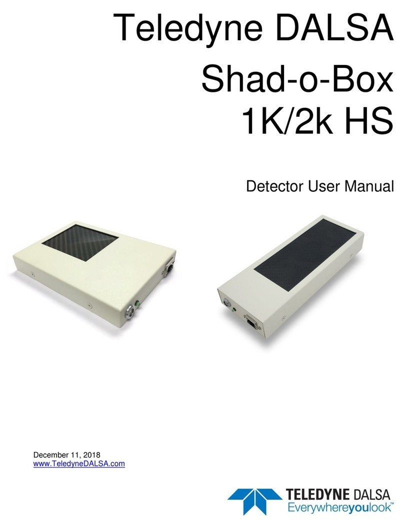
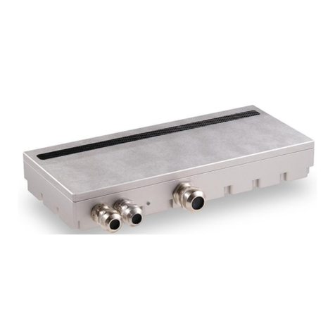
Dalsa Shad-o-Scan 3001 User manual

Shad-o-Scan User Manual, Rev04 2
Shad-o-Scan 3001/4501 X-Ray Detector Teledyne DALSA
© 2022 Teledyne DALSA. All information provided in this manual is believed to be accurate and
reliable. No responsibility is assumed by Teledyne DALSA for its use. Teledyne DALSA reserves the
right to make changes to this information without notice. Reproduction of this manual in whole or in
part, by any means, is prohibited without prior permission having been obtained from Teledyne
DALSA.
About Teledyne DALSA
Teledyne DALSA is an international high performance semiconductor and electronics company that
designs, develops, manufactures, and markets digital imaging products and solutions, in addition to
providing semiconductor products and services. Teledyne DALSA’s core competencies are in
specialized integrated circuit and electronics technology, software, and highly engineered
semiconductor wafer processing. Products and services include image sensor components; electronic
digital cameras; X-ray detectors; vision processors; image processing software; and semiconductor
wafer foundry services for use in MEMS, high-voltage semiconductors, image sensors and mixed-
signal CMOS circuits.
Contact Information
Please feel free to contact the global Teledyne DALSA sales office for ordering, to
obtain more detailed information or in case you encounter any problem operating the
detector:
Teledyne DALSA –Rad-icon Imaging
765 Sycamore Drive
Milpitas, CA 95035
USA
Tel: +1 408 736 6000
Fax: +1 408 736 6001
E-mail: sales.rad-icon@teledyne.com
Website: http://www.teledynedalsa.com/ndt

Shad-o-Scan User Manual, Rev04 3
Shad-o-Scan 3001/4501 X-Ray Detector Teledyne DALSA
Contents
System Precautions and Safety ____________________________________5
Safety Information .............................................................................................5
Labels................................................................................................................6
Symbols.............................................................................................................7
General safety instructions................................................................................8
EMC compliance ...............................................................................................8
System precautions...........................................................................................8
Regulatory Compliance.....................................................................................9
Detector Maintenance .......................................................................................9
Open Source Software Licenses.......................................................................10
Recycling...........................................................................................................10
The Shad-o-Scan Detector________________________________________12
Detector Highlights...................................................................................................12
Setting up the Detector___________________________________________13
Detector Connectors and Cables.............................................................................13
Setting up the Detector ............................................................................................19
Network Interface Card......................................................................................19
Connect Trigger Cable ......................................................................................19
Connect Ethernet Cable....................................................................................19
Connect Power Cable........................................................................................19
Status Light........................................................................................................19
Software installation _____________________________________________20
Operating Systems Support ..............................................................................20
Obtain software .................................................................................................20
Sapera LT and CamExpert Installation .............................................................20
GigE Vision framework for Sapera LT installation.............................................21
Optimizing Settings............................................................................................21
Connecting...............................................................................................................24
Quick Test with CamExpert...............................................................................25
Acquiring Images .....................................................................................................26
Operational reference____________________________________________27
Using CamExpert with a Shad-o-Scan Detector......................................................27
Camera Information .................................................................................................29
Camera Configuration Selection Dialog............................................................31
Camera (Detector) Power-up Configuration......................................................31
User Set Configuration......................................................................................31
Sensor Control.........................................................................................................32
Read-Out Mode.................................................................................................33
Digital Time Delay Integration (DTDI) ...............................................................34
Read-Out Modes...............................................................................................36
Binning Modes, D-TDI lines and Scanning Speed............................................38
Frame Concatenation........................................................................................38
Image Format Control..............................................................................................39
Image Processing Control........................................................................................39
Defect Pixel Correction......................................................................................42
Flat Field Correction..........................................................................................42

Shad-o-Scan User Manual, Rev04 4
Shad-o-Scan 3001/4501 X-Ray Detector Teledyne DALSA
FFC Calculation.................................................................................................43
Defect Maps ......................................................................................................44
Dark/Gain Maps.................................................................................................48
File Format ........................................................................................................48
Firmware Update......................................................................................................51
Mechanical Interface ____________________________________________54
Mechanical Dimensions...........................................................................................54
Appendix A____________________________________________________56
Revision History ________________________________________________56

Shad-o-Scan User Manual, Rev04 5
Shad-o-Scan 3001/4501 X-Ray Detector Teledyne DALSA
1
System Precautions and
Safety
Safety Information
Definitions
User of the products as described in this manual is the Original Equipment
Manufacturer (OEM) that is developing and producing an X-ray imaging device (or
‘modality’), using the product as a component to capture image information;
End-User of the products as described in this manual is the professional operating the
OEM equipment to perform a diagnostic imaging routine;
Intended Use
The products as described in this manual are components that are used enclosed
inside a User’s system to capture images in X-ray modalities. Typical applications
include, but are not limited to, Non-Destructive Testing, Electronics Inspection and
Computed Tomography (CT).
Installation Warning
The User is responsible for the safe and prudent installation of the detector in their
system. All X-ray sources and controls, shielding, personnel safety monitoring
devices, and personnel safety precautions and training involved in the use of this
detector are the responsibility of the User and/or the End-User.
Safety Statement
The general safety precautions that follow must be observed during all phases of
installation, operation, service, repair and disposal of this system. Failure to comply
with these precautions, or with specific warnings noted in this manual, violates the
safety standards of design, manufacture and the intended used of this system.
Teledyne DALSA assumes no responsibility for the user’s failure to comply with
these requirements.
Warning: The product, when installed, is subject to exposure from X-rays during
operation.
To ensure personnel safety, it is necessary that a radiation meter will be used to check
for radiation leakage after installation of the detector in the end users system.
Teledyne DALSA assumes no responsibility for proper installation of the detector,
installation of X-ray shielding, X-ray shield enclosure testing, or safe and prudent
operation of the detector system in the End-user's installation. It is the Users and End-
users responsibility to ensure that local and federal guidelines regarding the
installation and operation of X-ray sources are followed.

Shad-o-Scan User Manual, Rev04 6
Shad-o-Scan 3001/4501 X-Ray Detector Teledyne DALSA
The power requirements of the product, especially the voltage specifications, must be
strictly adhered to or warranty will be void.
No User Serviceable Components
There are no components in this system which need to be replaced, modified, or
adjusted by the end user. Please contact Teledyne DALSA Support for assistance if
needed.
Safety Warning: Tampering with this product voids the warranty and may degrade
the detectors image quality, resulting in a possibly unsafe condition for (End-)Users.
The system has been designed to minimize the amount of interference it may
generate in an installation. This equipment generates and can radiate radio frequency
energy and, if not installed and operated in accordance with the instructions, may
cause harmful interference to other devices in the area.
Stacking
Teledyne DALSA does not recommend that the user stack the product or use it
adjacent to other equipment. If this arrangement is unavoidable, then the (End-)user
must ensure that there is adequate airflow around the detector and that normal
operation conditions are maintained.
Disposal of Product
The detector contains lead and no batteries. Dispose the unit in accordance with local
regulatory guidelines.
Labels
The type numbers are defined as RD60M**. But in the communication with the
product by means of the firmware (FW), the naming will be CD60M**. This is in line
with the sensor naming i.e. CM60.

Shad-o-Scan User Manual, Rev04 7
Shad-o-Scan 3001/4501 X-Ray Detector Teledyne DALSA
Symbols
On-product label symbols:
Serial number
RD60M212
RD60M312
Type number
Shad-o-Scan 3001
Shad-o-Scan 4501
Model name
2020-09-10
Manufacturing date (YYYY-MM-DD)
DC 11-16V/17W
DC 11-16V/21W
Supply voltage & Power consumption RD60M212
Supply voltage & Power consumption RD60M312
Rev
Revision number
Manufacturer
Electrical and Electronic Equipment (Do not dispose in
household bin)
Refer to instruction manual
CE-marking
On-product connector
symbols:
Functional earth
GigE interface connector
DC supply connector
Trigger connector
As used in this manual:
Caution
General warning sign

Shad-o-Scan User Manual, Rev04 8
Shad-o-Scan 3001/4501 X-Ray Detector Teledyne DALSA
General mandatory action sign
General safety instructions
•Read and follow the instructions before using the detector to ensure
safe and proper use.
•Wear an ESD wrist strap, ESD clothes, or ESD gloves when installing or
maintaining the detector.
•Do not install if visible damages are observed on the detector. Inspect
shipping containers for any signs of damage and contact Teledyne DALSA
for assistance.
•Lack of calibration can result in a lower image quality. Periodical check
is necessary to ensure that the detector meets the requirements of targeted
application.
EMC compliance
To ensure EMC compliance, follow these specific guidelines:
•Ensure that all cable shields have a 360electrical connection to the
connector.
•Tightly fasten and secure all connectors.
Warning
•The detector can influence the performance of very sensitive equipment.
•Strong EMC disturbances can influence the detectors performance.
System precautions
The following are precautions that must be taken in order to prevent possible damage
to your Teledyne DALSA Detector:
Warning:
The use of accessories, power supplies and cables other than those specified, with the
exception of cables sold by Teledyne DALSA as replacement parts, may result in
increased emission or decreased immunity of the Shad-o-Scan 3001/4501 Detector.
Static precautions
Observe proper ESD/static control procedures when handling system components.
Do not touch the carbon cover during operation of the detector.
The use of properly grounded wrist strap is highly recommended.

Shad-o-Scan User Manual, Rev04 9
Shad-o-Scan 3001/4501 X-Ray Detector Teledyne DALSA
Installation Precautions
Never connect or disconnect cables while power to the detector is on. Damage to the
detector electronics might occur if the cables are connected and/or disconnected while
the detectors power is on.
Service by Qualified Personnel Only
This equipment is to be installed by a qualified technician only. The system can only
be used in conjunction with a properly installed X-ray source with the appropriate
shielding and a properly configured computer workstation that meets the minimum
system requirements discussed later in this manual.
Environmental Specifications
Temperature
-Operating
-Transport & Storage
+10..+40 oC
-10..+55 oC
Humidity (non-condensing)
-Operating
-Transport & Storage
10%...80%
10%...80%
Shock
25G (6ms)
Vibration
1G (10-150Hz)
IP Class
IP69K
Note: For transport and storage, the standard product packaging is assumed to be in
place which includes a sealed anti-static shield bag.
Regulatory Compliance
The Shad-o-Scan has been designed and manufactured in accordance with the
applicable clauses of the international standards and legislations.
•EN 61000-6-3: Electromagnetic compatibility (EMC) –Generic standards.
Emission standard for residential, commercial and light-industrial
environments
•IEC/EN 61000-6-2: Electromagnetic compatibility (EMC) –Generic standards.
Immunity standard for industrial environments
•EN 50581/EN IEC 63000: Technical documentations for the assessment of
electrical and electronic products with respect to the restriction of hazardous
substances
Detector Maintenance
Before performing any of the following operations, make sure that the power to the
detector is switched OFF.
Protecting the Detector Front Cover Carbon strip
The carbon strip in the front cover of the detector should be treated with care, as
scratches or debris in this area may produce artifacts in the X-ray image.

Shad-o-Scan User Manual, Rev04 10
Shad-o-Scan 3001/4501 X-Ray Detector Teledyne DALSA
Cleaning the Detector Body and Front Cover
The detector body and front cover can be cleaned with a mild, non-abrasive cleanser
such as isopropyl alcohol. Place a small amount of cleanser on a soft cloth and rub
gently over the detector body surface. Wipe off with a clean soft cloth. Do not use any
harsh cleansers or solvents that may damage the paint or other finishes on the
detector.
In the event of detector exposure to bio-hazardous materials, proper cleaning
procedures should be undertaken prior to removal or maintenance of the detector.
Calibration
To have the best image performance, the raw image data generated by the detector
should be corrected at the host by using a flat field (offset and gain) correction. As the
offset (dark) calibration signal depends (amongst others) on ambient temperature
conditions of the detector, it is commonly accepted good practice to generate these
calibration images frequently at times that the X-ray source is switched off. It is
recommended to re-calibrate the gain correction image at least once per year, or
whenever the X-ray tube is exchanged or anything changes in the X-ray imaging
geometry (e.g. the distance between the X-ray source and the detector).
The detector can contain deviating pixels. To have the best possible image quality it is
advised to perform a defect pixel correction in the host system. It is recommended to
create a defect pixel calibration map at least once every year, or more frequently in
case of heavy use.
To verify if the detector still operates according specification it is advised to measure
on regular base the following performance parameters of the detector: dark reference,
noise performance, flatfield reference, saturation dose and MTF performance.
Open Source Software Licenses
Teledyne DALSA X-ray detector firmware contains open source software provided
under different open source software licenses. More information about these open
source licenses can be found in the documentation that accompanies the firmware.
Recycling
EU Waste Electrical and Electronic Equipment (WEEE) Directive
The European Union (EU) implemented the EU WEEE Directive 2012/19/EU
requiring producers of electrical and electronic equipment (EEE) to manage and
finance the collection, re-use and recycling of the products that producers placed on
the EU market after 13 August 2005. The EU Commission adopted the Implementing
Regulation (EU) 2019/290 establishing the format for registration and reporting of
producers of EEE to the register. The goal of this directive is to minimize the volume
of EEE waste disposal and to encourage re-use and recycling at the end of life.
The WEEE symbol on the product indicates that the product cannot be disposed of
with other household or municipal waste. Teledyne DALSA has labeled its products
with the WEEE symbol to alert the customers that products bearing this label should
not be disposed of in the landfill.

Shad-o-Scan User Manual, Rev04 11
Shad-o-Scan 3001/4501 X-Ray Detector Teledyne DALSA
It is our customers’ responsibility to dispose of their waste equipment separately
from the municipal waste stream. The correct disposal of your equipment will help
conserve the natural resources and ensure that the equipment is recycled in a manner
that protects the environment and human health.

Shad-o-Scan User Manual, Rev04 12
Shad-o-Scan 3001/4501 X-Ray Detector Teledyne DALSA
2
The Shad-o-Scan
Detector
A description of a limited functional specification of the Shad-o-Scan 3001 /4501
detector can be found in the latest product specification or datasheet.
www.TeledyneDALSA.com/ndt/ for information on how to obtain the latest
datasheet or other product documentation.
Detector Highlights
Key Features
•Latest generation CMOS technology (6th generation) enables even lower noise
and power consumption
•Unmatched image quality at low doses, best-in-class DQE at all doses
•3072 x 64 pixel resolution, 99 um pixel pitch, active area 304 mm x 6.4 mm
•4608 x 64 pixel resolution, 99 um pixel pitch, active area 456 mm x 6.4 mm
•14-bit A/D conversion
•No measureable image lag
•Up to 1400 frames per second at full resolution, 14 bit pixel depth
•5GigE data interface
•Gadox scintillator
Programmability
•Frame rate
•Exposure time
•ROI
•Binning mode
Typical Applications
•Non-destructive testing
(NDT)
•Electronics inspection
•Food inspection
•Recycling and sorting

Shad-o-Scan User Manual, Rev04 13
Shad-o-Scan 3001/4501 X-Ray Detector Teledyne DALSA
3
Setting up the Detector
Detector Connectors and Cables
This detector uses the following connectors.
•An RJ-45 connector for Gigabit Ethernet signals, data signals
oCAT6 Ethernet cable
•One 2-pin Lemo connector for power
oLemo EXG.0B.302.HLN
oMating connector:
straight type: FGG.0B.302.CLAD52
•One 4-pin Lemo connector for triggering
oLemo EXG.0B.304.HLN
oMating connectors:
straight type: FGG.0B.304.CLAD52
Trigger
connector
Status
LED
Power
connector
5GigE
connector

Shad-o-Scan User Manual, Rev04 14
Shad-o-Scan 3001/4501 X-Ray Detector Teledyne DALSA
For waterproof applications like food inspection, the Shad-o-Scan detector is
delivered with cable glands which can be mounted on the detector housing.
Ethernet Connector
Ethernet Connection LED
Steady orange indicates that an Ethernet connection is successfully established.
Data Transmission LED
Flashing green indicates that the detector is transmitting or receiving data.
Detector Status LED
The detector is equipped with an orange/red LED used to display the status of the
detector’s operation. The table below summarizes the operating states of the detector
and the corresponding LED states.
Color Of Status LED
Meaning
1
Red
Detector starting up, Programming
2
Off
Detector is off or in normal operation
Cable glands

Shad-o-Scan User Manual, Rev04 15
Shad-o-Scan 3001/4501 X-Ray Detector Teledyne DALSA
Power Connector
1
2
Pin 1 indicator
Rear View
Plug
Power Connector
Description
1
Supply voltage (+11-16V / 21W)
2
Ground
Shielding (chassis)
The detector requires a single voltage input (+11-16V / 21W). There is a protection for
misconnection, via a resettable fuse. When the fuse has been activated (isolating),
power cycling will return it to conductive state again thus restoring normal operation
(assuming power has been properly applied).
WARNING: When setting up the detector power supplies follow these guidelines:
•Apply the appropriate voltages.
•Keep leads as short as possible in order to reduce voltage drop. The voltage
level at the product power connector should be within the range mentioned
in the datasheet.
•Use high-quality linear supplies of SELV type and/or EN 60601-1 compliant.
Note: If your power supply does not meet these requirements, the detector
performance specifications cannot be guaranteed.
Trigger Connector
The trigger circuitry inside the detector is shown in the figure below.

Shad-o-Scan User Manual, Rev04 16
Shad-o-Scan 3001/4501 X-Ray Detector Teledyne DALSA
1
Pin 1 indicator
2 3
4
Rear View
Plug
I/OConnector
Description
1
Out
optocoupler collector with 10mA current limiter (note 2)
2
Out
optocoupler emitter
3
In
optocoupler anode with 10mA current limiter (note 1)
4
In
optocoupler cathode
Shielding (chassis)
Note 1: maximum voltage across collector and emitter is 70V. Maximum reverse voltage (between
emitter and collector) is 6V.
Note 2: maximum reverse voltage across cathode and anode is 6V.
Description Input circuitry Trigger In
Inside the detector the connection for the input is as in below drawing:

Shad-o-Scan User Manual, Rev04 17
Shad-o-Scan 3001/4501 X-Ray Detector Teledyne DALSA
FPGA
4pin LEMO
Connector
1
2
3
4
Trigger Input Anode +
Trigger Input Cathode -
Trigger Output Collector +
Trigger Output Emitter -
TCMT1600
Shield to
mechanical ground
of detector
4k7
+2V5
Inside Detector
I_lim
SMAJ58
When normal input operation
“Trigger Input Anode +” can be used as driving source and
“Trigger Input Cathode -” can be connected to ground
As the opto-coupler is an “AC” type the connection can be inverted
When voltage is applied to trigger input, then “Trigger-In” is active.
Voltage range of trigger input:
The current limiter (I_lim) for photodiode forward is 10mA.
Minimum voltage levels of trigger input:
Trigger input is active when the voltage applied to the input pins is higher than 3V.
Maximum levels of trigger input:
Maximum voltage to the input should not be higher than 30V
Description Input circuitry Trigger Out
Inside the detector, the connection for the input is given below:
FPGA
4pin LEMO
Connector
1
2
3
4
TCMT1600
Trigger Input Anode +
Trigger Input Cathode -
Trigger Output Collector +
Trigger Output Emitter -
Shield connector to
mechanical ground
Inside Detector
F1 I_lim
SMA58J
Voltage range of Trigger output:

Shad-o-Scan User Manual, Rev04 18
Shad-o-Scan 3001/4501 X-Ray Detector Teledyne DALSA
Maximum voltage applied to the Trigger output should not exceed 30V. Do not apply a
voltage with reversed polarity.
Depending of the connection the trigger output can be active high or active low.
Trigger out is active means that the detector is integrating.
Trigger out active low:
When “optocoupler collector connection” is used:
“Trigger Output Collector” is pulled up with a resistor (range 100 Ohm to 1k Ohm) to
VCC (positive supply voltage) and “Trigger Output Emitter” is connected to ground
Then “Trigger-Out” is active low (= integration state of detector).
When “optocoupler emitter connection” is used:
“Trigger Output Collector” is connected to VCC (positive supply voltage) and
Trigger Output Emitter” is pulled down with a resistor (range 100 Ohm to 1k Ohm) to
ground.
Then “Trigger-Out” is active high (= integration state of detector).
In this document the state of “Trigger-Out” is “active” (integrating) or “not-active”
(reading/reset of pixels).

Shad-o-Scan User Manual, Rev04 19
Shad-o-Scan 3001/4501 X-Ray Detector Teledyne DALSA
Setting up the Detector
Network Interface Card
A Network Interface Card (NIC) is required to acquire images and control the Shad-
o-Scan detector. A NIC with Jumbo packet support up to 9014 bytes is required to
receive streaming video, preferably with a PCI Express slot.
Teledyne DALSA advises to use the 5G adapter Network Interface Card (NIC) which
is a low cost but high performance and reliable adapter with a PCI Express slot.
Make sure that the latest driver of the NIC manufacturer is installed. We advise to use
a 64-bit operating systems as the NIC drivers are better maintained.
Due to the high bandwidth used by the detector we strongly advise to have a direct
connection from the NIC to the detector.
Connect Trigger Cable
Connect the trigger cable to the detector when the Trigger Mode of the detector is set
to Synchronous or Triggered.
Connect Ethernet Cable
Connect the CAT-6 Ethernet cable from the detector to the computer Ethernet jack.
Secure the RJ-45 connector to the detector.
Connect Power Cable
Connect a power cable from the detector to a power supply with a supply voltage
between 11-16V and capable of delivery 21W.
Status Light
In normal operation the status light is off.
The status light is red when the detector is in start-up mode.
When the detector is connected to a host system it will be recognized in
approximately 30 to 60 seconds.

Shad-o-Scan User Manual, Rev04 20
Shad-o-Scan 3001/4501 X-Ray Detector Teledyne DALSA
4
Software installation
Operating Systems Support
The current released GigE Vision framework supports up to Windows 10.
For Linux the Teledyne DALSA GigE Vision Application Programmers Interface
(API) for Linux is available.
For additional support please contact our support team for the software and the latest
status.
Obtain software
Website
Visit the Teledyne DALSA website to download the latest free version of the Sapera
LT SDK, including the CamExpert image viewer:
http://www.teledynedalsa.com/imaging/products/software/sapera/lt/download/
The download is free after filling out the on-line registration form. Make sure to select
“Full SDK” as your download option.
Sapera LT and CamExpert Installation
A link to download the software will be emailed to you after submitting the
application. Complete the download process and run the installation file (e.g.
“SaperaLT80xSDKSetup.exe”).
CamExpert is an image viewer designed to evaluate your detector. The Sapera SDK is
a set of development tools and documentation for creating your own software for
interfacing to the product. Please download the appropriate materials and follow the
instructions that are part of that download.
The Sapera SDK installation also contains a large number of helpful example projects
to help you get started with integration the detector into your own application
software. For additional examples specific to the Shad-o-Scan 3001/4501 detector
please contact our support team at the contact info listed on page 2 of this manual.
Other manuals for Shad-o-Scan 3001
1
This manual suits for next models
3
Table of contents
Other Dalsa Security Sensor manuals
Popular Security Sensor manuals by other brands

SUREN
SUREN PYROFLEX CS-106 User Operation and Specification

Aritech
Aritech EV1000 Series installation instructions

Wohler
Wohler L 200 Operation manual

UTC Fire and Security
UTC Fire and Security interlogix TX-2211-03-1 868 GEN2 Installation sheet

Honeywell
Honeywell C7962B Product data

ZPE
ZPE ZPE-SMK-U01 Quick install guide