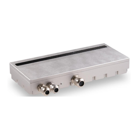
Dalsa A CIS Series User manual

Linea HS Series Camera User's Manual Contents •1
800mm Configuration Shown
©2022 Teledyne Digital Imaging, Inc.
All information provided in this manual is believed to be accurate and reliable. No responsibility is
assumed by Teledyne DALSA for its use. Teledyne DALSA reserves the right to make changes to
this information without notice. Reproduction of this manual in whole or in part, by any means, is
prohibited without prior permission having been obtained from Teledyne DALSA.
Microsoft and Windows are registered trademarks of Microsoft Corporation in the United States and
other countries. Windows, Windows 7, Windows 8 are trademarks of Microsoft Corporation.
All other trademarks or intellectual property mentioned herein belong to their respective owners.
Document Date: 16th December, 2021
Document Number: 03-032-25022-00
AxCIS Series
Preliminary AxCIS Features Manual
Monochrome, CIS Line Scan
sensors | cameras | frame grabbers | processors | software | vision solutions
03-032-25022-00
Revision 01
www.teledynedalsa.com

2•Contents Preliminary Linea HS Series Camera User's Manual
About Teledyne DALSA
Teledyne DALSA, a business unit of Teledyne Digital Imaging Inc., is an international high-
performance semiconductor and Electronics Company that designs, develops, manufactures, and
markets digital imaging products and solutions, in addition to providing wafer foundry services.
Teledyne DALSA offers the widest range of machine vision components in the world. From industry-
leading image sensors through powerful and sophisticated cameras, frame grabbers, vision
processors and software to easy-to-use vision appliances and custom vision modules.
Contents
FIGURES 5
AXCIS SERIES CAMERA FEATURES 5
DESCRIPTION 5
CIS Optical Technology 6
CAMERA HIGHLIGHTS 8
Common Features 8
Resolution 8
Programmable Features 8
Applications 8
PART NUMBERS AND SOFTWARE REQUIREMENTS 9
SUPPORTED INDUSTRY COMMUNICATIONS STANDARDS 10
GenICam™ 10
Image Data Cables and Transceivers 11
MECHANICAL DRAWINGS 13
PRECAUTIONS 14
Electrostatic Discharge and the CMOS Sensors 14
INSTALL &CONFIGURE FRAME GRABBER &SOFTWARE 15
Using Sapera CamExpert 15
CamExpert Panes 16
SETTING UP FOR IMAGING 18
Camera I / O Connectors 18
Powering the Module 18
Power and GPIO Connections 20
Establishing Module Communications 22
Selecting the Data Format 22
Establishing Data Integrity 23
CAMERA FEATURES 24
SYNCHRONIZING TO OBJECT MOTION 24
Acquiring Images: Triggering the Camera 24
Measuring Line (Trigger) Rate 25
Maximum Line Rate 25
Minimum Line Rate 25
Scan Direction 25
Camera Orientation 27

Linea HS Series Camera User's Manual Contents •3
Automatic Sensor Alignment 27
Maintaining Image Alignment 28
Dual Exposure Mode (HDR) 29
Internal Trigger Mode 30
ESTABLISHING THE OPTIMAL RESPONSE 31
Image Response Uniformity & Flat Field Calibration 31
Saving & Loading a PRNU Set Only 33
Flat Field Calibration Regions of Interest 33
BINNING 34
USING AREA OF INTEREST (AOIS) 35
Steps to Setup Area of Interest for Each Section 36
Rules for Setting Areas of Interest 36
ADJUSTING RESPONSIVITY AND CONTRAST ENHANCEMENT 37
Black Level 37
CHANGING OUTPUT CONFIGURATION 38
Pixel Format 38
ESTABLISHING THE DESIRED OBJECT PIXEL SIZE 38
Encoder Multiplier 38
ENSURING IMAGE ALIGNMENT &RESPONSE LEVEL 39
Object Pixel Size 39
Angle Correction 39
Response Leveling 39
OPTIONAL LED ARRAY CONTROL 40
SAVING &RESTORING CAMERA SETUP CONFIGURATIONS 41
Active Settings for Current Operation 42
User Setting 42
Factory Settings 42
Default Setting 42
APPENDIX A: GENICAM COMMANDS 43
CAMERA INFORMATION CATEGORY 44
Camera Information Feature Descriptions 44
Built-In Self-Test Codes (BIST) 47
Camera Power-Up Configuration Selection Dialog 47
Camera Power-up Configuration 47
User Set Configuration Management 48
CAMERA CONTROL CATEGORY 49
Camera Control Feature Descriptions 49
DIGITAL IO CONTROL CATEGORY 52
Digital IO Control Feature Descriptions 52
FLAT FIELD CATEGORY 54
Flat Field Control Feature Description 54
IMAGE FORMAT CONTROL CATEGORY 56
Image Format Control Feature Description 56
FILE ACCESS CONTROL CATEGORY 58
File Access Control Feature Descriptions 58
File Access via the CamExpert Tool 60
CLHS File Transfer Protocol 61
Upload File to Camera 62
Download a List of Camera Parameters 62
TRANSPORT LAYER CONTROL CATEGORY 63
Transport Layer Feature Descriptions 63
ACQUISITION AND TRANSFER CONTROL CATEGORY 65

4•Contents Preliminary Linea HS Series Camera User's Manual
Acquisition and Transfer Control Feature Descriptions 65
APPENDIX B: TROUBLE SHOOTING GUIDE 66
DIAGNOSTIC TOOLS 66
RESOLVING CAMERA ISSUES 69
Communications 69
Image Quality Issues 70
Power Supply Issues 73
DECLARATIONS OF CONFORMITY 73
DOCUMENT REVISION HISTORY 74

Linea HS Series Camera User's Manual Contents •5
Figures
Figure 1: Linea CLHS Dual LC/SFP+ Connector Configuration 11
Figure 2: Single CLHS Connector Configuration 11
Figure 3: CS-FM-04L12A-00 Prototype Mechanical Drawing 13
Figure 4: CS-FM-08L12A/B-50 Prototype Mechanical Drawing 13
Figure 5: CamExpert Frame Grabber Control Window 16
Figure 6. Module I / O Connectors 18
Figure 7: 26-pin high density D-Sub Pin Numbering 20
Figure 8. Image with correct scan direction 26
Figure 9. Image with incorrect scan direction 26
Figure 10: Example of Object Movement and Module Direction 27
Figure 11: 2x2 Binning 34
Figure 12: Black Level, Row Gain and System Gain Processing Chain 37
Figure 13. Relationship Between Camera Settings 41
Figure 14 Example CamExpert Module Information Panel 44
Figure 15: CamExpert Power-Up Configuration Dialog 47
Figure 16: Module Control Panel 49
Figure 17 Digital I/O Control Panel 52
Figure 18: Flat Field Panel 54
Figure 19: Image Format Panel 56
Figure 20: File Access Control Panel 58
Figure 21: File Access Control Tool 60
Figure 22: File Upload Completed Message Box 60
Figure 23: Transport Layer Panel 63
Figure 24: Acquisition & Transfer Control Panel 65
Figure 25: CamExpert Voltage & Temperature Features 66
Figure 26: CamExpert Test Pattern Feature 67
AxCIS Series Camera Features
Description
This user manual is preliminary.
This document details the camera features. Please contact the factory for performance
specifications or any other technical details.
Teledyne DALSA introduces a breakthrough CMOS line scan CIS format module with unprecedented
speed, responsivity and low noise.
Over time, Teledyne DALSA will release the complete range of CIS modules from less than 300mm
to 1500mm. The name of this product family is AxCIS. Initial offering has 400 and 800mm scan
widths at 600dpi or 900dpi resolution with optional integrated white LED illumination

6•AxCIS Series Camera Features Linea HS Series Camera User's Manual
The AxCIS incorporates Teledyne DALSA’s latest CMOS sensor technology in a staggered
arrangement that ensures 100% image coverage without interpolation and self-calibration
capabilities to ensure image uniformity and alignment.
These cameras have a maximum line rate of 120 kHz with up to 900dpi resolution for any length of
module.
The camera uses the Camera Link HS™ interface—the industry standard for a very high-speed fiber
optic camera interface with long transmission distances and cable flexing requirements
Teledyne DALSA’s AxCIS modules and compatible frame grabbers combine to offer a complete
solution for the next generation of automatic optical inspection systems.
These modules are recommended when there is restricted space available to locate the imaging
system. Teledyne DALSA’s AxCIS modules are well suited for detecting defects at high speeds over
a large fields of view where the ‘telocentric like’ properties of the Selfoc Lens Array (SLA) are
desirable for limited measurement purposes and consistent defect classification.
Preliminary Monochrome Models
Prototype Part Number
AxCIS part
number
Description
CS-FM-04L12A-00
AX-FM-04A12H-00
400mm field of view, 600dpi, maximum line rate of 120 kHz,
monochrome output, Camera Link HS LC fiber optic connectors. Note:
Prototype includes integrated lighting, however, AxCIS requires 2 of AC-
LE-10008-00 for integrated lighting.
CS-FM-04L12B-00
AX-FM-04B12H-00
400mm field of view, 900dpi, maximum line rate of 120 kHz,
monochrome output, Camera Link HS LC fiber optic connectors. Note:
Prototype includes integrated lighting, however, AxCIS requires 2 of AC-
LE-10008-00 for integrated lighting.
CS-FM-08L12A-00
AX-FM-08A12H-00
800mm field of view, 600dpi, maximum line rate of 120 kHz,
monochrome output, Camera Link HS LC fiber optic connectors. Note:
Prototype includes integrated lighting, however, AxCIS requires 2 of AC-
LE-10008-00 for integrated lighting.
CS-FM-08L12B-00
AX-FM-08B12H-00
800mm field of view, 900dpi, maximum line rate of 120 kHz,
monochrome output, Camera Link HS LC fiber optic connectors. Note:
Prototype includes integrated lighting, however, AxCIS requires 2 of AC-
LE-10008-00 for integrated lighting.
CIS Optical Technology
AxCIS combines a Selfoc Lens Array (SLA), an linear array of TeledyneDALSA CMOS sensors,
Image processing, power management and optional integrated LED illumination to provide a
complete imaging solution. Industry refers to this configuration as Contact Image Sensor (CIS)
technology.
What make CIS unique is the SLA which is an optical device consisting of an array of Gradient
Index Lenses (GRIN’s) that used at a magnification of 1x, reproducing the object at the sensors
image plane in a line of the over long lengths with a short working distance. This allows for a very
compact imaging module that can be in confined spaces.

Linea HS Series Camera User's Manual AxCIS Series Camera Features •7
The SLA optical arrangement also ensures a uniform image over the entire field of view unlike
regular lenses that can cause image variation due to the angular field of view. This can be helpful
for measurement purposes and consistent defect characteristic’s ensuring reliable classification

8•AxCIS Series Camera Features Linea HS Series Camera User's Manual
Camera Highlights
Common Features
•Staggered arrangement ensuring no lost pixels
•600dpi or 900dpi resolution
•Highly sensitive multi line CMOS sensors
•Up to 120 kHz line rates
•Very low noise
•Bidirectionality
•Horizontal and Vertical Binning
•Robust Camera Link HS interface
•LC Camera Link HS control & 10gb/s data connectors
•Single or dual row exposure mode for high dynamic range
•Optional integrated white LED illumination
•Compact enclosure
•13.72mm working distance
•0.6mm depth of field
•Single 24v+/-10% power supply
Resolution
•Monochrome Models: 600pdi and 900dpi pixel resolution
•Multiple lengths feasible in 100mm increments
•400mm and 800mm lengths with initial offering.
Programmable Features
•Single or dual row operation with independent exposure control
•Multiple areas of interest for data reduction
•Region of interest for easy calibration of shading correction
•Flexible gain and offset control
•Module angle correction
•Encoder input multiplier
•Save & restore multiple user configurations
•Intensity control of optional LED arrays
•Test patterns & diagnostics
Applications
•Flat panel inspection
•Web & textile inspection
•Printed circuit board inspection
•3D printer inspection
•High throughput applications

Linea HS Series Camera User's Manual AxCIS Series Camera Features •9
Part Numbers and Software Requirements
The camera is available in the following configurations:
Note: The prototypes are always shipped with LED arrays where the user can readily remove them
if required. However, the Standard AxCIS cameras require lighting to be ordered separately.
Table 1: Camera Models Comparison
Part Number
Resolution
Field of View
Max. Line Rates
Pixel Size
Control & Data
Monochrome
CS-FM-04L12A-00
&
AX-FM-04A12H-00
600dpi
400mm
120kHz single
mono /60 kHz Dual
Exposure mono
42x42um
Camera Link HS
LC fiber optic
CS-FM-08L12A-00
&
AX-FM-08A12H-00
600dpi
800mm
120kHz single
mono /60 kHz Dual
Exposure mono
42x42um
Camera Link HS
LC fiber optic
CS-FM-08L12B-00
&
AX-FM-08B12H-00
900 dpi
800mm
120kHz single
mono /60 kHz Dual
Exposure mono
28x28 µm
Camera Link HS
LC fiber optic

10 •AxCIS Series Camera Features Linea HS Series Camera User's Manual
Table 2: Frame Grabber
Compatible Frame grabber
Linea HS Model
Teledyne DALSA Xtium2-CLHS FX8 (OR-A8S0-FX840)
All models
Table 3: Software
Software
Product Number / Version Number
Camera firmware
Embedded within camera
GenICam™ support (XML camera description file)
Embedded within camera
Sapera LT, including CamExpert GUI application and GenICam for Camera Link
imaging driver
Latest version on the
Teledyne DALSA Web site
Supported Industry Communications Standards
GenICam™
The camera is GenICam compliant and implements a superset of the GenICam Standard Features
Naming Convention specification V1.5.
This description takes the form of an XML device description file using the syntax defined by the
GenApi module of the GenICam specification. The camera uses the GenICam Generic Control
Protocol (GenCP V1.0) to communicate over the Camera Link HS command lane.
For more information see www.genicam.org.

Linea HS Series Camera User's Manual AxCIS Series Camera Features •11
AxCIS module is Camera Link HS version 1.0 compliant. Camera Link HS is the next generation of
high-performance communications standards. It is used where an industrial digital camera
interfaces with a single or multiple frame grabbers and with data rates exceeding those supported
by the LVDS based Camera Link standard.
The AxCIS modules sections come with a dual SFP+ XCVR cage where one or two 10G XCVR
modules can be added along with associated LC Fiber Optic cables as required to support image
data bandwidth requirements.
Note that the SFP+ XCVR are not included with the module and can be ordered separately from
TeledyneDALSA or from another vendor who supplies compliant modules.
Frame Grabber CIS Module
LC Connectors
Fiber Optics
Image Data
Channel Command
Channel
SFP+ XCVR Module
SFP+ XCVR Module
SFP+ XCVR Module
SFP+ XCVR Module
Figure 1: Linea CLHS Dual LC/SFP+ Connector Configuration
Figure 2: Single CLHS Connector Configuration
The command channel is used by the frame grabber to send commands, configuration and
programming data to the camera and to receive command responses, status and image data from
the camera. Image data and command transmissions use CLHS X protocol (64b / 66b) at the
default speed of 10 Gb/s per cable.
Image Data Cables and Transceivers
The fiber optic cables require LC connections and XCVR modules on both ends of the cable.
LC is a small-form factor fiber optic connector that uses a 1.25 mm ferrule, half the size of a
standard connector. These cables are in wide use in the telecommunications industry and available
in many lengths.
The distance through which the data can be transmitted depends on the type of fiber optic used.
Recommended fiber optic cables are types OM3 and OM4.
OM4 is used for distances > 300 m, but also requires SFP+ transceiver module changes.
Contact Teledyne DALSA Support for more information on recommended cables.
Table 4: LC Fiber Optic Cable Details
Category
Fiber Diameter
Mode
Max Distance
OM3
50 µm
Multimode
< 280 m

12 •AxCIS Series Camera Features Linea HS Series Camera User's Manual
OM4
50 µm
Multimode
> 300 m
The following is available to support the specific fiber optic cabling needs of the user. The individual
parts can be ordered from TeledyneDALSA or a third party.
Individual Parts
Dalsa Part #
Child Part
Mfg'er part#
Description
MFG
720-00335-
00
OM3-LC-LC-DX-FS-10M-
PVC
CABLE;Fiber Optic
Patch;10M
Fiberstore
720-00336-
00
OM3-LC-LC-DX-FS-15M-
PVC
CABLE;Fiber Optic
Patch;15M
Fiberstore
720-00337-
00
OM3-LC-LC-DX-FS-30M-
PVC
CABLE;Fiber Optic
Patch;30M
Fiberstore
720-00338-
00
OM3-LC-LC-DX-FS-50M-
PVC
CABLE;Fiber Optic
Patch;50M
Fiberstore
AC-CA-00220-
00-R
730-00091-
00
SFP-10GSR-85
XCVR MOD;10GBASE-SR
SFP+
Fiberstore

Linea HS Series Camera User's Manual AxCIS Series Camera Features •13
Mechanical Drawings
Figure 3: CS-FM-04L12A-00 Prototype Mechanical Drawing
Figure 4: CS-FM-08L12A/B-50 Prototype Mechanical Drawing

14 •AxCIS Series Camera Features Linea HS Series Camera User's Manual
Precautions
Read these precautions before using the CIS module.
Confirm that the module’s packaging is undamaged before opening it. If the packaging is damaged
please contact the related logistics personnel.
Do not open the housing of the module. The warranty is voided if the housing is opened.
Keep the module housing temperature in a range of 0 °C to +50 °C during operation. The module
can measure its internal temperature. Use this feature to record the internal temperature of the
module when it is mounted in your system and operating under the worst-case conditions. The
module will stop outputting data if its internal temperature reaches +80 °C.
Do not operate the module in the vicinity of strong electromagnetic fields. In addition, avoid
electrostatic discharging, violent vibration and excess moisture.
To clean the device, avoid electrostatic charging by using a dry, clean absorbent cotton cloth
dampened with a small quantity of pure alcohol. Do not use methylated alcohol. To clean the
surface of the camera housing, use a soft, dry cloth. To remove severe stains, use a soft cloth
dampened with a small quantity of neutral detergent and then wipe dry. Do not use volatile
solvents such as benzene and thinners, as they can damage the surface finish.
Though this module supports hot plugging, it is recommended that you power down and disconnect
power to the module before you add or replace system components.
Electrostatic Discharge and the CMOS Sensors
Image sensors and the module’s housing can be susceptible to damage from severe electrostatic
discharge (ESD). Electrostatic charge introduced to the sensor windows surface can induce charge
buildup on the underside of the window. The charge normally dissipates within 24 hours and the
sensors returns to normal operation.

Linea HS Series Camera User's Manual AxCIS Series Camera Features •15
Install & Configure Frame Grabber & Software
Because of the high bandwidth of these modules, a compatible Teledyne DALSA frame grabber
(Xtium2-CLHS PX8 (OR-A8S0-FX840), or equivalent, is recommended. The frame grabber
requirements for the 8K and 16K cameras differ. Follow the manufacturer’s installation instructions.
For more details see the Teledyne DALSA website:
http://www.teledynedalsa.com/en/products/imaging/frame-grabbers
A GenICam compliant XML device description file is embedded with the module firmware. It allows
GenICam compliant applications to recognize the module’s capabilities, once connected.
Installing Sapera LT gives you access to the CamExpert GUI, a GenICam compliant application.
Using Sapera CamExpert
CamExpert is the camera interfacing tool supported by the Sapera library. When used with the
module, CamExpert allows a user to test all module operating modes. In addition, CamExpert can
be used to save the module’s user settings configuration to the module or to save multiple
configurations as individual module parameter files on the host system (*.ccf).
CamExpert can also be used to upgrade the module’s software.
An important component of CamExpert is its live acquisition display window. This window allows
verification of timing or control parameters in real-time, without need for a separate acquisition
program.
The central section of CamExpert provides access to the camera features and parameters.
Note: The availability of features depends on the CamExpert user setting. Not all
features are available to all users. The examples shown are for illustrative
purposes and may not entirely reflect the features and parameters available from
the module model used in your application.

16 •AxCIS Series Camera Features Linea HS Series Camera User's Manual
CamExpert Panes
CamExpert, first instance: select Camera Link HS Mono#1 using the Device drop-down menu.
Figure 5: CamExpert Frame Grabber Control Window
The CamExpert application uses panes to organize the selection and configuration of camera files
or acquisition parameters.
Device Selector pane: View and select from any installed Sapera acquisition device. Once a
device is selected, CamExpert will only show acquisition parameters for that device. Optionally,
select a camera file included with the Sapera installation or saved previously.
Parameters pane: Allows the viewing or changing of all acquisition parameters supported by the
acquisition device. CamExpert displays parameters only if those parameters are supported by the
installed device. This avoids confusion by eliminating parameter choices when they do not apply to
the hardware in use.
Display pane: Provides a live or single frame acquisition display. Frame buffer parameters are
shown in an information bar above the image window.

Linea HS Series Camera User's Manual AxCIS Series Camera Features •17
Control Buttons: The display pane includes CamExpert control buttons. These are:
Acquisition control button:
Click once to start live grab, click again to stop.
Single frame grab:
Click to acquire one frame from device.
Trigger button:
With the I/O control parameters set to Trigger Enabled, click to send a
single trigger command.
CamExpert display controls:
(these do not modify the frame buffer data)
Stretch image to fit, set image display to original size, or zoom the
image to virtually any size and ratio.
Histogram / Profile tool:
Select to view a histogram or line/column profile during live
acquisition or in a still image.
Output Message Pane: Displays messages from CamExpert or the device driver.
Multiple Instances of CamExpert: Modules longer than 500mm incorporate multiple imaging
sections each with a separate interface to the host frame grabber. These are treated as separate
modules each requiring their own CamExpert window. Note that modules with multiple imaging
sections ensure image alignment is maintained across the entire field of view. A single Xtium2-
CLHS PX8 frame grabber can support up to four imaging sections if each has a single LC cable or
two imaging sections if each has a two LC cables to the frame grabber. For more details on how to
set up multiple instances of CamExpert see the Teledyne DALSA website:
http://www.teledynedalsa.com/en/products/imaging/frame-grabbers
At this point you are ready to start operating the camera, acquire images, set camera functions
and save settings.

18 •AxCIS Series Camera Features Linea HS Series Camera User's Manual
Setting Up for Imaging
1 23 4 65
Figure 6. Module I / O Connectors
Camera I / O Connectors
1) Factory use only
2) Data and control connectors –two LC Fiber pairs
3) LED status indicators
4) Power and GPIO connectors: +24 V DC, two I/P, four O/P, 26 pin HD D-Sub connector
5) LED array#1 power. Note: Is being changed
6) LED array#2 power. Note: Is being changed
Powering the Module
WARNING: When setting up the camera’s power supply follow these guidelines:
•The 24V supply must be isolated from frame ground of the power supply to
prevent potential ground loop issues.
•Before connecting power to the module, verify the power supply voltage.
•Apply the +24 V. Incorrect voltages may damage the camera.
•There will be no current draw and the unit will not turn on below 20.4V
•Protect each module section with a 5 amp slow-blow fuse or circuit breaker between the
power supply and the module.
•Do not use the shield on a multi-conductor cable for ground.
•Keep power leads as short as possible in order to reduce voltage drop.
•Use high quality supplies in order to minimize noise.

Linea HS Series Camera User's Manual AxCIS Series Camera Features •19
Note: If your power supply does not meet these requirements, then the module
performance specifications are not guaranteed.

20 •AxCIS Series Camera Features Linea HS Series Camera User's Manual
Power and GPIO Connections
The module uses a single 26-pin high density D-Sub male connector for power, trigger and strobe
signals.
26-pin high density D-Sub Signal Details
The following figure shows the pinout identification when looking at the module’s 26-pin male HD
D-Sub connector. The table below lists the I/O signal connections.
19
10 18
19 26
Figure 7: 26-pin high density D-Sub Pin Numbering
Table 5: 12-pin Hirose Pin Assignment
Pin Number
Signal Input /
Output
Signal Details
Notes
1
Input
Encoder Phase A+
RS422 Signal
2
Input
Encoder Phase A-
RS422 Signal
3
Input
Encoder Phase B+
RS422 Signal
4
Input
Encoder Phase B-
RS422 Signal
5
+24V Power
6
+24V Power
7
Reserved. Do not connect
8
Power Ground
9
Power Ground
10
Output
Line#1+
RS422 Signal
11
Output
Line#1-
RS422 Signal
12
Output
Line#2+
RS422 Signal
13
Output
Line#2-
RS422 Signal
14
+24V Power
15
+24V Power
16
Reserved. Do not connect
17
Power Ground
18
Power Ground
19
Output
Line#3+
RS422 Signal
20
Output
Line#3-
RS422 Signal
21
Output
Line#4+
RS422 Signal
Table of contents
Other Dalsa Security Sensor manuals