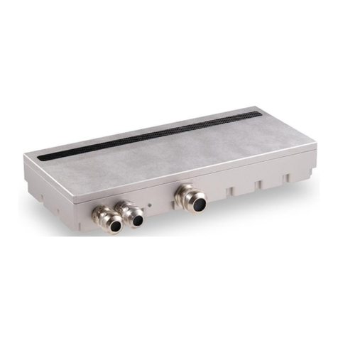
Dalsa Shad-o-Box 2K HS User manual

Shad-o-Box 1K/2K HS User Manual p. 2
© 2018 Teledyne DALSA. All information provided in this manual is believed to be accurate and reliable. No responsibility is
assumed by Teledyne DALSA for its use. Teledyne DALSA reserves the right to make changes to this information without notice.
Reproduction of this manual in whole or in part, by any means, is prohibited without prior permission having been obtained from
Teledyne DALSA.
About Teledyne DALSA
Teledyne DALSA is an international high performance semiconductor and electronics company that designs, develops,
manufactures, and markets digital imaging products and solutions, in addition to providing semiconductor products and services.
Teledyne DALSA’s core competencies are in specialized integrated circuit and electronics technology, software, and highly
engineered semiconductor wafer processing. Products and services include image sensor components; electronic digital cameras; X-
ray detectors; vision processors; image processing software; and semiconductor wafer foundry services for use in MEMS, high-
voltage semiconductors, image sensors and mixed-signal CMOS circuits.
Contact Information
Please feel free to contact the Teledyne DALSA sales office nearest you to place an order, obtain more detailed
information or in case you encounter any problem operating the detector:
Americas
765 Sycamore Drive
Milpitas, CA 95035
USA
Tel: +1 408-736-6000
Fax: +1 408-736-6001
Europe
High Tech Campus 27 (M/S 14)
5656 AE Eindhoven
The Netherlands
Tel: +31 40 2599000
Fax: +31 40 2599005
Asia Pacific
Ikebukuro East 13F
3-4-3 Higashi Ikebukuro
Toshima-ku, Tokyo
Japan
Tel: +81 3-5960-6353
Fax: +81 3-5960-6354

Shad-o-Box 1K/2K HS User Manual p. 3
Table of Contents
1. Safety Information..........................................................................................................................5
Installation Warning ......................................................................................................................................5
Safety Statement............................................................................................................................................5
No User Serviceable Components .................................................................................................................5
Disposal of Product........................................................................................................................................5
2. EMC compliance............................................................................................................................6
Warning .........................................................................................................................................................6
3. System precautions.........................................................................................................................6
Warning:........................................................................................................................................................6
Static precautions...........................................................................................................................................6
Installation Precautions..................................................................................................................................6
Service by Qualified Personnel Only.............................................................................................................6
4. Detector Maintenance....................................................................................................................7
Protecting the Detector Front Cover..............................................................................................................7
Cleaning the Detector Body and Front Cover................................................................................................7
Periodic Maintenance ....................................................................................................................................7
Calibration .....................................................................................................................................................7
5. Specifications..................................................................................................................................8
6. Connectors, Cables and Status Indicators .....................................................................................9
7. Setting up the Detector.................................................................................................................10
GigE Network Adapter................................................................................................................................10
Connect Ethernet cable................................................................................................................................10
Connect power cable....................................................................................................................................10
Status Light..................................................................................................................................................10
Software Installation....................................................................................................................................10
8. Software Installation and Setup....................................................................................................11
Operating Systems Support .........................................................................................................................11
Obtain software............................................................................................................................................11
Sapera LT and CamExpert Installation........................................................................................................11
Optimizing Settings .....................................................................................................................................12
Connecting...................................................................................................................................................15
Checking detector status and information in Gigabit Ethernet ....................................................................15
9. Acquiring Images..........................................................................................................................16
To snap an image:........................................................................................................................................16
To grab multiple images:.............................................................................................................................16
10. Synchronization Modes ................................................................................................................17
Free running Mode ......................................................................................................................................17

Shad-o-Box 1K/2K HS User Manual p. 4
Shuttering.....................................................................................................................................................17
11. Mechanical Drawings ..................................................................................................................18
Revision History..........................................................................................................................................................20

Shad-o-Box 1K/2K HS User Manual p. 5
1. Safety Information
Installation Warning
The operators of this equipment are responsible for the safe and prudent installation of the detector in their own
system. All X-ray sources and controls, shielding, personnel safety monitoring devices, and personnel safety
precautions involved in the acquisition and display of data are the responsibility of the end user.
Safety Statement
The general safety precautions that follow must be observed during all phases of installation, operation, service and
repair of this system. Failure to comply with these precautions, or with specific warnings noted in this manual,
violates the safety standards of design, manufacture and the intended used of this system. Teledyne DALSA
assumes no responsibility for the user’s failure to comply with these requirements.
Warning: This digital camera system, when installed, is subject to exposure from X-rays during operation.
To ensure personnel safety, it is necessary that a radiation meter be used to check for radiation leakage after
installation of the digital camera in the end users system.
Teledyne DALSA assumes no responsibility for the proper installation of X-ray shielding, X-ray shield enclosure
testing, or safe and prudent operation of the camera system in the end user's installation. It is the end users
responsibility to ensure that local and federal guidelines regarding the installation and operation of X-ray sources are
followed.
For those parties supplying the power requirements to the Shad-o-Box HS, the voltage specifications must be strictly
adhered to or the system will no longer be considered covered under warranty.
No User Serviceable Components
There are no components in this system which need to be replaced, modified, or adjusted by the end user. Please
contact Teledyne DALSA Support for assistance if needed.
Safety Warning: Tampering with this product voids the warranty and may degrade the detectors image quality,
resulting in a possibly unsafe condition.
The system has been designed to minimize the amount of interference it may generate in a typical installation. This
equipment generates and can radiate radio frequency energy and, if not installed and operated in accordance with the
instructions, may cause harmful interference to other devices in the area.
Disposal of Product
This detector does not contain batteries. Dispose of the unit in accordance with local regulatory guidelines.

Shad-o-Box 1K/2K HS User Manual p. 6
2. EMC compliance
To ensure EMC compliance, follow these specific guidelines:
Ensure that all cable shields have a 360electrical connection to the connector.
Fasten and secure all connectors.
Warning
The detector can influence the performance of very sensitive equipment.
Strong EMC disturbances can influence the detector’s performance.
3. System precautions
The following are precautions that must be taken in order to prevent possible damage to your Teledyne DALSA
Detector system:
Warning:
The use of accessories, power supplies and cables other than those supplied or specified, with the exception of
cables sold by Teledyne DALSA as replacement parts, may result in increased emission or decreased immunity of
the Shad-o-Box HS Detector.
Static precautions
Observe proper ESD/static control procedures when handling system
components. The use of properly grounded wrist strap is highly recommended.
Installation Precautions
Never connect or disconnect cables while power to the detector is on. Damage to the detector electronics will occur
if the cables are connected and/or disconnected while the detectors power is on.
Service by Qualified Personnel Only
This equipment is to be installed by a qualified technician only. The system can only be used in conjunction with a
properly installed X-ray source with the appropriate shielding and a properly configured computer workstation that
meets the minimum system requirements discussed later in this manual.

Shad-o-Box 1K/2K HS User Manual p. 7
4. Detector Maintenance
Before performing any of the following operations, make sure that the power to the detector is switched OFF.
Protecting the Detector Front Cover
The imaging area is marked on the front cover of the detector and should be treated with extreme care, as scratches
or debris in this area may produce artifacts in the X-ray image. If visible scratches are present, X-ray test images
should be taken to ensure that the scratches do not adversely affect the image quality.
Cleaning the Detector Body and Front Cover
The detector body and front cover can be cleaned with a mild, non-abrasive cleanser such as isopropyl alcohol.
Place a small amount of cleanser on a soft cloth and rub gently over the detector body surface. Wipe off with a clean
soft cloth. Do not use any harsh cleansers or solvents that may damage the paint or other finishes on the detector.
In the event of detector exposure to bio-hazardous materials, proper cleaning procedures should be undertaken prior
to removal or maintenance of the detector.
Periodic Maintenance
No periodic maintenance or service is needed.
Calibration
To have the best image performance the raw image data output from the detector should be corrected at the host by
using dark offset and flat field correction. It is advisable to re-calibrate the dark offset image as frequently as
feasible during detector standby. The raw flat field image should be re-calibrated at least once every year.
The detector can contain deviating and/or not working pixels. To have the best possible image quality it is advised to
perform a defect pixel correction at the host. Update the defective pixel map at least once every year.

Shad-o-Box 1K/2K HS User Manual p. 8
5. Specifications
Device
Pixels
Active Area
Resolution
Frame Rate
Shad-o-Box 1K HS
1152 x 1300
5.7 x 6.4 cm
49.5 µm
20 fps
Shad-o-Box 2K HS
1152 x 2940
5.7 x 14.6 cm
49.5 µm
10 fps
Detector Specifications
Units
Typ. dark current (23°C)(1)
12
ADU/s(2)
Read noise (rms)
4-8
ADU
Typ. dynamic range
3000:1
Digitization
14
bits
Image lag
< 0.1
%
Non-linearity (10..90%FS)
< 1.5
%
Readout period(3)
45
ms
Output data rate
40
MHz
(1) dark current doubles approx. every 8°C
(2) ADU = Analog-Digital Unit 1 LSB (Least Significant Bit)
(3) time required to transfer image from sensor to camera memory
Camera Specifications
Units
Typical supply voltage
12.0
Volts
Supply voltage range
11 to 13
Volts
Maximum supply current
1.0
Amps
Typical power dissipation
< 10
Watts
Data interface
GigE
General Specifications
Units
Operating Temperature
10 to 40
°C
Storage Temperature
-10 to +55
°C
Humidity (non-condensing)
10 to 80
% R.H.
Weight
< 1.0
kg

Shad-o-Box 1K/2K HS User Manual p. 9
6. Connectors, Cables and Status Indicators
The Shad-o-Box HS detectors use the following connectors:
An RJ-45 connector for Gigabit Ethernet signals, data signals
o CAT5E or CAT6 Ethernet cable
One 2-pin Lemo connector for power
o Lemo EGG.0B.0302
o Mating connectors:
elbow type: FHG.0B.302.CLAD52Z
straight type: FGG.0B.302.CLAD52
Detector Status LED
The detector is equipped with a color LED used to display the status of the detector’s operation. The table below
summarizes the operating states of the detector and the corresponding LED states.
Color of Status LED
Meaning
1
Off
No power
2
Green
Detector is operational
pin
Description
1
Supply voltage (+12V/ 2A)
2
Ground
The power input is protected by a
resettable fuse. If the fuse is
activated, power cycle (off/on)
the detector to reset.

Shad-o-Box 1K/2K HS User Manual p. 10
7. Setting up the Detector
GigE Network Adapter
If the computer to be used with the detector does not have a Gigabit network adapter or second built in Gigabit NIC,
a PCI bus Gigabit NIC needs to be installed. Typically under Windows XP the PCI Gigabit NIC is recognized
automatically when Windows boots. An example of a high performance NIC is the Intel PRO/1000 MT adapter.
Review the NIC documentation concerning any special driver required for Windows. Install the PCI bus Gigabit
NIC as described by the NIC manufacture's documentation.
Connect Ethernet cable
Connect the Ethernet cable from the detector to the computer Ethernet jack. Secure the RJ-45 connector to the
detector.
Connect power cable
Connect a power cable from the detector to a +12V power supply.
Status Light
Verify that the status light is solid green.
Software Installation
Refer to the next chapter for instructions on installing and running the detector software.

Shad-o-Box 1K/2K HS User Manual p. 11
8. Software Installation and Setup
Operating Systems Support
The current released GigE Vision framework supports up to Windows 10.
For Linux the Teledyne DALSA GigE Vision Application Programmers Interface (API) for Linux is available.
For additional support please contact our support team for the software and the latest status.
Obtain software
CD
Check the CD that shipped with your detector for installation files for CamExpert, the GigE driver and/or the
ShadoCam software. To obtain the latest versions, or software for a newer operation system, it may be necessary to
go to the Teledyne DALSA website for the latest updates.
Website
Visit the Teledyne DALSA website to download the latest free version of the Sapera LT SDK, including the
CamExpert image viewer:
http://www.teledynedalsa.com/imaging/products/software/sapera/lt/download/
The download is free after filling out the on-line registration form. Make sure to select “Full SDK” as your
download option.
Sapera LT and CamExpert Installation
A link to download the software will be emailed to you after submitting the application. Complete the download
process and run the installation file (e.g. “SaperaLT80xSDKSetup.exe”).
CamExpert is an image viewer designed to evaluate your detector. The Sapera SDK is a set of development tools
and documentation for creating your own software for interfacing to the product. Please download the appropriate
materials and follow the instructions that are part of that download.
The Sapera SDK installation also contains a large number of helpful example projects to help you get started with
integration the detector into your own application software. For additional examples specific to the Shad-o-Box HS
detector please contact our support team at the contact info listed on page 2 of this manual.
GigE Vision framework for Sapera LT installation
The GigE Vision framework installs the GigE Vision Module for Sapera and includes the Network Imaging package
which is required to access a GigE Vision detector.
Refer to the “GigE Vision Module for Sapera” user manual and “Network Imaging Module for Sapera LT” user
manual which are included in the installation.

Shad-o-Box 1K/2K HS User Manual p. 12
Optimizing Settings
The performance of the gigabit Ethernet connection on the host computer generally can be improved by adjusting
some settings in the NIC. The below advices refer to the Intel Gigabit CT desktop adaptor. For a more detailed
explanation please refer to “Network Optimization Guide (PDF)” and “Network Imaging User’s Manual (PDF)”
which is part of the Sapera LT software package.
To reduce the interrupt overhead in the host the following settings in the NIC are advised.
Packet Size
For a good Gigabit Ethernet connection with minimal packet resend conditions, host computer performance can
generally be improved by increasing the data packet size. Each streaming video packet causes an interrupt in the
host computer. Therefore increasing the packet size reduces the CPU overhead required to handle video data from
the GigE Vision detectors.
A standard packet can have a size up to 1500 bytes. Many network cards support a jumbo packet mode that can
extend that size up to 16Kbytes. In theory, a packet could be as large as 16 KB, but the CRC (cycle redundancy
check) containing the checksum of each packet is not as efficient when the packet size grows larger than 9000 bytes.
For this reason we advise to set the packet size to 9014 bytes (jumbo packet enabled).
Interrupt Moderation
Normally, each time a packet is received by the network card, the associated driver will receive an interrupt.
Obviously, when the packet rate is very high (that is, at high transfer rate which is common for GigE Vision
systems), this represents significant overhead. Most network cards have introduced an interrupt moderation mode
where the card waits to have received a certain number of packets over a maximum period of time before issuing the
interrupt. This helps reduce the burden on the CPU as it can process multiple packets during the same interruption.
The Intel Gigabit CT Network adapter provides a configuration parameter to manually adjust the NIC interrupt
moderation rate. By default the NIC driver sets this to Adaptive where the interrupt rate automatically balances
packet transmission interrupts and host CPU performance. In most cases no manual optimization of the Interrupt
Moderation Rate parameter is required.
In some conditions, video frames from the GigE Vision detector may be transferred to the host display or memory
buffer as data bursts instead of a smooth continuous stream. The NIC may be over-moderating acquisition interrupts
to avoid over-loading the host CPU with interrupts. If priority is required for acquisition transfers (i.e. a more real-

Shad-o-Box 1K/2K HS User Manual p. 13
time system response to the detector transfer) then the moderation rate should be set to “maximum” by manually
adjusting the NIC parameter.
In the end, this is a compromise:
1. Enable interrupt moderation to minimize CPU usage, at the expense of a slight increase in latency
(recommended).
2. Disable interrupt moderation to favor responsiveness of real-time system with a drawback in CPU usage.
In most situations, extra latency introduced by interrupt moderation is very low and thus the gain on CPU
performance becomes more beneficial.
Receive Buffers
Under certain conditions the host PC system CPU may be busy with tasks other than the imaging application.
Incoming image packets remain in the PC memory allocated to store packets instead of immediately being copied
into the image buffer. By increasing the number of NIC (network interface card) receive buffers, more incoming
image packets can be stored by the NIC before it must start discarding them. This provides more time for the PC to
switch tasks and move image packets to the image buffer.
Not all network boards allow increases to their receive buffer count. Among those that do, different versions will
have different maximum receive descriptor values.
We recommend increasing the receive buffer size to the maximum permitted by the network card, in order to
provide more buffering capacity when needed.

Shad-o-Box 1K/2K HS User Manual p. 14
UDP Checksum Offload (IPv4)
Disable UDP Checksum Offload (IPv4).
Flow Control
The GigE Vision standard defines an inter-packet delay that can be used to manage flow control (i.e. the speed at
which stream packet can be output to the network). This is useful when connecting multiple detectors to the same
port of the network card, or when the network card/Ethernet switch (if used) is simply too slow to process those
packets. A careful selection of equipment will ensure that the network equipment is fast enough to handle data

Shad-o-Box 1K/2K HS User Manual p. 15
transmitted to the wire-speed of 1 Gigabit per second. Therefore, inter-packet delay is typically only used when
multiple detectors are connected to the same port of the network card, through an Ethernet switch.
It is important to consider that inter-packet delay inserts a minimum delay between image packets to spread packet
transmission over a longer period of time. This can directly impact system latency as more time than could be
necessary is put in between those packets. The best approach for real-time imaging is to dedicate a different network
port to each detector. This way, the inter-packet delay can be eliminated in many cases.
Some network equipment also supports the optional IEEE802.3 PAUSE mechanism. This is a low-level handshake
to ensure the receiver of the packets is not overwhelmed by the amount of data. It can propagate a pause signal back
to the transmitter, asking to momentarily stop the data transmission (with a possible impact on the overall system
latency). Again, by combining network equipment that can operate at wire-speed and allocating a different network
interface port for each detector in the system, we can ensure these pause requests will not be used.
Connecting
1. After the install is complete, plug in the detector communication cable.
2. Power up the detector.
3. After powering up the detector, the application automatically detects the detector. This may take up to 1 minute.
Wait until the detector connected indicator in the task bar (shown below) has confirmed that a connection has been
established (the red cross over the camera icon disappears).
Checking detector status and information in Gigabit Ethernet
When you add or remove a detector from the network, it is automatically detected by the GigE server. A manual
network scan can also be launched by right-clicking the camera icon and selecting “Scan Network” from the menu
options. This action will refresh the information of the device connected to the network.
After the detector connection has been established, the status of the connection can be displayed by double-clicking
the camera icon in the task bar. The device status window displays the serial number of the detector that has been
detected on the network and its current status. Additional information with respect to the detector model, serial
number and MAC address is also displayed.
The user can also view the detector and the PC IP addresses in this window. The default assigned detector IP address
can be modified using the Teledyne DALSA Network Configuration Tool, which is part of the installation package.

Shad-o-Box 1K/2K HS User Manual p. 16
9. Acquiring Images
The CamExpert software can be started to acquire images.
The software will display all available device parameters.
The user has the option to either snap an image or to grab multiple images. Snapping an image produces a single
frame, whereas the grabbing process generates multiple frames by operating in a continuous mode.
To snap an image:
Click the Snap button. The Detector has now snapped a single frame. The image appears in the GUI window.
To grab multiple images:
Click the Grab button. The detector is now armed and ready to acquire images in continuous mode.
To stop a Grab process the user must press the Freeze button. After the Freeze button is pressed the detector ignores
any additional triggers and no additional images are acquired.

Shad-o-Box 1K/2K HS User Manual p. 17
10. Synchronization Modes
The detector can be used in combination with either a DC X-ray source or a pulsed X-ray source.
Free running Mode
When using a DC X-ray source:
The detector is operating in a continuous, asynchronous mode. The integration time window equals the frame time
of the detector. Immediately after the readout, the pixels are reset and a new integration period commences. The
frame rate (#frames/second) is equal to 1/(integration time).
When using a pulsed X-ray source:
The figure shows the array row read-out as a function of time. The frame ReadOut containing the image information
is marked blue. The frame integration time is indicated by the horizontal distance between the two slanted ReadOut
lines and the actual image-capture interval is marked with the dark green rectangle.
Row #
Pixel Array
Time
ReadOut
Integration
Time
Frame (N) Frame (N+1)
Trigger Input
Trigger Output
The period of time in between successive frame read-outs (dark green) is used to fire the pulsed X-ray source. The
width of this time-period can be programmed via the detectors command interface by adjusting the
ExtendedExposure(us) parameter. The ExtendedExposure register controls the time between frame ReadOuts.
Shuttering
Please note: the Shad-o-Box 1K/2K HS does not have a shuttering mechanism built into the detector. Therefore, it is
imperative that the x-ray source be shuttered or turned off before readout of the detector begins. Failing to do so may
cause a blur or smear effect in the x-ray image.
In order to ensure that x-ray emissions have completely ceased before the image readout begins; either add a shutter
in front of the x-ray source or use the Readout Delay feature to add time to allow the x-ray source to fully decay.

Shad-o-Box 1K/2K HS User Manual p. 18
11.Mechanical Drawings
Shad-o-Box 1K HS Model (all measurements are in mm):

Shad-o-Box 1K/2K HS User Manual p. 19
Shad-o-Box 2K HS Model (all measurements are in mm):

Shad-o-Box 1K/2K HS User Manual p. 20
Appendix A
Revision History
Revision
Number
Change Description
Revision Date
01
Draft release
May 10, 2016
02
New address
January 12, 2018
03
Added SB2kHS detector
December 11, 2018
This manual suits for next models
2
Table of contents
Other Dalsa Security Sensor manuals