Dalstar 1M60 User manual

1M60 Camera User’s Manual 1
DALSA C32-10010-01
1M60
DS-41-01M60
DS-42-01M60
60 fps 1k x 1k
CCD Camera
User’s Manual and Reference
Doc #: C32-10010
Rev: 01

1M60 Camera User’s Manual 2
DALSA C32-10010-01
1M60 Camera User’s Manual Document Number C32-10010-01
© 2001 DALSA. All information provided in this manual is believed to be accurate
and reliable. No responsibility is assumed by DALSA for its use. DALSA reserves
the right to make changes to this information without notice. Reproduction of this
manual in whole or in part, by any means, is prohibited without prior permission
having been obtained from DALSA.
About DALSA
DALSA specializes in the manufacture, design, research and development of high
performance digital imaging solutions. The DALSTAR 1M60 is part of a product
line that provides the highest spatial resolution at the highest data transfer speed of
any known products in the industry. DALSA’s image sensors and cameras are used
worldwide in document scanning, image capture, surveillance, process monitoring
and manufacturing inspection. DALSA also develops customized products for
specific customers and applications.
All DALSA products are manufactured using the latest state-of-the-art equipment to
ensure product reliability.
DALSTAR refers to all DALSA area scan products.
For further information not included in this manual, or for information on DALSA’s
extensive line of image sensing products, please contact us.
DALSA Sales Offices
DALSA
Waterloo
DALSA
Europe
DALSA
Asia Pacific
605McMurrayRd
Waterloo,ON N2V2E9
Canada
Tel:5198866000
Fax:5198868023
www.dalsa.com
BreslauerStr.34
D-82194Gröbenzell(Munich)
Germany
Tel:+49-8142–46770
Fax:+49-8142–467746
www.dalsa.com
SpaceG1Building,4F
2-40-2Ikebukuro
Toshima-ku,Tokyo171-0014
Japan
Tel: +81 3 5960 6353
Fax:+81 3 5960 6354
www.dalsa.com
DALSA Worldwide Operations
DALSA
Waterloo
DALSA
Colorado Springs
DALSA
Tucson
DALSA
Europe
DALSA
Asia Pacific
605McMurrayRd
Waterloo,ON N2V2E9
Canada
Tel:5198866000
Fax:5198868023
www.dalsa.com
5055CorporatePlazaDrive
ColoradoSprings,CO 80919
USA
Tel:7195997700
Fax:7195997775
www.dalsa.com
3450S.BroadmontDr.Suite#128
Tucson,AZ 85713-5245
USA
Tel:5207917700
Fax:5207917766
www.med-optics.com
BreslauerStr.34
D-82194Gröbenzell(Munich)
Germany
Tel:+49-8142–46770
Fax:+49-8142–467746
www.dalsa.com
SpaceG1Building,4F
2-40-2Ikebukuro
Toshima-ku,Tokyo171-0014
Japan
Tel: +81 3 5960 6353
Fax:+81 3 5960 6354
www.dalsa.com

1M60 Camera User’s Manual 3
DALSA C32-10010-01
1M60 USER’S MANUAL
Contents
1.0 INTRODUCTION TO THE 1M60 CAMERA .............................................................................. 5
CAMERA HIGHLIGHTS ................................................................................................................................5
Features.................................................................................................................................................. 5
Description ............................................................................................................................................. 5
Applications............................................................................................................................................ 5
1.2 IMAGE SENSOR ................................................................................................................................6
1.3 CAMERA PERFORMANCE SPECIFICATIONS....................................................................................... 7
2.0 CAMERA HARDWARE INTERFACE......................................................................................... 8
2.1 INSTALLATION OVERVIEW .............................................................................................................. 8
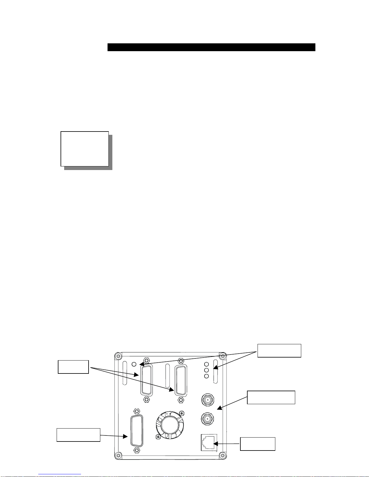
2.2 INPUT/OUTPUT ................................................................................................................................8
2.3 LED STATUS INDICATORS............................................................................................................... 9
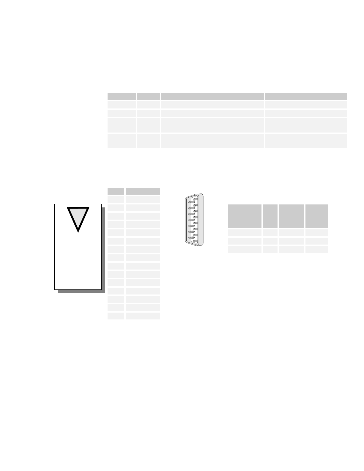
2.4 POWER INPUT .................................................................................................................................. 9
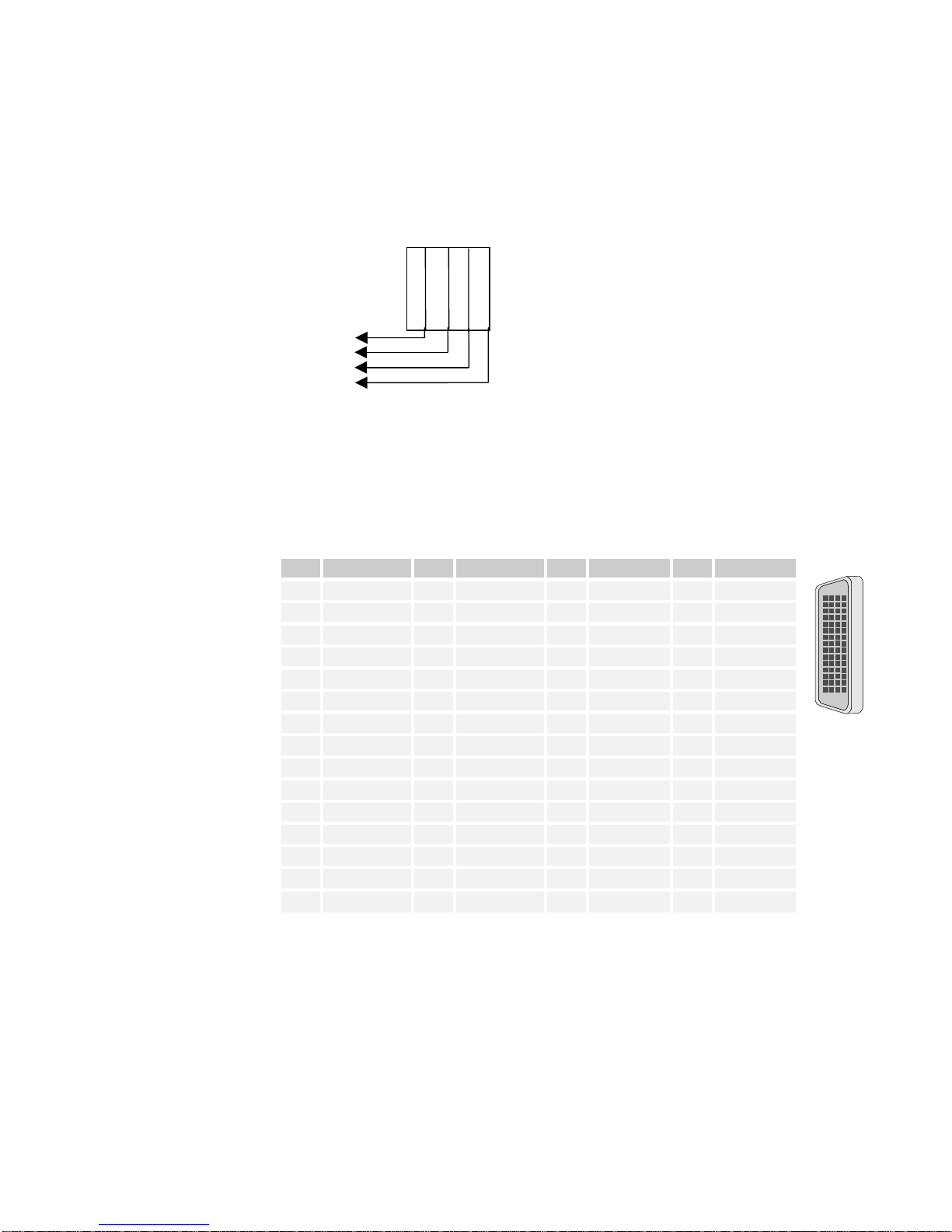
2.5 DATA OUTPUT............................................................................................................................... 10
Connector and Pinout........................................................................................................................... 10
Data Signals ......................................................................................................................................... 11
Data Clocking Signals.......................................................................................................................... 12
2.6 SERIAL COMMUNICATION ............................................................................................................. 12
Connector and Pinout........................................................................................................................... 12
Serial Communication Settings ............................................................................................................ 13
2.7 TTL TRIGGER INPUT AND OUTPUT ............................................................................................... 14
Connector ............................................................................................................................................. 14
2.8 INTEGRATION TIME ....................................................................................................................... 14
2.9 TIMING .......................................................................................................................................... 15
Programmed Integration ...................................................................................................................... 15
3.0 CAMERA OPERATION ............................................................................................................... 16
3.1 HOW TO CONTROL THE CAMERA................................................................................................... 16
Command Protocol Overview .............................................................................................................. 16
3.2 CONTROL REGISTER REFERENCE .................................................................................................. 17
3.3 READING THE CAMERA TYPE ........................................................................................................ 18
3.4 READING THE FIRMWARE REVISION.............................................................................................. 18
3.5 RESETTING THE CAMERA .............................................................................................................. 18
3.6 ADJUSTING GAIN........................................................................................................................... 19
3.7 ADJUSTING ANTI-BLOOMING ........................................................................................................ 19
3.8 CONTROLLING BINNING ................................................................................................................ 19
3.9 ADJUSTING USER OFFSET.............................................................................................................. 20
Reading Offset from the Camera .......................................................................................................... 21
3.10 TRIGGERING, INTEGRATION, AND FRAME RATE OVERVIEW ......................................................... 21
3.11 CONTROLLING INTEGRATION (SHUTTER TIME) ............................................................................. 22
Free Running (Programmed Integration): ........................................................................................... 23
Programmed Integration/SMA Trigger ................................................................................................ 23
Programmed Integration/Serial Trigger .............................................................................................. 24
External Integration/SMA Connector................................................................................................... 24
External Integration/Serial Connector ................................................................................................. 24
3.12 CONTROLLING FRAME RATE ......................................................................................................... 25
Free Running (Programmed Fame Rate) .............................................................................................25
External Trigger/SMA Connector......................................................................................................... 25
External Trigger/Serial Connector....................................................................................................... 25

1M60 Camera User’s Manual 4
DALSA C32-10010-01
4.0 OPTICAL AND MECHANICAL CONSIDERATIONS ............................................................ 26
4.1 MECHANICAL INTERFACE.............................................................................................................. 26
4.2 MECHANICAL TOLERANCES .......................................................................................................... 27
4.3 MOUNTING THE CAMERA .............................................................................................................. 27
5.0 CLEANING AND MAINTENANCE ........................................................................................... 28
5.1 CLEANING ..................................................................................................................................... 28
Electrostatic Discharge and the CCD Sensor ......................................................................................28
Preventing ESD Damage...................................................................................................................... 28
Protecting Against Dust, Oil, and Scratches ....................................................................................... 29
Cleaning the Sensor Window................................................................................................................ 29
5.2 MAINTENANCE .............................................................................................................................. 29
TROUBLESHOOTING............................................................................................................................. 30
7.0 WARRANTY .................................................................................................................................. 31
7.1 LIMITED ONE-YEAR WARRANTY .................................................................................................. 31
What We Do.......................................................................................................................................... 31
What is Not Covered............................................................................................................................. 31
How to Obtain Service for Your Equipment ......................................................................................... 31
8.0 INDEX ............................................................................................................................................. 32

1M60 Camera User’s Manual 5
DALSA C32-10010-01
CHAPTER 1
1.0 Introduction to the 1M60 Camera
1.1 Camera Highlights
Features
1024 x 1024 resolution, frame transfer
CCD architecture.
60 fps four outputs at full resolution,
20 MHz data rate
True 12-bit digitization
High sensitivity with low dark current
Progressive scan readout
On-chip shutter
Asynchronous image capture, externally triggerable to within 2 us.
Selectable binning up to 2 x 2
Programmable operation via RS232, including gain (1x and 4x), frame rate,
offset (-2047 to +2048), binning, and triggering.
100% fill factor
Description
The 1M60 digital camera provides high-sensitivity 12-bit images with 1k x 1k spatial
resolution at up to 60 frames per second (fps). The 1M60 is a frame transfer CCD
camera using a progressive scan CCD to simultaneously achieve outstanding
resolution and gray scale characteristics. A square pixel format and high fill factor
provide superior, quantifiable image quality even at low light levels.
Applications
The 1M60 is an outstanding performer in fast, very high resolution applications.
True 12 bit performance provides up to 4096 distinct gray levels—perfect for
applications with large interscene light variations. The low-noise, digitized video
signal also makes the camera an excellent choice where low contrast images must be
captured in challenging applications.

1M60 Camera User’s Manual 6
DALSA C32-10010-01
1.2 Image Sensor
Figure 1. Image Sensor Block Diagram Table 1. Sensor Structure
Sensor characteristics
ImageZone 14.34x14.34mm
Pixelsize 14µmx14µm
Activepixels 1024(H)x1024(V)
Totalnumberofpixels 1024(H)x1044(V)
DummyLines Top: 1 Bottom: 1
DarkReferenceLines Top:7 Bottom:6
IsolationLines Top: 3 Bottom: 3
InactiveLines Top: 0 Bottom: 1
Pre-scanElements (perZone) Left:17
Table 2. Sensor Cosmetic Specifications
Type Allowable
Blemishes WHITE
Vos=0.7 Vsat DARK
Vos=0.7Vsat In Darkness
(ref Vo:Average
Darkness Signal)
Columns 5α> 10% Vos |α|10% Vos α>5 mV
Clusters 10 α> 20% Vos |α|30% Vos α>10 mV
Pixels 100 α> 20% Vos |α|30% Vos α>10 mV
Blemish Definition
•Pixel: Maximum Blemish area of 2x2 pixels.
•Cluster: Less than 7 contiguous defects in a
column
•Column: More than 7 contiguous defects in a
column
•Defects measured in darkness at 25 °C
•Light Source: 2854 K with BG38 filter + F/3.5
optical aperture
•α: amplitude of video signal defect with
respect to mean output voltage Vos
1024 x 1024
Memory Area
1024 x 1024
Image Area
7 Dark Reference
3 Isolation
1024 Useful Pixels
3 Isolation
6 Dark Reference
1 Inactive
First
Pixel

1M60 Camera User’s Manual 7
DALSA C32-10010-01
1.3 Camera Performance Specifications
Table 3. 1M60 Camera Performance Specifications
Physical Characteristics Units
Resolution H x V pixels 1024 x 1024
Pixel Size µm 14 x 14
Pixel Fill Factor % 73.57
Size mm 94x94x102
Mass kg 0.85
Power Dissipation W< 17
Lens Mount F or C mount
Aperture mm 14.34x14.34
Regulatory Compliance Pending
Shock Immunity Pending
Vibration Immunity Pending
Operating Ranges Units Min. Max.
Frame Rate fps 7.5 110
Data Rate MHz 10 20
Data Format LVDS 12 bit
Responsivity DN/(nJ/cm2)11@540 nm
Operating Temp °C 10 45
+15 Input Voltage V+14.925 +15.075
+5 Input Voltage V+4.975 +5.025
-5 Input Voltage V- 4.975 - 5.025
Nominal Gain Range 1x 4x
Calibration Conditions Units Setting Min. Max.
Data Rate MHz 20 20 20
Frame Rate Hz 2.75
+15 Input Voltage V+15 +14.925 +15.075
+5 Input Voltage V+5 +4.975 +5.025
-5 Input Voltage V- 5 - 4.975 - 5.025
Ambient Temperature °C 25
Binning 1x1
Gain X 1
Electro-Optical Specifications Units Min. Typical Max.
Dynamic Range dB 68.5
Pixel Response Non-Uniformity %rms 2.5 3.0
System Noise DN(rms) 1.0 1.2
Notes:

1M60 Camera User’s Manual 8
DALSA C32-10010-01
CHAPTER 2
2.0 Camera Hardware Interface
2.1 Installation Overview
In order to set up your camera, you should take these initial steps:
1. Power down all equipment.
2. Following the manufacturer’s instructions, install the frame grabber (if
applicable). Be sure to observe all static precautions.
3. Install any necessary imaging software.
4. Before connecting power to the camera, test all power supplies. Ensure that all
the correct voltages are present at the camera end of the power cable (the Camera
Performance Specifications earlier in this document list appropriate
voltages). Power supplies must meet the requirements defined in section 2.4
Power Input.
5. Inspect all cables and connectors prior to installation. Do not use damaged
cables or connectors or the camera may be damaged.
6. Connect data, serial interface, and power cables.
7. After connecting cables, apply power to the camera. The POST (power on
self test) LED on the back of the camera should glow green after one second
to indicate that the camera is operating and ready to receive commands.
2.2 Input/Output
The camera provides 12-bit LVDS data and synchronization signals through the
data output connectors. Camera functions such as frame rate, integration time,
binning, camera gain and offset are all controllable by the user via RS232 serial
port. The camera is capable of free running operation or may be triggered
externally via the input TRIGGER IN. TRIGGER OUT allows the
synchronization of shutters or illumination sources in free running or externally
triggered modes.
Figure 2. Camera Inputs/Outputs
Thisinstallationoverview
assumesyouhave not
installedanysystem
componentsyet.
Serialport
Dataoutputs
Powersupplyinput
LEDStatusindicators
Triggerinput&output
P
O
W
E
R
POST
BIN
MODE
IN
OUT
T
R
I
G
G
E
R
S
E
R
I
A
L
S/N_______________
D
A
T
A
ON D
A
T
A
21

1M60 Camera User’s Manual 9
DALSA C32-10010-01
2.3 LED Status Indicators
There are four LED’s visible on the rear cover of the camera that indicate the status
of the camera.
Table 4. LED Functions
LED Label Color LED “ON” LED “OFF”
ON Green Camera is receiving power There is no camera power
POST Green Camera Power On Self Test successful Camera failed Power On Self Test
BIN Red Camera is operating in a binning mode Camera is operating unbinned
(1x1)
MODE Red Camera is in an external triggermode (uses
external signal to trigger image capture) Camera is triggering image
capture internally
2.4 Power Input
Table 5. Power Connector Pinout
Pin Symbol
1+5V The camera has the following input power
requirements.
2+5V
3- 5V
4+15V
V
(DC)
±%Max
Ripple
mV
A
5NC +15 0.5 < 5 0.45
6NC +5 0.5 < 5 1.88
7GND -5 0.5 < 5 0.58
8GND
9+5V
10 - 5V
11 +15V
12 NC
13 NC
14 GND
15 GND
1
9
15 8
DB15M
(AMP Part # 747236-4
or equivalent)
Note: Performance specifications are not
guaranteed if your power supply does not
meet these requirements.
Many high quality supplies are available
from other vendors. DALSA assumes no
responsibility for the use of these supplies.
When setting up the camera’s power supplies, follow these guidelines:
•Do not connect or disconnect cable while power is on.
•Do not use the shield on a multi-conductor cable for ground.
•Keep leads as short as possible to reduce voltage drop.
•Use high-quality linear supplies to minimize noise.
!
WARNING:Itis
extremelyimportant
thatyouapplythe
appropriatevoltagesto
yourcamera.Incorrect
voltageswilldamage
thecamera.

1M60 Camera User’s Manual 10
DALSA C32-10010-01
2.5 Data Output
Data channel outputs represent the CCD per the following (Image viewed from the
front of the CCD).
The camera back panel output connectors DATA1 and DATA2 utilize differential
LVDS signals with pin assignments as follows:
Connector and Pinout
Table 6. DATA1 Connector Pinout
Pin Symbol Pin Symbol Pin Symbol Pin Symbol
1DA0+ 16 Reserved 31 DB8- 46 GND
2DA0- 17 DA7+ 32 DB8+ 47 DB11-
3DA1+ 18 DA7- 33 DB7- 48 DB11+
4DA1- 19 DA8+ 34 DB7+ 49 DB10-
5DA2+ 20 DA8- 35 DB6- 50 DB10+
6DA2- 21 DA9+ 36 DB6+ 51 DB9-
7DA3+ 22 DA9- 37 DB5- 52 DB9+
8DA3- 23 DA10+ 38 DB5+ 53 Reserved
9DA4+ 24 DA10- 39 DB4- 54 Reserved
10 DA4- 25 DA11+ 40 DB4+ 55 VSYNC-
11 DA5+ 26 DA11- 41 DB3- 56 VSYNC+
12 DA5- 27 DB0+ 42 DB3+ 57 HSYNC-
13 DA6+ 28 DB0- 43 DB2- 58 HSYNC+
14 DA6- 29 DB1+ 44 DB2+ 59 PIXCLK-
15 Reserved 30 DB1- 45 GND 60 PIXCLK+
15
1
16
30
45
31
46
60
(Molex Part #
70928-2000
or equivalent)
NC = No Connect. These pins are unused.
ABCD

1M60 Camera User’s Manual 11
DALSA C32-10010-01
!
Table 7. DATA2 Connector Pinout
Pin Symbol Pin Symbol Pin Symbol Pin Symbol
1DC0+ 16 Reserved 31 DD8- 46 GND
2DC0- 17 DC7+ 32 DD8+ 47 DD11-
3DC1+ 18 DC7- 33 DD7- 48 DD11+
4DC1- 19 DC8+ 34 DD7+ 49 DD10-
5DC2+ 20 DC8- 35 DD6- 50 DD10+
6DC2- 21 DC9+ 36 DD6+ 51 DD9-
7DC3+ 22 DC9- 37 DD5- 52 DD9+
8DC3- 23 DC10+ 38 DD5+ 53 Reserved
9DC4+ 24 DC10- 39 DD4- 54 Reserved
10 DC4- 25 DC11+ 40 DD4+ 55 VSYNC-
11 DC5+ 26 DC11- 41 DD3- 56 VSYNC+
12 DC5- 27 DD0+ 42 DD3+ 57 HSYNC-
13 DC6+ 28 DD0- 43 DD2- 58 HSYNC+
14 DC6- 29 DD1+ 44 DD2+ 59 PIXCLK-
15 Reserved 30 DD1- 45 GND 60 PIXCLK+
15
1
16
30
45
31
46
60
(Molex Part #
70928-2000
or equivalent)
WARNING. Care must be taken when connecting Data cables to the camera to insure
proper connection and to prevent damage to the connector.
Data Signals
Table 8. Data Signal Definition
Signal Description
D*0+, D*0- Data bit 0 true and complement--Output. (Least significant bit)
D*1+, D*1- Data bit 1 true and complement--Output.
D*2+, D*2- Data bit 2 true and complement--Output.
D*3-D*10+,- etc. Etc.
D*11+, D*11- Data bit 11 true and complement--Output. (Most significant bit)
Digitized video data is output from the camera as LVDS differential signals using
two Molex 60-pin connectors on the rear panel (labeled “DATA1” and “DATA2”).
The data is synchronous and is accompanied by a pixel clock and clocking signals.
Note: Data frequency is dependent on binning mode. Reference section 3.10 –
Triggering, Integration, and Frame Rate Overview.
IMPORTANT:
Thiscamerausesthe
falling
edgeof the
pixelclocktoregister
data.

1M60 Camera User’s Manual 12
DALSA C32-10010-01
RJ-11
View into female jack
6-position with 4 conductors
RXDTXDGND
Data Clocking Signals
Table 9. Clock Signal Descriptions
Signal Description
PIXCLK+, PIXCLK- Pixel clock true and complement. 20MHz (unbinned) -- Output.
Data is valid on the falling edge. Note that data and PIXCLK frequency is
dependent on binning mode. Reference section 3.10 – Triggering,
Integration, and Frame Rate Overview
HSYNC+, HSYNC- Horizontal sync, true andcomplement--Output.
HSYNC high indicates the camera is outputting a valid line of data. The
number of valid lines in a frame depends on binning mode. Reference section
3.10 – Triggering, Integration,and Frame Rate Overview.
VSYNC+, VSYNC- Vertical sync, true and complement--Output.
VSYNC high indicates the camera isoutputting a valid frame of data.
2.6 Serial Communication
Connector and Pinout
The serial interface provides control of frame rate, integration time (shuttering),
video gain and offset, pixel binning, external trigger and external integration (for
information on how to control these functions, see “Operating the Camera” later in
this document). The remote interface consists of a two-wire (plus ground) full duplex
RS-232 compatible serial link, used for camera configuration, and two back panel
SMA coax connectors used for external trigger input and output
The camera uses an RJ-11 telephone-style connector for
serial communications, with four conductors installed in a
six-position connector. Note that both four- and six-
conductor plugs may be used interchangeably with the RJ-
11 jack.
IMPORTANT: Both the PC/AT and the camera are configured
as “DTE” (Data Terminal Equipment) devices requiring the
TXD and RXD lines to be swapped when interconnecting
the two (note that pin 4, normally the yellow wire, is not
used on the RJ-11.) That is, the TXD pin represents DATA
OUT and the RXD pin represents DATA IN on both devices, so that one device’s
TXD line must connect to the other device’s RXD line and vice-versa.

1M60 Camera User’s Manual 13
DALSA C32-10010-01
!
Serial Port Configuration
Baud 9600, fixed
Start bits 1
Data bits 8
Stop bits 1
Parity None
Figure 3. 25 Pin Serial Port Connector to Camera RJ-11 Connector
Figure 4. 9 Pin Serial Port Connector to Camera RJ-11 Connector
Serial Communication Settings
The serial interface operates at RS-232 levels with fixed
parameters of 9600 baud, 1 start bit, 8 data bits, 1 stop bit,
and no parity. The interface uses only three wires, for
received data, transmitted data, and ground. In general
writing data must start with a write command byte and be
followed by a data byte. Reading a camera register
requires only a single read command byte.
WARNING: Due to initialization sequencing after power-up, no commands should be
sent to the camera for a minimum of 1 second after power up.

1M60 Camera User’s Manual 14
DALSA C32-10010-01
Serial Cable Source
The remote interface connector, on the cameras rear panel, is
specified as a low-profile RJ-11 modular connector. The connector
is a 6-position model, but only the center four positions are
populated with contacts. It will mate with either the 4-position or 6-
position cable plugs. This type of connector typically requires
special assembly tools; complete cable assemblies are available from
suppliers such as Digi-Key:
Digi-Key
701 Brooks Ave. South
Thief River Falls, MN 56701
1-800-344-4539
cable part number:
H2643-14-ND (14 feet)
DALSA provides serial cables in 3 lengths: 10’, 20’ and 50’. Part number CL-31-00004-xx (where xx
refers to the cable length in feet).
2.7 TTL Trigger Input and Output
Connector
The camera uses an SMA connector (labeled TRIGGER IN) to allow the user to
provide a standard TTL signal to control camera integration and readout. The input is
high impedance (>10K) allowing the user to terminate at the SMA input as needed.
The camera has another SMA connector (TRIGGER OUT) that provides a standard
TTL output which is high whenever the camera is integrating.
Figure 5. Trigger Timing Description
2.8 Integration Time
The minimum integration time (or shutter time) is 5 µs. As with any full frame
imager, the camera will continue to integrate during read out unless externally
shuttered or strobed.
TTL Trigger Input
Integration
1.5 us
+/- 0.5
Min. 5 µs

1M60 Camera User’s Manual 15
DALSA C32-10010-01
2.9 Timing
Programmed Integration
The 1M60 pixel clock runs at 20 MHz, so each pixel clock cycle will be 1/20,000,000 or
50 ns. The following diagram and tables describe the correct timing requirements for the
1M60 camera.
Figure 6. 1M60 Timing
“A” represents the number of falling clock edges from the rising edge of VSYNC to the
rising edge of HSYNC.
“B” represents the number of falling clock edges prior to the first word. (Pre-Scan
pixels)
“C” represents the number of words per line.
“D” represents the number of falling clock edges between the last word and the falling
edge of HSYNC. (Post-Scan pixels)
“E” represents the number of falling clock edges between a falling HSYNC and a
rising HSYNC.
“F” represents the number of falling clock edges from the falling edge of HSYNC to
the falling edge of VSYNC
Table 10. HSYNC Pixel Timing
Horizontal
Binning
Mode
A B C D E F
1x 68 14 256 224 2
2x 42 12 128 115 1
Table 11. VSYNC Pixel Timing (HSYNC falling edges/VSYNC falling edge)
Vertical
Binning
Mode
Pre-Scan
Lines/Frame Active
Lines/Frame Post Scan
Lines/Frame
1x 10 1024 10
2x 5512 5
V
SYNC
Data
HSYNC
PIXEL
CLOCK
123
A
BCCE
DF
IMPORTANT:
This camera uses
the falling edge of
the pixel clock to
register data.

1M60 Camera User’s Manual 16
DALSA C32-10010-01
!
Serial Port Configuration
Baud 9600, fixed
Start bits 1
Data bits 8
Stop bits 1
Parity None
CHAPTER 3
3.0 Camera Operation
3.1 How to Control the Camera
The 1M60’s RS-232-compatible serial interface allows you to control its
configuration and operation, including:
Triggering Mode
Binning
Integration Time
Gain
Offset
Command Protocol Overview
The camera accepts 8-bit command/value pairs via its RJ-
11 serial port using RS-232 compatible signals. Camera
commands are “clock” commands which apply to the
electronics that drive the image sensor. These include
clock generation, frame rate, integration time, and
binning. Each set of commands includes read and write
variants. With the exception of reset commands, all 8-bit
write commands must be followed by an 8-bit data byte.
The commands are interpreted as follows:
WARNING: Any commands not listed should be considered invalid. Writing to invalid
addresses may overwrite camera calibration information, requiring the camera to be
returned for recalibration.
WARNING: Due to initialization sequencing after power-up, no commands should be sent to
the camera for a minimum of 1 second after power up.

1M60 Camera User’s Manual 17
DALSA C32-10010-01
3.2 Control Register Reference
A number of functions and modes depend on the control register settings. These
settings are detailed in the following sections.
The “Write Control Register” command is used to write a register that controls
specific camera triggering and test functions. This command must be followed by a
data byte with bits defined as shown in the following table.
The “Read Control Register” command allows interrogation of the camera to
determine current configuration of the control register.
Table 12. Control Register Bit Definitions
Register Write
Command Read
Command Bit Function Default
Reset 80h 7:0 Resets all registers to default values NA
Camera Type NA C3h 7:0 Read camera type 02h
Firmware Rev NA C5h 7:0 Read firmware revision NA
7Integration Mode
0=Internal
1=External
0
6Video Gain
0=1x
1=4x
0
5Anti-Blooming
0 = Anti-Blooming Enabled
1 = Anti-Blooming Disabled
0
4Binning Mode
0 = 1x1
1 = 2x2
0
3Trigger Mode
0=Internal
1=External
00
Register 1 82h C2h
2:0 Shutter Control
000 = None (Frame Rate Controlled)
100 = 8 ms (1/125)
101 = 4 ms (1/250)
110 = 2 ms (1/500)
111 = 1 ms (1/1000)
000
Register 2 84h C4h 7:0 User Offset MS Byte (Bits 11-4 of 12 bits) 00h
7Serial Trigger (If Integrate mode=1) 0
6:4 Frame Rate
000 = 60 fps
001 = 30 fps
010 = 15 fps
011 = 7.5 fps
100 = 110 fps (2x2 binninf only)
000
Register 3 88h C8h
3:0 Pixel Offset LS nibble 000

1M60 Camera User’s Manual 18
DALSA C32-10010-01
3.3 Reading the Camera Type
This read command returns an 8-bit value unique to the type of camera interrogated.
A 1M60 will return a value of 02h when this command is issued. This is useful for
applications that need to function with multiple DALSTAR camera types.
Example: Read the camera type
Command Value Returned (1M60)
Binary 1100 0011 0000 0010
Hex C3h 02h
3.4 Reading the Firmware Revision
This command returns a byte in which the lower nibble is the revision number for the
clock board firmware and the upper nibble is undefined. The ability to read this
value may assist in customer support issues.
Example: Read the firmware version
Command
Binary 1100 0101
Hex C5h
3.5 Resetting the Camera
This is the only “write” command that is not followed by a data byte. This command
resets all clock board registers to their default values (the values used at power-up).
Table 13. Default values in effect after reset
Feature 1M60 Default
Frame Rate (fps) 60
Integration Time (ms) 15.8
Resolution (pixels) 1024 x 1024
Video Gain 1x
Binning Mode 1x1
Pixel Offset 0
Triggering INTERNAL
Integration Control INTERNAL
Data Rate (MHz) 20
Example
Use this command to reset the camera:
Command Value
Binary 1000 0000 -
Hex 80h -

1M60 Camera User’s Manual 19
DALSA C32-10010-01
3.6 Adjusting Gain
Bit [6] of register 1 is the Video Gain control bit. When this bit=0 the video channel
gain=1x. When this bit =1, the video channel gain=4x.
Example
Use this command to set the gain to 4x:
Command Value
Binary 10000010 *1** ****
Hex 82h **h
Note: The register containing the Gain bit also controls other configuration data. All
bits must be set appropriately.
Note: At any gain setting, the CCD imager is still subject to blooming when it is over
illuminated. To remedy over illumination, reduce the integration time or select a
higher f-stop value
3.7 Adjusting Anti-Blooming
Bit [5] of register 1 is the Anti-Blooming control bit. When this bit=0 anti-blooming
is enabled. When this bit = 1, anti-blooming is disabled.
Example
Use this command to disable Anti-Blooming
Command Value
Binary 10000010 **1*****
Hex 82h **h
Note: The register containing the Anti-Blooming bit also contains other
configuration data. All bits (*) must be set appropriately.
Note: At any gain setting, the CCD imager is still subject to blooming when it is over
illuminated. To remedy over illumination, reduce the integration time or select a
higher f-stop value
3.8 Controlling Binning
Binning increases the camera’s light sensitivity by decreasing horizontal and vertical
resolution—the charge collected by adjacent pixels is added together.

1M60 Camera User’s Manual 20
DALSA C32-10010-01
Example: 2x2 Binning
Charge in
4 ad
j
acent
p
ixels
More charge
=
brighter pixel
Charge binned:
1
p
ixel out
p
ut
Normal image Binned image
2
q1
q1
+
q2
+
q3
+
q4
q3
q2
q4
1
aa
The 1M60 is capable of 2x2 binning. Bit [4] of register 1 is the Binning control bit.
When this bit=0 the camera is in standard 1x1 mode. When this bit = 1, the camera
will operate with 2x2 binning.
Example: Setting the camera to 2x2 binning mode
Command Value
Binary 1000 0010 **** 1***
Hex 82h **h
Note: When the camera is in 2x2 binning mode, the BIN LED on the right side of
the rear cover will be illuminated.
Note: The register containing the Binning bit also contains other configuration data.
All bits (*) must be set appropriately.
3.9 Adjusting User Offset
User offset is adjustable from -2047 to +20478 by a 12 bit value as an MS and LS
byte. The offset data is only written when the most-significant 8 bits are written to
the MS Offset register. Therefore, the lower 4 bits should be written first to the LS
Offset register, followed by the upper 8 bits, which will cause the offset to be applied
to the pixel output.
The pixel offset data is written as a 2’s compliment number. Therefore either
positive or negative offsets can be added to the pixel output to enhance the image
contrast.
The offset value that is programmed effects the pixel offset by a ratio of about 8 to 5.
So, for that example, if an offset value of a positive 16 is entered to registers 2 and
3 the resulting pixel data will be adjusted by a positive 10.
This manual suits for next models
2
Table of contents
Other Dalstar Security Camera manuals