Axis 225FD User manual

AXIS 225FD
Network Camera
Installation Guide
ENGLISH DEUTSCH FRANCAIS ESPAÑOL ITALIANO
Installation instructions are also available in German, French, Spanish and Italian in this manual


AXIS 225FD Installation Guide Page 3
AXIS 225FD
Fixed Dome Network Camera
Installation Guide
This installation guide provides instructions for installing the AXIS 225FD
Fixed Dome Network Camera on your network. For all other aspects of using
the product, please see the AXIS 225FD User’s Manual, available from
www.axis.com or on the Axis Installation CD.
Installation steps
1. Check the package contents against the list below.
2. Install the hardware - page 4.
3. Connect the cables - page 4.
4. Set the IP address - page 7.
5. Set the password - page 12.
6. Adjust the image - page 14.
Package contents
Item Title/Variants
Fixed Dome Network Camera AXIS 225FD
Indoor Power Adapter
Note: The power adapter is country spe-
cific, please check that the type of power
adapter you are using is correct
Europe
UK
Australia
USA/Japan
Korea
Mounting kit Allen key for tamper-proof screws
3 screws and plugs for solid walls
Drill template
Documentation AXIS 225FD Installation Guide
Axis Installation CD
Warranty Document
Important!
This product must be installed in
compliance with local laws and
regulations.
ENGLISH

Page 4 AXIS 225FD Installation Guide
Installing the hardware
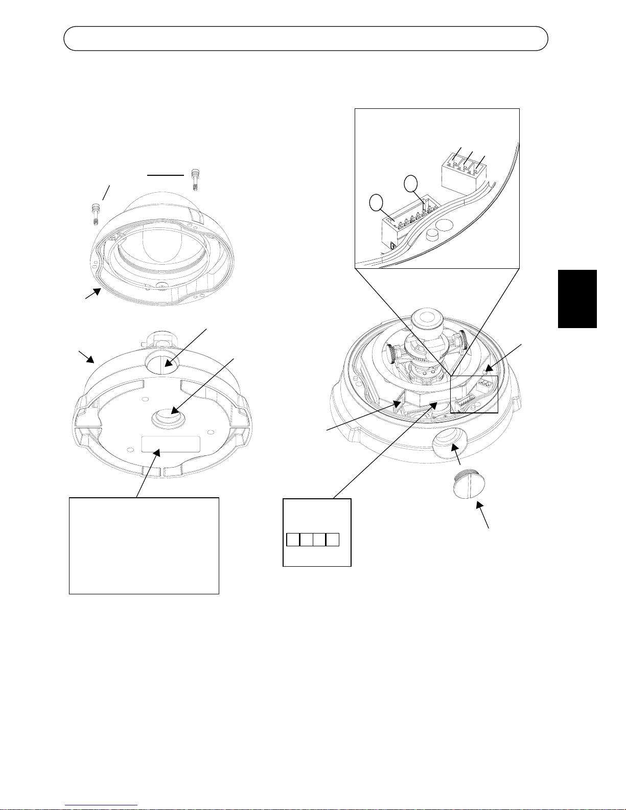
Refer to the illustration on page 5 for a detailed overview of the AXIS 225FD.
1. Make a note of the serial number (S/N) which is located on the product
label on the base of the unit casing. The serial number is used in the
installation.
2. Loosen the tamper-proof screws using the supplied allen key and lift the
dome casing from the unit casing. Be careful not to damage the dome or
scratch the glass.
3. Using the drill template, drill three holes in the ceiling/wall. The side
conduit hole must face downwards if the camera is installed vertically.
4. Route the network and power cables through the conduit hole on the side
or bottom of the casing depending on the installation.
5. Install the unit casing onto the ceiling/wall using the supplied screws and
plugs. Seal the holes with silicon sealant to prevent moisture from
leaking in to the casing.
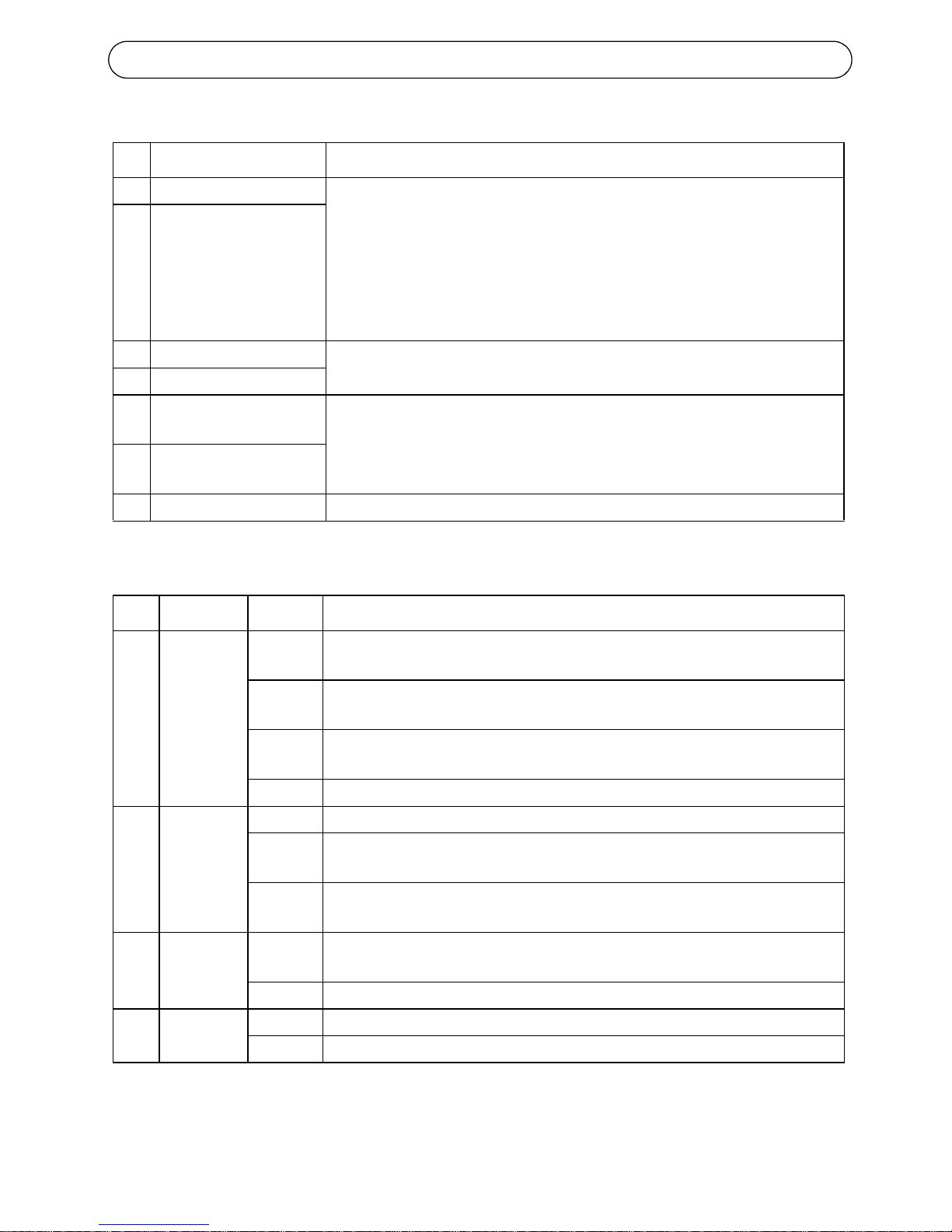
Connecting the cables
1. Connect the network cable to the camera’s network connector.
2. Connect power to the power connector block, using one of the methods
listed below:
• PoE (Power over Ethernet) via the network cable. This will automatically be
detected if available via the network. Note that PoE provides power for
the camera only (not the heater).
• Connect the supplied indoor power adapter to the power connector block in
the camera casing. Note that this indoor power adapter provides power
for the camera only (not the heater).
• Connect an outdoor power supply to the power connector block in the
camera casing. For information on available outdoor power supplies, please
visit the Support pages at http://www.axis.com/techsup/
3. Check that the network, status and power LEDs light up green. If you
intend to use the heater, check that the heater LED lights up green. See
table on page 6 for LED descriptions.
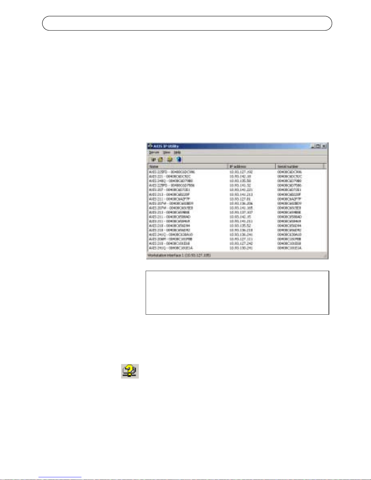
4. Refer to “Setting the IP address” on page 7 for information on how to
assign an IP address to the AXIS 225FD.

AXIS 225FD Installation Guide Page 5
Description
Notes:• Use cables, cable glands and conduits that are suitable for the installation and that are in
compliance with the IP66 rated, outdoor-proof, vandal resistant design of the AXIS 225FD.
• Conduit dimensions: NTP 3/4" -14 (Pipe thread).
• Use silicon sealant on both the conduit and the plug to prevent moisture from leaking into
the casing.
Conduit hole
Conduit hole
Network
connector
Serial number (S/N)
Control
Conduit hole
and plug
LED
indicators
(see table 2)
1234
Please make a note of the
The serial number is required
during the installation.
serial number and retain
for future reference.
1
7
button
Power connector block
(see table 1)
I/O terminal
block
GND
+orAC
AC
(side)
(bottom)
Tamper-proof
screws
Unit casing
Dome casing
ENGLISH

Page 6 AXIS 225FD Installation Guide
Table 1 - I/O terminal connector block:
Table 2 - LED indicators:
Pin Function Description
1Output A On the external device output terminals (A and B), there is no distinc-
tion between positive and negative (+ and -). The terminals use a pho-
tocoupler and are electrically isolated from the other internal
circuitry.
The maximum load should not exceed 100mA and the maximum volt-
age should be not more than 50V DC. Note: Connecting AC to the out-
put will damage the unit.
2Output B
3Digital Input 1 Connect to GND to activate, or leave floating (or unconnected) to
deactivate.
4Digital Input 2
5RS-485/422-A
(non-inverting) A half-duplex RS-485/422 interface for controlling auxiliary equip-
ment.
6RS-485/422-B
(inverting)
7GND Ground.
LED Function Color Description
1Network Green Steady for connection to 100 Mbit/s network. Flashes for network
activity.
Amber Steady for connection to 10 Mbit/s network. Flashes for network activ-
ity.
Red Flashes rapid red, together with the Status indicator, for hardware
error.
Unlit No connection.
2Status Green Shows steady green for normal operation.
Amber Shows steady amber during reset to factory default or when restoring
settings.
Red Slow flash for failed upgrade. Rapid flash, together with the Network
indicator, for hardware error.
3Heater Green Steady green when the power connected is sufficient for the heater
i.e. (12V DC min 20W or 24V AC min 25VA)
Red Insufficient power for the heater.
4Power Green Normal operation.
Amber Flashes green/amber during firmware upgrade.

AXIS 225FD Installation Guide Page 7
Setting the IP address
The AXIS 225FD is designed for use on an Ethernet network and must be
assigned an IP address to make it accessible.
AXIS IP Utility
All installation methods
This table shows all of the available methods for setting or discovering the IP
address. Select a method from the left-hand column and check the
requirements for it to the right.
Notes: •UPnP™ and DHCP are both enabled by default in the AXIS 225FD.
• The AXIS 225FD has the default IP address 192.168.0.90
• To view the admin pages for the DHCP server, please see the server’s own
documentation. You may need to contact your network administrator.
• If setting the IP address fails, check that there is no firewall blocking the operation.
•AXIS Dynamic DNS Service requires an Internet connection without HTTP proxy.
•Bonjour - applicable only in browsers with support for Bonjour e.g. Safari.
AXIS IP Utility is the recommended method for setting an IP address in Windows. This free appli-
cation can be used on networks with or without a DHCP server. See page 7 for more information.
DHCP Server
in network
Install on
same network
segment
Operating system
AXIS IP Utility
(recommended method)
See page 8
Optional Required Windows
UPnP™
See page 9 Optional Required Windows (ME or XP)
Bonjour
See page 9 Optional Required Mac OSX (10.4 or later)
ARP/Ping
See page 10 Required All
AXIS Dynamic DNS Service
See page 11 Recommended All
View DHCP server
admin pages for IP address
(See note below)
Required All
Requirements
methods
Installation
ENGLISH

Page 8 AXIS 225FD Installation Guide
AXIS IP Utility
AXIS IP Utility is a free Windows application that discovers and displays
Axis devices on your network. The application can also be used to manually
set a static IP address. AXIS IP Utility is available on the CD supplied with
this product, or it can be downloaded from www.axis.com/techsup
Note that you must install the AXIS 225FD on the same network segment
(physical subnet) as the computer running AXIS IP Utility.
Automatic discovery
1. Check that the AXIS
225FD is connected
to the network and
that power has been
applied.
2. Start AXIS IP Utility.
When the AXIS
225FD appears in the
window, double-click
it to open the
camera’s home page.
3. See page 12 for
instructions on how
to set the password.
Set the IP address manually
1. Acquire an unused IP address on the same network segment your com-
puter is connected to.
2. Click the button Set IP address using serial number and enter the
serial number and IP address for the AXIS 225FD. The serial number is
located on the product label.
3. Click the Set IP button and follow the instructions.
4. Click View Home Page to access the AXIS 225FD web pages.
5. See page 12 for instructions on how to set the password.
Notes:
Set the IP address using IP Utility within 2 minutes of starting
the camera.
AXIS IP Utility can be used to change a dynamically set
IP address to a static one.

AXIS 225FD Installation Guide Page 9
UPnP™
UPnP™ functionality is enabled by default in the AXIS 225FD. If also enabled
on your computer (Windows ME or XP), the camera will automatically be
detected and a new icon will be added to “My Network Places.” Click this
icon to access the AXIS 225FD. See also page 12 for instructions on how to
set the password.
Note:
Bonjour
Bonjour (Mac OSX) will automatically discover the AXIS 225FD once it is
connected to the network. Simply navigate to the Bonjour bookmark in your
browser (e.g. Safari) and click on the camera’s link to access the Web pages.
See page 12 for instructions on how to set the password.
To install the UPnP™ service on your computer, open the Control Panel from the Start Menu and
select Add/Remove Programs. Select Add/Remove Windows Components and open the
Networking Services section. Click Details and then select UPnP as the service to add.
UPnP™ is a certification mark of the UPnP™ Implementers Corporation.
ENGLISH

Page 10 AXIS 225FD Installation Guide
Manual Installation with ARP/Ping
1. Acquire an IP address on the same network segment your computer is
connected to.
2. Locate the serial number (S/N) on the AXIS 225FD product label.
3. Open a Command Prompt on your computer and enter the following
commands (appropriate for your operating system):
4. Check that the network cable is connected to the camera. Start/restart the
camera by disconnecting and reconnecting power.
5. Close the Command prompt when you see ‘Reply from 192.168.0.125: ...’
or similar.
6. Start your browser, type in http://<IP address> in the Location/Address
field and press Enter on your keyboard.
7. See page 12 for instructions on how to set the password.
Notes: • The ARP/Ping command must be issued within 2 minutes of connecting power to the
camera.
• To open a command prompt in Windows: from the Start menu, select Run... and type cmd
(or command in Windows 98/ME). Click OK.
• To use the ARP command on a Mac OS X, use the Terminal utility, which is found under
Application > Utilities.
Windows syntax:
arp -s <IP Address> <Serial Number>
ping -l 408 -t <IP Address>
Windows example:
arp -s 192.168.0.125 00-40-8c-18-10-00
ping -l 408 -t 192.168.0.125
UNIX/Linux/Mac syntax:
arp -s <IP Address> <Serial Number> temp
ping -s 408 <IP Address>
UNIX/Linux/Mac example:
arp -s 192.168.0.125 00:40:8c:18:10:00 temp
ping -s 408 192.168.0.125

AXIS 225FD Installation Guide Page 11
The AXIS Internet Dynamic DNS Service
The AXIS Internet Dynamic DNS Service is a free service provided by Axis,
which allows you to quickly and simply install your camera. More
information about the AXIS Internet Dynamic DNS Service is available at
www.axiscam.net
To perform this procedure, your network should have an Internet connection
with no HTTP proxy, and IP addresses should preferably be assigned via
DHCP.
1. Check that the AXIS 225FD is connected to the network and that power
has been applied.
2. Wait for the Power indicator on the AXIS 225FD to show a steady green,
whereupon it will have received a dynamic IP address from a DHCP
server on your network.
3. Wait 60 seconds and push the control button on the camera once. The
Power indicator will blink amber while it connects to the AXIS Internet
Dynamic DNS service. When the registration process is complete, the
indicator will return to steady green.
4. To complete the installation, visit www.axiscam.net from an Internet
connected computer. This must be done within 60 minutes of pressing
the Control button.
5. Follow the on-screen instructions provided by the AXIS Internet
Dynamic DNS Service. You will need the product’s serial number to
complete the installation. The serial number is located on the product
label. See also page 12 for instructions on how to set the password.
Important!
To remove the DNS name and unregister from this service, open the Setup
pages in the AXIS 225FD, click System Options > Network > TCP/IP >
Basic, click the Settings button for the AXIS Internet Dynamic DNS Service
and finally, click the Remove button.
Please note that this procedure will send the IP address, firmware version, product type
and serial number of the AXIS 225FD to the AXIS Internet Dynamic DNS Service. No
personal information is transferred.
ENGLISH

Page 12 AXIS 225FD Installation Guide
Setting the Password
1. When accessing the AXIS
225FD for the first time, the
‘Configure Root Password’ dia-
log will be displayed on the
screen.
2. Enter a password and then re-
enter it, to confirm the spelling.
Click OK.
3. The ‘Enter Network Password’ dialog will appear. Enter the User name:
root
Note: The default administrator user name root is permanent and cannot
be deleted.
4. Enter the password as set in step 2 above, and click OK. If the password
is lost, the AXIS 225FD must be reset to the factory default settings. See
page 16.
5. If required, click Yes to install AMC (AXIS Media Control), to allow
viewing of the video stream in your browser. You will need administrator
rights on the computer to do this.
6. The Live View page of the AXIS 225FD is displayed, complete with links
to the Setup tools, which allow you to customize the camera to your
specific needs.
7. Proceed to “Adjusting the image” on page 14 to set the focus and zoom
and complete the hardware installation.

AXIS 225FD Installation Guide Page 13
Setup - Provides all the
necessary tools for config
-
uring the camera to suit
your requirements.
Help - Displays online hel
p
on all aspects of using the
camera.
ENGLISH

Page 14 AXIS 225FD Installation Guide
Adjusting the image
1. Open the Live View page in the Web interface and make the following
adjustments:
2. Loosen the pan adjustment ring and tilt adjustment screws. Hold the lens
while turning the pan adjustment ring, otherwise the lens may rotate
with the lock ring and damage or disconnect the cable.
3. Turn the lens to the desired direction. Do not turn the lens more than
360° as this may cause the internal cables to disconnect.
4. Once satisfied, gently tighten the pan adjustment ring and tilt adjustment
screws to secure the camera’s position.
5. Turn the image balance ring to set the image to the correct angle.
6. Loosen the zoom puller counterclockwise, rotate the zoom ring and
determine the desired zoom position.
Pan adjustment ring
Image
Zoom
Focus puller
Tilt
screw
3 tamper-proof
screws
Unit casing
Dome casing
balance
ring
adjustment
Tilt
screw
adjustment
puller

AXIS 225FD Installation Guide Page 15
7. Go to the Basic Configuration menu in the Web interface and select
Focus. Follow the on-screen instructions to set the focus.
8. After determining the zoom and focus, lock the zoom puller and the
focus puller in position by rotating the screws clockwise.
Note:
Completing the installation
1. Check that the safety cord is attached to the hook to prevent the dome
casing from falling off the unit casing during the installation process. Be
careful not to damage the dome or scratch the glass.
2. Rotate the black protective shield inside the dome to match the camera’s
position.
3. Clean the dome with a dry soft cloth to remove dust and finger prints
and use a blower to remove dust from the lens.
4. Replace the dome casing and tighten the tamper-proof screws using the
allen key. The installation is now complete.
The image can be fine-tuned for low lighting conditions.
Go to 'Setup > Video & Image > Advanced' and refer to the help files for more information.
ENGLISH

Page 16 AXIS 225FD Installation Guide
Accessing the AXIS 225FD from the Internet
Once installed, your AXIS 225FD is accessible on your local network (LAN).
To access the camera from the Internet, network routers must be configured
to allow incoming traffic, which is usually done on a specific port. Please
refer to the documentation for your router for further instructions.
For more information on this and other topics, please visit the Axis Support
Web at www.axis.com/techsup
Resetting to the Factory Default Settings
This will reset all parameters, including the IP address, to the Factory Default
settings:
1. Disconnect power from the camera.
2. Press and hold the Control button and reconnect power.
3. Keep the control button pressed until the Power Indicator flashes amber
(this may take up to 15 seconds).
4. Release the control button.
5. When the Power Indicator displays green (which can take up to 1 minute)
the process is complete and the camera has been reset.
6. Re-install the AXIS 225FD using one of the methods described in this
document.
More information
Please refer to the help files and the user’s manual for information on the
functionality of the AXIS 225FD. The AXIS 225FD User’s Manual is available
from the Axis Web site at http://www.axis.com or from the Axis Installation
CD.

AXIS 225FD Montageanweisung Seite 17
AXIS 225FD
Fixed Dome Network Camera
Installationsanleitung
In dieser Anleitung wird die Installation der Kamera AXIS 225FD Fixed Dome
Network Camera im Netzwerk beschrieben. Alle anderen Aspekte der Nutzung dieses
Produkts werden im AXIS 225FD Benutzerhandbuch beschrieben, das sich auf der
mitgelieferten Axis Installations-CD befindet. Sie können das Benutzerhandbuch
auch von unserer Website www.axis.com herunterladen.
Installationsschritte
1. Prüfen Sie, ob alle in der weiter unten folgenden Liste aufgeführten Kompo-
nenten vorhanden sind.
2. Installieren Sie die Hardware – Seite 18.
3. Schließen Sie die Kamera an – Seite 18.
4. Legen Sie die IP-Adresse fest – Seite 21.
5. Legen Sie das Kennwort fest – Seite 26.
6. Stellen Sie das Bild ein – Seite 28.
Lieferumfang
Komponente Bezeichnung/Variante
Fixed Dome Network Camera AXIS 225FD
Netzteil für geschlossene Räume
Hinweis: Das Netzteil ist landesspezifisch.
Stellen Sie sicher, dass Sie das richtige Netzteil
verwenden.
Europa
Großbritannien
Australien
USA/Japan
Korea
Montagesatz inbus-Schlüssel für zugriffssichere
Schrauben
3 Schrauben und Dübel für feste Wände
Bohrschablone
Dokumentation AXIS 225FD Installationsanleitung
Axis Installations-CD
Garantieerklärung
Wichtig!
Die Installation dieses Produkts
muss in Übereinstimmung mit den
geltenden Gesetzen und
Bestimmungen erfolgen
DEUTSCH

Seite 18 AXIS 225FD Montageanweisung
Installieren der Hardware
In der Abbildung auf Seite 19 finden Sie einen detaillierten Überblick über die
Netzwerkkamera AXIS 225FD.
1. Notieren Sie sich die Seriennummer (S/N) der Kamera. Diese befindet sich auf dem
Produktaufkleber an der Unterseite des Gehäuses. Die Seriennummer wird für die Installa-
tion benötigt.
2. Lösen Sie mit Hilfe des Inbus-Schlüssels die zugriffssicheren Schrauben, und heben Sie
die Kuppelhaube vom Gerätegehäuse ab. Achten Sie darauf, dass die Kuppelhaube nicht
beschädigt und das Glas nicht zerkratzt wird.
3. Bohren Sie mit Hilfe der Bohrschablone drei Löcher in die Decke bzw. Wand. Wird die
Kamera an der Wand angebracht, muss die Kabelöffnung an der Seite des Gehäuses nach
unten zeigen.
4. Führen Sie Netzwerk- und Stromkabel durch diese seitliche Öffnung bzw. durch die
Öffnung an der Geräteunterseite, falls die Kamera an der Decke installiert wird.
5. Schrauben Sie das Gehäuse an die Decke bzw. Wand. Verwenden Sie dazu die
mitgelieferten Schrauben und Dübel. Dichten Sie die Löcher mit Silikondichtungsmasse
ab, damit keine Feuchtigkeit in das Gehäuse eindringen kann.
Anschließen der Kabel
1. Schließen Sie das Netzwerkkabel an den Netzwerkanschluss der Kamera an.
2. Schließen Sie das Stromkabel an die Stromanschlussleiste an. Sie haben
folgende Möglichkeiten:
• PoE (Power over Ethernet) über das Netzwerkkabel. Die Kamera erkennt
automatisch, ob diese Option von Ihrem Netzwerk unterstützt wird. Beachten Sie,
dass PoE nur den Strom für die Kamera (nicht für das Heizelement) bereitstellt.
• Schließen Sie das mitgelieferte Netzteil an die Stromanschlussleiste im
Kameragehäuse an. Beachten Sie, dass dieses Netzteil nur den Strom für die
Kamera (nicht für das Heizelement) bereitstellt.
• Schließen Sie ein Netzteil für Außenmontage an die Stromanschlussleiste im
Kameragehäuse an. Nähere Informationen zu verfügbaren Netzteilen für
Außenmontage finden Sie auf unserer Website auf den Supportseiten unter http://
www.axis.com/techsup/.
3. Überprüfen Sie, ob die Netzwerk-, Status- und Netzanzeige (LED) grün
aufleuchten. Wenn Sie Sie das Heizelement verwenden, prüfen Sie zusätzlich
dessen entsprechende Anzeige. Ein Beschreibung der LED-Anzeigen finden Sie
in der Tabelle 2 auf Seite 20.
4. Im Abschnitt “IP-Adresse festlegen”auf Seite 21 wird beschrieben, wie Sie der
Kamera AXIS 225FD eine IP-Adresse zuweisen.

AXIS 225FD Montageanweisung Seite 19
Beschreibung
Notes:• Verwenden Sie Kabel, Schutzrohrmuffen und Kabelführungen, die für die Installation
geeignet sind und zu dem vandalismussicheren, wetterfesten Gehäuse der AXIS 225FD mit
Schutzklasse IP66 passen.
• Leitungsabmessungen: NTP 3/4" -14 (Rohrgewinde).
• Dichten Sie Kabelöffnung und Stopfen mit Silikondichtungsmasse ab, damit keine
Feuchtigkeit in das Gehäuse eindringen kann.
Kabelöffnung
Kabelöffnung
Netzwerk-
anschluss
Seriennummer (S/N)
Steuer-
Kabelöffnung
und Stopfen
LED-
anzeigen
(siehe Tabelle 2)
1234
Notieren Sie sich die
Die Seriennummer wird
für die Installation benötigt.
Seriennummer, so dass Sie diese
später griffbereit haben.
1
7
taste
Stromanschlussleiste
(siehe Tabelle 1)
E/A-Anschluss-
leiste
Masse
+oderAC
AC
(Seite)
(Unterseite)
zugriffssichere
Schrauben
Kameragehäuse
Kuppelhaube
DEUTSCH

Seite 20 AXIS 225FD Montageanweisung
Tabelle 1 – E/A-Anschlussklemmleiste:
Tabelle 2 – LED-Anzeigen:
Ko
nta
kt Funktion Beschreibung
1Ausgang A An den Ausgangsanschlüssen für externe Geräte (A und B) gibt es
keine Unterscheidung zwischen Plus und Minus (+ und -). Die
Anschlüsse verwenden einen Optokoppler und sind gegen andere
interne Schaltungen elektrisch isoliert.
Die maximale Stromstärke darf 100 mA nicht überschreiten, und die
Maximalspannung darf nicht mehr als 50 V DC betragen. Hinweis:
Wenn Sie an den Ausgang Wechselspannung anlegen, wird das Gerät
beschädigt.
2Ausgang B
3Digitaler Eingang 1 Zum Aktivieren mit dem Masseanschluss verbinden; zum Deaktivieren
nicht anschließen.
4Digitaler Eingang 2
5RS-485/422-A
(nicht invertierend) Eine Halbduplex-Schnittstelle (RS-485/422) zum Steuern von
Zusatzausrüstung.
6RS-485/422-B
(invertierend)
7Masse Masseanschluss.
LED Funktion Farbe Beschreibung
1Netzwerk Grün Konstant bei Netzwerkverbindung mit 100 Mbit/s. Blinkt bei
Netzwerkaktivität.
Gelb Konstant bei Netzwerkverbindung mit 10 Mbit/s. Blinkt bei
Netzwerkaktivität.
Rot Blinkt bei einem Hardwarefehler schnell zusammen mit der Statusan-
zeige.
Leuchtet
nicht Keine Verbindung.
2Status Grün Leuchtet bei normalem Betrieb konstant grün.
Gelb Leuchtet konstant gelb beim Wiederherstellen der Werkseinstellungen
bzw. von vorherigen Einstellungen.
Rot Blinkt langsam bei Upgradefehler. Blinkt schnell zusammen mit der
Netzwerkanzeige bei einem Hardwarefehler.
3Heizement Grün Konstantes Grün bei ausreichender Stromzufuhr für das Heizelement
(12 V DC, mind. 20 W oder 24 V AC, mind. 25 VA)
Rot Ungenügende Stromzufuhr für Heizelement.
4Strom Grün Normalbetrieb.
Gelb Blinkt grün/gelb bei Firmware-Upgrade.
Other manuals for 225FD
5
Table of contents
Languages:
Other Axis Security Camera manuals