DAMPP-CHASER CORPORATION
Toll-free Tech. Support: 800-438-1524 • 828-692-8271 • Fax: 828-692-8272
www.PianoLifeSaver.com • e-mail: piano@dampp-chaser.com
Post Office Box 1610
Hendersonville, North Carolina 28793
8PN 20341 Rev. 8/10
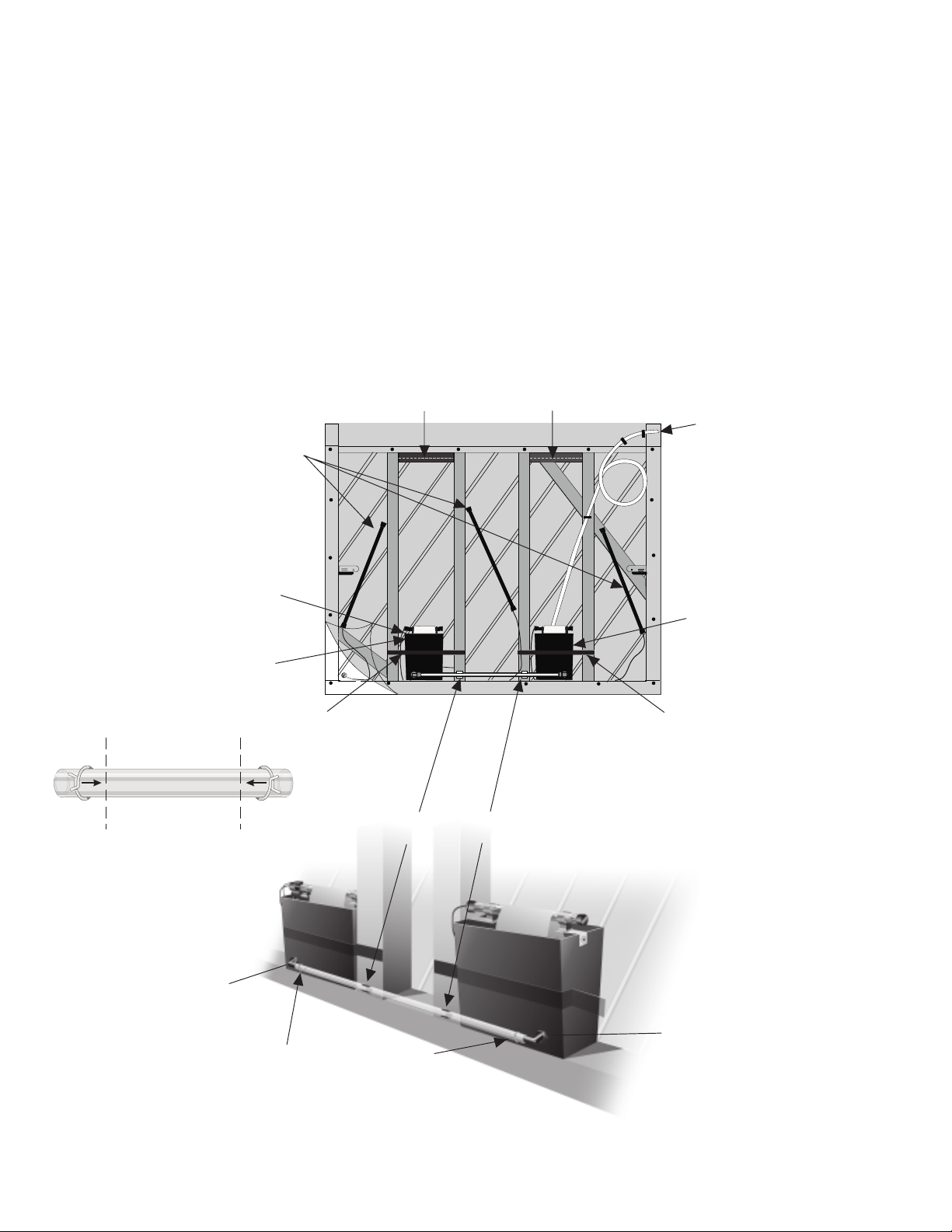
STEP 8. WATERING TUBE INSTALLATION
Run the Watering Tube to the top of the piano as shown in
Figure 8, page 5. It’s important to curve the tube so it can be
pulled out freely for watering. Figure 19 shows the two types
of watering tube clamps included with the System, the 1/2-inch
clamp and the half-clamp. At the top of the piano, mount half-
clamps to hold the end of the tube so it can be removed easily.
Use 1/2-inch screws with serrated washers to anchor the half-
clamps and washers (the serrated washers bite into the wood to
stabilize the clamp). Use the 1/2-inch clamps with 1/2-inch
screws to hold the watering tube between the half clamps and
the Humidifier.
MAKE A NEAT INSTALLATION:
Bundle and secure excess cords in the front and back of the
piano by using the remaining clamps mounted with 1/2-inch
screws.
STEP 9. BACKSIDE COVER INSTALLATION
Install the Cover according to the instructions found in the Cover
box.
After the Piano Life Saver System and the Cover are com-
pletely installed, plug the Humidistat into a non-switchable wall
outlet where it cannot be turned off and therefore will be fully
energized at all times.
STEP 10. WATERING THE SYSTEM
The final step is to fill the Humidifier with water. FILL THE
WATERING CAN TO THE RED LINE ON THE LABEL. Instruct
the piano owner to add one can of water each time the yellow
Low Water Light blinks. Also instruct the piano owner to add
one capful of PAD Treatment to each full watering can. PAD
Treatment inhibits mildew in both the watering tube and the
Humidifier and increases the life of Humidifier pads.
Warning: Add only Dampp-Chaser PAD Treatment to the
Humidifier water. Other brands of water treatment may
contain acids which corrode strings and metal parts in the
piano. The use of other water treatment preparations will void
the warranty of the Piano Life Saver System and may void the
warranty of the piano manufacturer.
If tap water comes from a well or is “hard” water, meaning
containing significant minerals, we recommend using distilled
water. If distilled water is used, add PAD Treatment (according
to the label instructions) to ensure there are adequate electro-
lytes in the Humidifier to support operation of the low water
warning light. Without sufficient electrolytes, the light will blink
continuously, even when the Humidifier is full. Do not put salt
in the Humidifier, as it is corrosive.
To fill the Humidifier, simply pull the watering tube out of the half
clamps, connect the spout inside the watering tube, raise the
watering can, and add water. Then, disconnect the watering can
from the tube and push the tube back into the half clamps. The
System is designed so siphoning will not occur.
This completes the installation of the System.
Humidifier Maintenance: To ensure a properly functioning
Humidifier, the pads should be changed at least twice each
year. This applies whether a Smart Bracket is used or not.
Change them during the fall service of the piano and then again
in the spring. Replacement pads can be obtained from Dampp-
Chaser or from any Dampp-Chaser distributor. Clean the
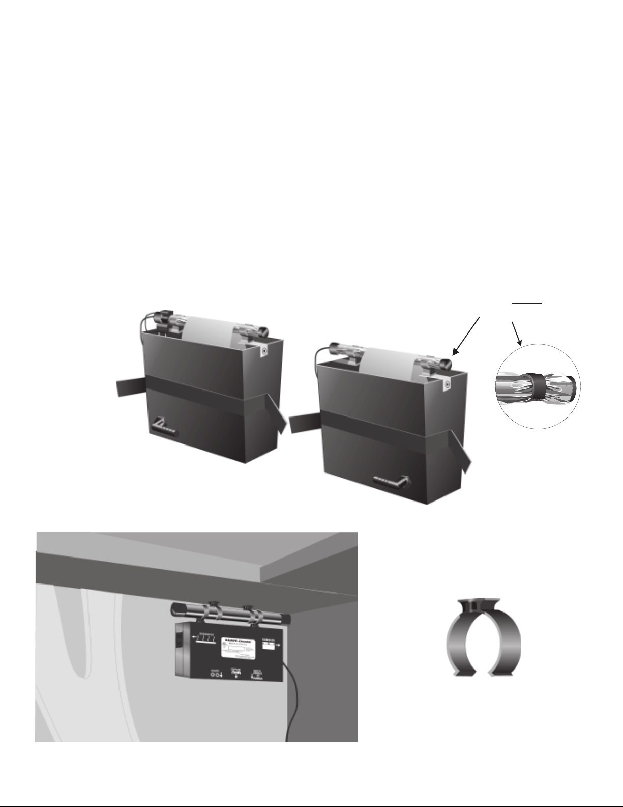
Humidifiers once yearly. When you clean the Humidifiers, also
replace the plastic Clean Sleeves on the Humidifier Heater Bars
to protect the Bars from excessive corrosive minerals in the
water. Cut the sleeves to the correct length.
Smart Bracket Maintenance: The sensor wires of the Smart
Bracket operate more effectively if the wires are kept free from
corrosion and minerals. During pad changing, remove the
Bracket from the Heater Bar. Remove the mineral residue on the
wires by scraping with the dull edge of a knife held perpendicu-
lar to the wire. Alternatively, it may be simpler to bring a new SB
to replace the old one.
You will need to cut the new SB to the correct length with a wire
cutter. Replacement SBs are available from your Dampp-
Chaser distributor.
DAMPP-CHASER’S TECHNICAL SERVICE DEPARTMENT
IS AVAILABLE TO ANSWER ALL INSTALLATION QUESTIONS
AT 800-438-1524.
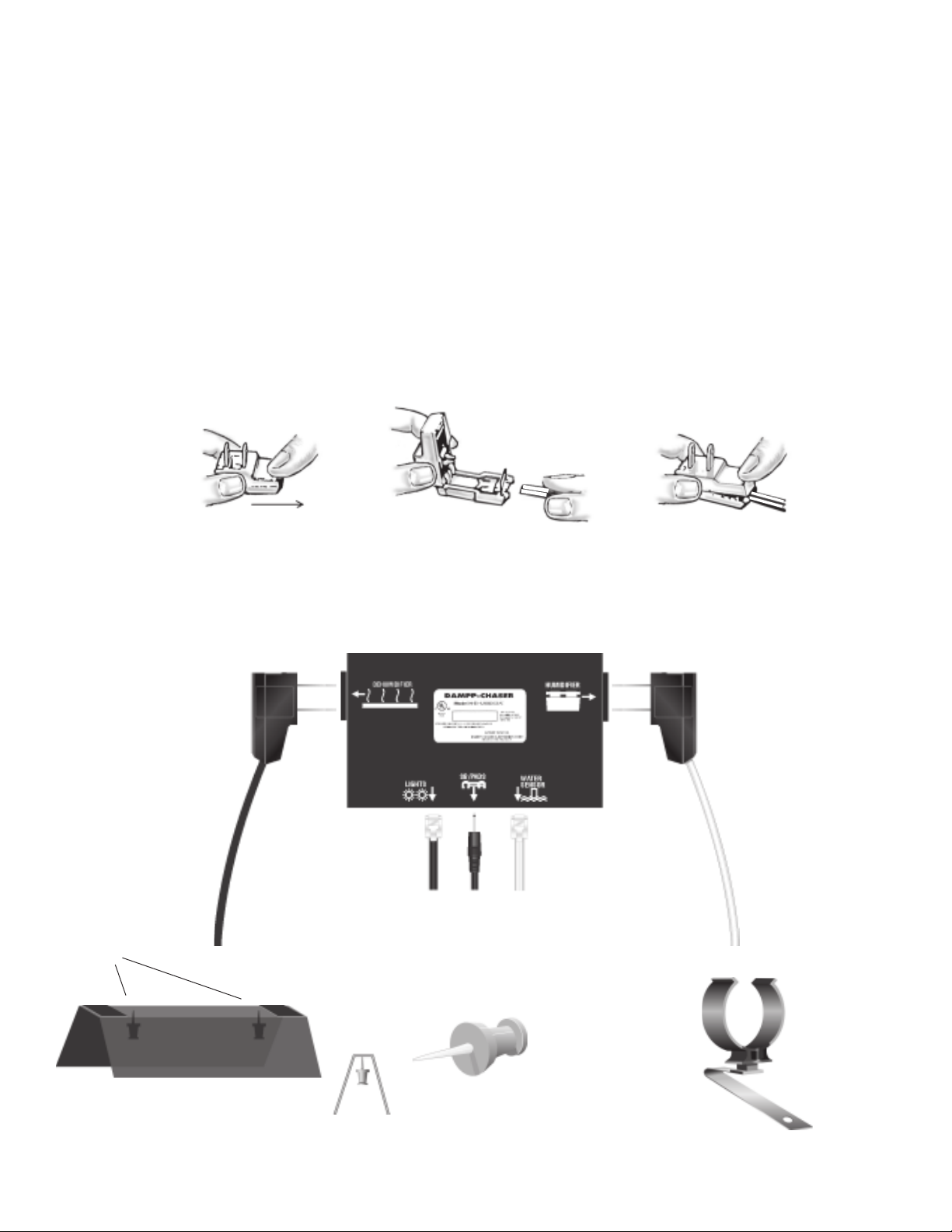
AB
FIGURE 19
Two types of clamps for Watering Tube
(A) 1/2-inch clamp
(B) half clamp