manuals.online logo
Brands
  1. Home
  2. •
  3. Brands
  4. •
  5. EMG
  6. •
  7. Accessories For Musical Instruments
  8. •
  9. EMG TB-HZ Service manual

EMG TB-HZ Service manual

.390
(10)
SOLID
SOLID
(6).235
INSTALLATION INFORMATION
EMG MODELS: TB-HZ PICKUP
Warranty
All EMG Pickups and accessories are warranted for a period of two years. This warranty does not cover failure due to improper installation, abuse or damage. If
upon examination the pickup is determined to be defective, a replacement will be made. Warranty replacement products are covered by this same warranty. This
warranty covers only those pickups and accessories sold by authorized EMG Dealers. This warranty is not transferable.
© 2023 Copyright EMG INC. All Rights Reserved.
PO BOX 4394
SANTA ROSA, CA
95402 USA
P (707) 525-9941
F (707) 575-7046
EMGPICKUPS.COM
0230-0211rF
*Note: Magnet Type: C/S (Ceramic/Steel)
(1) Wired in Series
(2) Loaded with 500K Volume and Tone with a 20’ (6M) Cable
(3) Loaded with 1 MegOhm / 47pf
Installation notes:
The connector system allows an easy method of interchanging pickups. The 5-Wire Cable and wire legend are compatible with all other
EMG-HZ Pickups, so any EMG-HZ Passive Pickup can be installed with any other EMG-HZ Pickup. The 5-Wire cable allows for Series/Parallel
switching (see our solderless Series/Parallel Push Pull Pot) or coil-splitting for certain hardwire setups
See our webiste for more information: emgpickups.com.
SPECIAL NOTE: The Red Wire of the HZ Pickup Cable is NOT for battery power, it is a coil wire.
SPECIFICATIONS: MODEL:
TB-HZ
Logo Color Silver
Magnet Type * C/S
Inductance (Henries) (1) 2.65
DC Resistance (kOhm) 8.0
Resonant Frequency (KHz) (2) 2.85
Resonant Frequency (KHz) (3) 4.90
Impedance at Resonance (kOhm) (2) 47.50
EMG-HZ WIRING
Pin 1 Green (GRN)
Pin 2 White (WHT)
Pin 3 Braid (GND)
Pin 4 Red (RED)
Pin 5 Black (BLK)
BLACK RED
GREEN
WHITE
+_
+_
COIL 2
COIL 1
ADJUSTMENT SCREWS (2)
MONO OUTPUT
JACK
1 VOLUME CONTROL (250K)
BRIDGE GROUND
CONNECTOR
OUTPUT CABLE 6” (15cm)
2 CONNECT CABLES 5.5” (14cm)
BRIDGE GROUND WIRE 6” (15cm)
PICKUP CABLE 15” (30cm)
MAXIMUM RECOMMENDED STRING WIDTH 2.50"
2.900
3.712
1.650
.90
R .375 TYP
3.250
.125”(3.17) DIA. MOUNTING HOLES
(94.28)
(41.91)
(82.55)
(9.52)
(22.85)
(73.65)
12345
Included with THE PICKUP:
1 TONE CONTROL (250K)
Installation Instructions:
EMG Models: TB-HZ
EMG-TB-HZ INSTRUCTIONS Page 2
Common Wiring Diagrams:
Included in this data sheet are the most common wiring diagrams.
The first diagram features wiring for a single pickup, while the
rest are for guitars with 2 Pickups and 2 styles of selection switch.
Diagram #1
Diagram #2
General Notes:
GREEN AND SHIELD
(TO GROUND)
RED
(OUTPUT)
BLACK AND WHITE
Diagram #1 shows the installation of the Pickup Cable.
Be sure to install it with the terminals as shown in the diagram.
Diagram #2 shows the Pickup cable itself. The cable is pre- wired
as shown for “Series” wiring typical of Humbucking Pickups.
If you wish to reverse the phase of the signal refer to Diagram #3.
Send the Red wire to ground with the Shield and use the Green wire
for output. In both cases the Black and White wires are hooked together
and covered with an insulator.
Diagram #3
(Reverse Phase) RED AND SHIELD
(TO GROUND)
GREEN
(OUTPUT)
BLACK AND WHITE
BLACK WIRE INCLUDED
WITH CONNECTOR FOR
BRIDGE GROUND
Diagram #4
One Pickup
One Volume
One Tone
VOLUME250K 500K
B159A
OUTPUT
S
T
250K 500K
B160A
TONE
EMG
MASTER
TONE
OUTPUT CABLE
FROM PICKUP
MASTER
VOLUME
TO STRING GROUND
SEE DIAGRAM #5
Diagram #5
Attaching the bridge ground wire
6) Refer to Diagram #5.
As mentioned on page 1, it is common to “ground” (earth)
the strings on guitars that have passive pickups.
Included with the system is a black wire with a single black
connector attached. Also included is an IDC connector for
connecting the two wires together. Insert the bridge ground wire,
and the connector wire into the IDC connector, crimp the connector
with a pair of pliers until it snaps and this will connect the two wires.
You don’t need to strip the insulation from the wires.
Push the black connector onto terminal 2 (GND) of the volume control
as shown in the diagram. This will ground the strings to the system.
B159A
VOLUME250K
NECK
VOLUME
STRING GROUND WIRE
COMING FROM THE BRIDGE
BLACK WIRE INCLUDED
WITH CONNECTOR
1
2
3
4
5
6
CLOSED
CRIMP
(INSERT WIRES)
245B
EMG
O
NK
BR GND
EMG-TB-HZ INSTRUCTIONS Page 3
****Tips and Tricks****
Start your installation by:
1) Remove the strings
2) Remove any existing Pickups and controls
(remember the order and function of each control)
3) Determine a good spot for the Pickup Buss and make sure the
cable or wires from the selection switch will reach the Pickup Buss,
4) Install the EMG Volume and Tone Controls and tighten them in.
5) Then install the pickups keeping any excess cable under the pickup
rather than in the control cavity.
Diagram #8
FROM
SWITCH
If your instrument has a selection switch:
Shown below is the EMG B245 Pickup Buss which is used for
instruments that have 2 pickups and a 3 position selection switch.
If you have a selection switch and want your installation to
remain solderless, you’ll need a B245 Buss.
Either send an e-mail to: [email protected]
or call: 800 821-1446 to get the buss.
Diagram #8a
Diagram #6
2 Pickups
Volume / Volume/ Tone
B159A
VOLUME250K 500K
250K 500K
B160A
TONE
EMG
MASTER
TONE
OUTPUT CABLE
NECK
VOLUME
BRIDGE
VOLUME
FROM NECK PICKUP
BLACK WIRE
WITH CONNECTOR
TO STRING GROUND
FROM BRIDGE PICKUP
OUTPUT
S
T
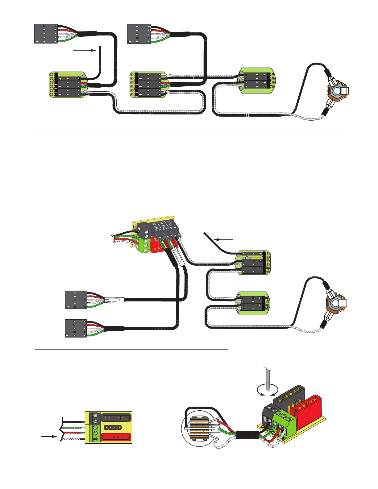
Wiring the Selection Switch
4) Refer to diagrams 8 and 8a, strip the insulation from the switch wires and Insert
them into the GREEN Terminal Block and tighten the screws with a small screwdriver.
The Bridge pickup to the BR Terminal
The Neck pickup to the NK Terminal
The Output of the switch to the OTerminal
If there is a ground wire coming from the switch, insert it into one of the
black (GND) terminals on the terminal block.
1) Install the Pickups and route the Pickup cables to the control cavity.
If the cables are too long, wind up the excess and keep it under the pickup.
2) Mount the Volume and Tone controls into the body.
Plug both Pickup cables into the Pickup Buss (BLACK Shroud) as shown,
Refer to Diagram #7
Bridge Pickup to BR IN
Neck Pickup to NK IN
Diagram #7
2 Pickups
Toggle Style Select Switch
Master Volume / Master Tone
OUTPUT
S
T
MASTER
TONE
FROM NECK PICKUP
FROM BRIDGE PICKUP
MASTER
VOLUME
OUTPUT CABLE
250K 500K
B160A
TONE
EMG
6
5
4
3
2
1
TO STRING GROUND
SEE DIAGRAM #5
TIP
SLEEVE
FROM TONE
OR VOLUME
EMG-TB-HZ INSTRUCTIONS Page 4
Diagram #11
Soldering to the 151 Panel Jack:
If your instrument has a long Panel Jack like the one below
you will have to solder the output cable as shown.
Ground (Black) to the Sleeve
Signal (White) to the Tip
VOLUME250K 500K
B159A
EMG
VOLUME250K
B159A
EMG
OUTPUT
S
T
NK VOLUME
FROM NECK PICKUP
FROM BRIDGE PICKUP
MASTER
TONE
Diagram #9
2 Pickups
Toggle Style Switch
Volume each Pickup
(Volumes are independent)
Master Tone
OUTPUT CABLE
250K 500K
B160A
TONE
EMG
GROUND
BRIDGE P/U
NECK P/U
OUTPUT
BR VOLUME
6
5
4
3
2
1
TO STRING GROUND
SEE DIAGRAM #5
NK VOLUME
OUTPUT
S
T
FROM NECK PICKUP
FROM BRIDGE PICKUP
BR VOLUME
NK TONE
Diagram #10
2 Pickups
2 Volume (either volume will act as a master)
2 Tone
Toggle Style Switch
OUTPUT CABLE
250K 500K
B160A
TONE
EMG
BR TONE
250K 500K
B160A
TONE
TO STRING GROUND
SEE DIAGRAM #5
GROUND
BRIDGE P/U
NECK P/U
OUTPUT

Other EMG Accessories For Musical Instruments manuals

EMG 57 Service manual

EMG

EMG 57 Service manual

EMG X Series Service manual

EMG

EMG X Series Service manual

EMG EXG Service manual

EMG

EMG EXG Service manual

EMG BQC-HZ SYSTEM Service manual

EMG

EMG BQC-HZ SYSTEM Service manual

EMG Pso VG-20 Series Service manual

EMG

EMG Pso VG-20 Series Service manual

EMG Pi2 User manual

EMG

EMG Pi2 User manual

EMG MMTW Service manual

EMG

EMG MMTW Service manual

EMG P-HZ Service manual

EMG

EMG P-HZ Service manual

EMG X Series Service manual

EMG

EMG X Series Service manual

EMG AB 220 Service manual

EMG

EMG AB 220 Service manual

EMG 60-8X Service manual

EMG

EMG 60-8X Service manual

EMG X Series Service manual

EMG

EMG X Series Service manual

EMG ZW Set Service manual

EMG

EMG ZW Set Service manual

EMG JMASTER Service manual

EMG

EMG JMASTER Service manual

EMG P Service manual

EMG

EMG P Service manual

EMG NECK 89R User manual

EMG

EMG NECK 89R User manual

EMG MMTW Service manual

EMG

EMG MMTW Service manual

EMG 35J User manual

EMG

EMG 35J User manual

EMG 91 Service manual

EMG

EMG 91 Service manual

EMG EMG-HZ Series Service manual

EMG

EMG EMG-HZ Series Service manual

EMG RT RIP TIDE Service manual

EMG

EMG RT RIP TIDE Service manual

EMG EMG-91 ARCHTOP Service manual

EMG

EMG EMG-91 ARCHTOP Service manual

EMG 66-7H PICKUP Service manual

EMG

EMG 66-7H PICKUP Service manual

EMG 45-TW Service manual

EMG

EMG 45-TW Service manual

Popular Accessories For Musical Instruments manuals by other brands

Auralex Acoustics Deep6 Installation & user guide

Auralex Acoustics

Auralex Acoustics Deep6 Installation & user guide

DiMarzio J All-in-One Quick Start Guide

DiMarzio

DiMarzio J All-in-One Quick Start Guide

Fishman FLUENCE CUSTOM MATT HEAFY Series installation guide

Fishman

Fishman FLUENCE CUSTOM MATT HEAFY Series installation guide

K&K Sound VIOLINISSIMO product manual

K&K Sound

K&K Sound VIOLINISSIMO product manual

Konig & Meyer Spider Pro 18876 manual

Konig & Meyer

Konig & Meyer Spider Pro 18876 manual

GuitarPCB FXCT manual

GuitarPCB

GuitarPCB FXCT manual

acus Phantasma user manual

acus

acus Phantasma user manual

Mojotone NC-1 Quick installation

Mojotone

Mojotone NC-1 Quick installation

Kawai F-302 Assembly instructions

Kawai

Kawai F-302 Assembly instructions

Behringer AIRPLAY GUITAR AG10 quick start guide

Behringer

Behringer AIRPLAY GUITAR AG10 quick start guide

Roland FS-1-WL Connection guide

Roland

Roland FS-1-WL Connection guide

Dusty Strings TriStander Direction for Installation and Use

Dusty Strings

Dusty Strings TriStander Direction for Installation and Use

Suzuki MRT- 01 manual

Suzuki

Suzuki MRT- 01 manual

Korg GM-1 owner's manual

Korg

Korg GM-1 owner's manual

Schatten Design RG-03 Neo instructions

Schatten Design

Schatten Design RG-03 Neo instructions

Turnstyle T2 manual

Turnstyle

Turnstyle T2 manual

FuzzDog Vintage POW! manual

FuzzDog

FuzzDog Vintage POW! manual

Fishman PowerTap Infinity installation guide

Fishman

Fishman PowerTap Infinity installation guide

manuals.online logo
manuals.online logoBrands
  • About & Mission
  • Contact us
  • Privacy Policy
  • Terms and Conditions

Copyright 2025 Manuals.Online. All Rights Reserved.