VOLUME CONTROL
Diagram #6
Volume Control
Tone (Passive)
SPC Control
TONE CONTROL
(PASSIVE)
SPC CONTROL
OUTPUT TO JACK
VOLUME CONTROL
Diagram #7
Tone (Passive)
SPC Control
Volume Control
TONE CONTROL
(PASSIVE)
SPC CONTROL
OUTPUT TO JACK
SPC / RPC Page 4
3 Pickup Guitars using a selection switch:
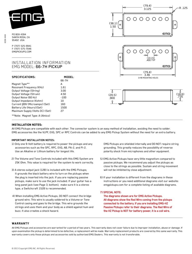
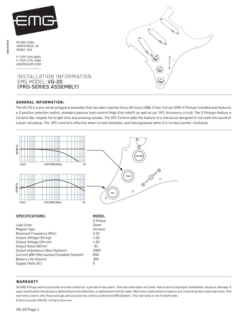
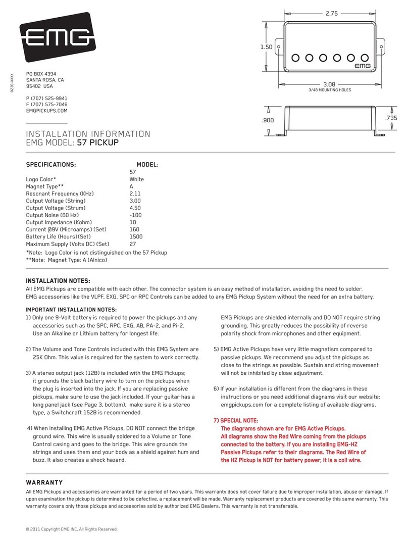
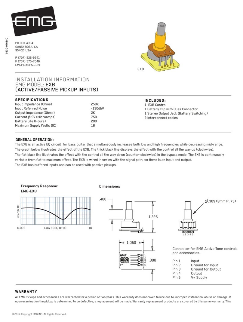
Diagrams #6, #7 show a typical installation with a Volume/Tone/SPC in a
“daisy-chain” series wiring. The only difference between the the diagrams
is the order in which the controls are wired. The diagrams yield the same
results. The diagrams have been edited to show the SPC input, output,
and power (9V+). The pickup inputs, battery, and “ring”contact to the jack
have been omitted for clarity.
All diagrams show the B161 5-Position switch buss. To learn more
about the B161 5-Position switch Buss, go to the EMG Website:
http://www.emgpickups.com.
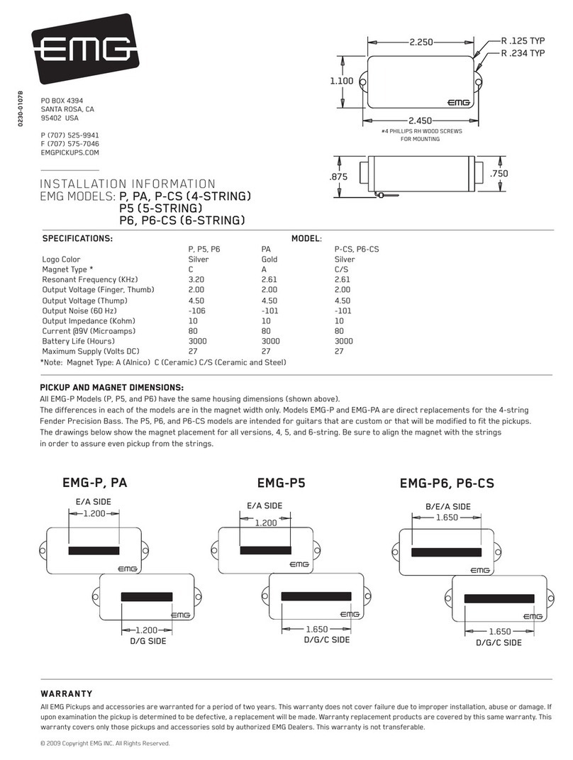
Refer to Diagram #6
Start by installing the SPC or RPC as shown in Diagram #6.
1) Plug a coax cable from the output switch to the Volume control.
2) Plug a coax cable from the Volume control to the Tone control.
3) Plug a coax cable from the Tone control to the input of the SPC.
Be sure to reverse the connector on the input of the SPC as shown.
4) Plug the output cable from the SPC to the output jack.
5) Plug the Red wire from the SPC to one of the supply pins on the
B161 Switch Buss.
Be sure the 3 shunts are installed on the bypass header of the
B161 switch or you won’t get any output from the guitar.
Refer to Diagram #7
Start by installing the SPC or RPC as shown in Diagram #7.
1) Plug a coax cable from the output switch to the Tone control.
2) Plug a coax cable from the Tone control to the input of the SPC.
Be sure to reverse the connector on the input of the SPC as shown.
3) Plug a coax cable from the output of the SPC to the Volume control.
4) Plug the output cable from the Volume control to the output jack.
5) Plug the Red wire from the SPC to one of the supply pins on the
B161 Switch Buss.
Be sure the 3 shunts are installed on the bypass header of the
B161 switch or you won’t get any output from the guitar.
Refer to Diagram #8
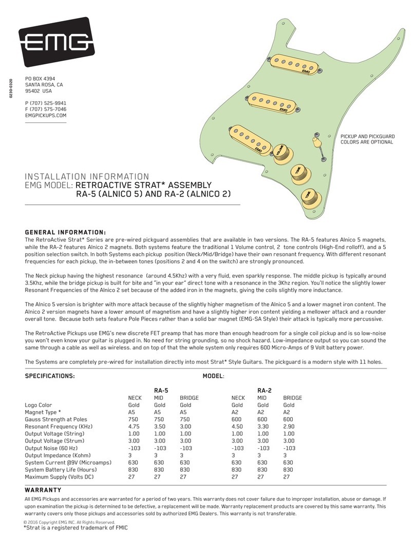
Diagram #8 shows 2 active controls installed: SPC and VLPF. This is
the same as the X Series Pickups that use an active tone (VLPF)
and adding the SPC Control.
Start by installing the SPC or RPC as shown in Diagram #8.
1) Plug a coax cable from the output switch to the Volume control.
2) Plug a coax cable from the Volume control to the input of the VLPF.
Be sure to reverse the connector on the input of the VLPF as shown.
3) Plug a coax cable from the output of the VLPF to the input of the SPC.
Be sure to reverse the connector on the input of the SPC as shown.
4) Plug the output cable from the SPC to the output jack.
5) Plug the Red wires from both the VLPF and SPC to the extra 9V+
supply pins on the B161 Switch Buss.
Be sure the 3 shunts are installed on the bypass header of the
B161 switch or you won’t get any output from the guitar.
VOLUME CONTROL
Diagram #8
Volume Control
Tone (Active VLPF)
SPC Control
TONE CONTROL
(ACTIVE VLPF)
SPC CONTROL
OUTPUT TO JACK
NOTE:
REVERSED CONNECTOR
NOTE:
REVERSED CONNECTOR
NOTE:
REVERSED CONNECTORS
