DANCAR ELFOOT User manual

Copyright: www.dancar.dk
Produktion and distribution: Dancar Autosikring ApS Smedevænget 20 DK 2640 Hedehusene www.dancar.dk tlf: 46591228
Fitting instruction
User manual
remote the steady leg of your Caravan
JKH8007GB/ 01.12.2017

With this kit you will transform the traditional stabilising legs of your caravan into a electrically remote operation. The actuator turn the
existing spindle with enough power for lowering and lifting the legs. The system are not intented to lift or adjust leveling the caranvan.
This must be performed prior lowering the stabiliser legs.
Maintenance
The system do not require any maintenance but the function depends of perfect conditions of your stabiliser legs. Turning the spindle
must be easy able to run freely, and light. Rust, dirt, non greased spindels, screwed or deformed spindels will cause an unintended
functionallity. At least ones a year inspect and maintain all moving parts of the original stabiliser legs. Use only light running PTFE oil.
The battery inside the remote must be removed if system is not in use for a longer periode.
The battery have a life time of about 2 years.
Turning on the remote please press and hold the button «ON» more than 3 sec. Successfully turning ON the remote is indicated
by flashing green, all 4 LED´s. System is now in «automatic» mode. (default).
Note:
If the remote are unable to see the receiver in the caravan, it will warn with red flash on LED «A» in 10 sec. Check caravan power!
With remote in Automatic mode
Shortly activating the button «down», the legs starts to lower one by one. The sequence starts with R rear, Left rear, R front and
finally L front. Every leg stops automatically when touch down force is reached. After all legs are down, the system perform a extra turn
on each legs to ensure full contact to the surface.
When activating shortly the button «UP», the legs starts one by one to lift. After legs are in top possition, they perform a
loosen-operation by turning half turn down. This ensure the leggs not to block, if not used for a longer periode.
Manual operation of legs individually
You are able to provide extra power to each of the individually leg. When remote is in «automatic» mode, you can press shortly
the «ON» button to chose a leg individually. Each pres on the «ON» button will change to anoter leg. The chosen leg are flashing
green, and you can operate by UP or DOWN bottons as you like.
Normally it is not recommanded to provide this extra power. To much load can damage the caravan construction.
Interruption of automatic function will always be possible by simply pressing one of the buttons of the remote shortly. Turn off the main
power (caravan main power switch) will also to stop the function.
Turning off the remote
The remote turn off automatically after 5 minutes if it is not used. (sleep function)
Site 2/8 Copyright: www.dancar.dk
How to use
Warning
Activating the system must be done with greatest attention and it must be ensured that no objects, body parts or animals are nearby the
the satbiliser legs when in motion.
Do not touch the stabiliser legs itself, or nearby when system in powered. Do always turn of the power to the system when not in use.
Important
The system power must always be turned off when towing the caravan. Always check by visual control that the satbiliser legs are in
desired position prior towing the caravan.
!
ON button
DOWN button
UP button
Led «A»

Site 3/8 Copyright: www.dancar.dk
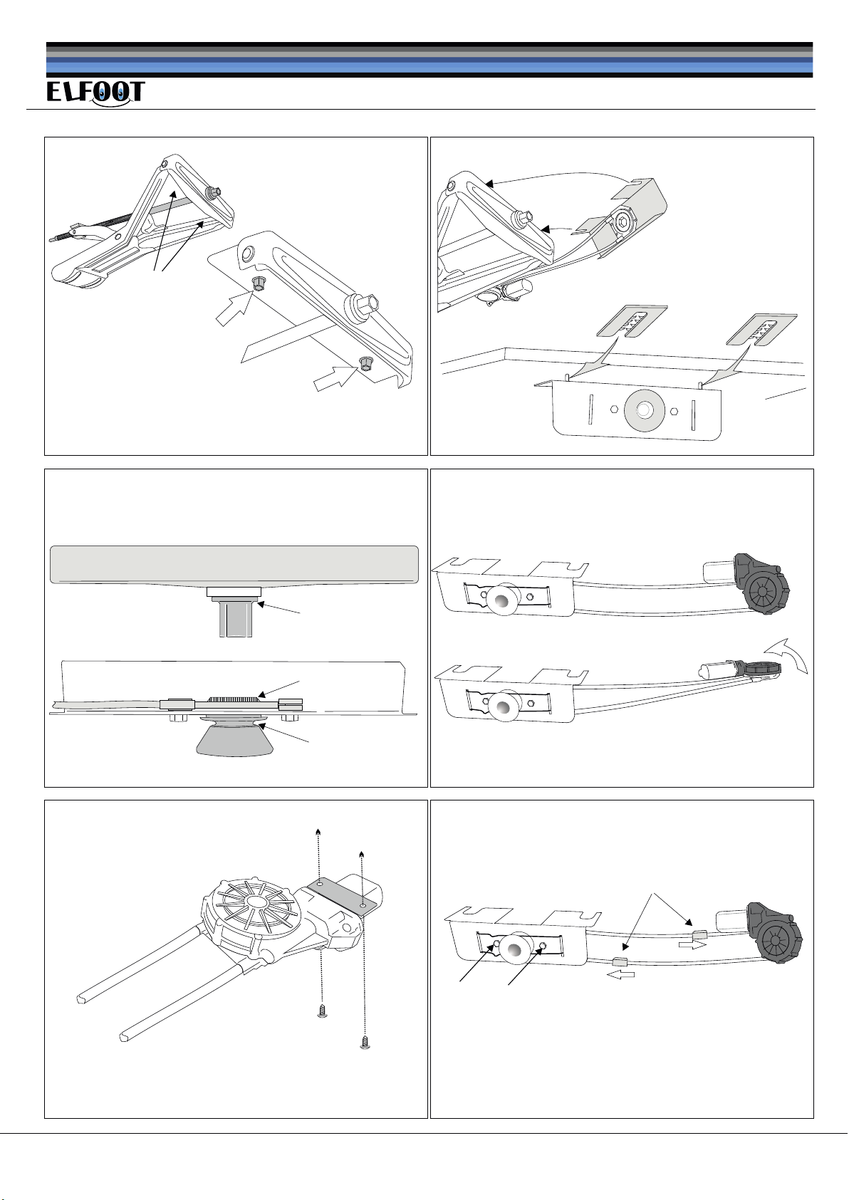
Loosen the stabiliser leg and insertion of the bracket
The bolts holding the stabiliser leg must be loosened (M1). Push in carefully the bracket with the blue adaptor in the gab as indicated
in fig. (M2).
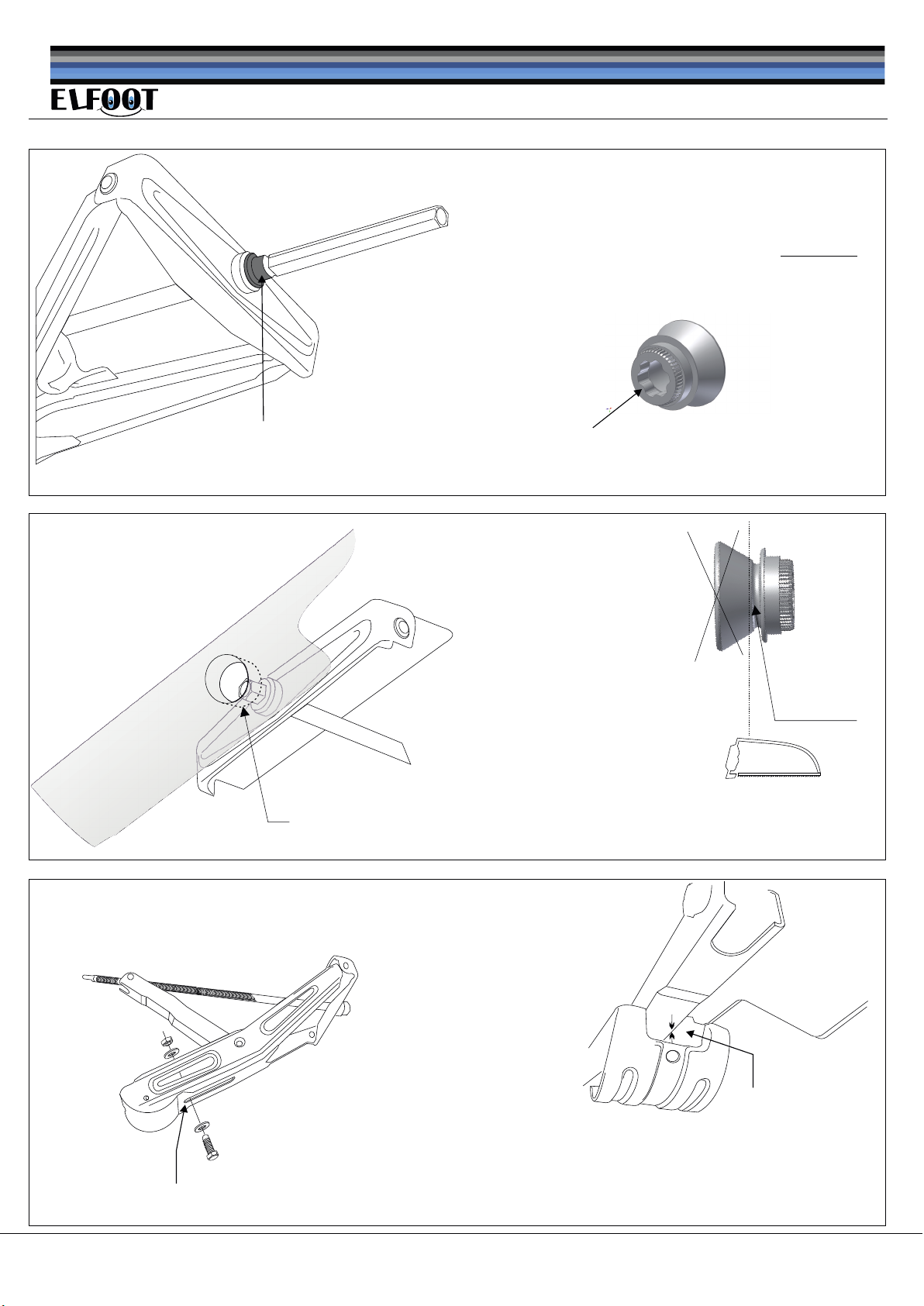
At the same time, if necessary, turn the spindle bolt by hand to make possible insertion of the blue adaptor over the spindle hex bolt.
Push gently the bracket until the adaptor touch the edge of the spindle bolt fig. (M3). Draw 5 mm. backwords to provide space for
movement of the spindle bolt (back and forward).
Re-tighten the bolts fig. (M1)
Fasten the motor
Please turn the motor half way fig. (M4). Possition the motor so the black housing is facing to the bottom plate of the caravan. Turn the
motor in its flexible cables until desired possition. Make sure the cables are bend in a smooth curve as shown in fig. (J). Do never bend
more than 45 degree. Fasten the motor using the two screw provided fig. (M5). Note: The two bolts (A) fig. (M6) must not be tighten
since the gear must be able to follow the up-down movements of the spindle when turning.
Fasten the wires
Please fasten the control unit inside the caravan. Close attachment to the caravan battry is recommended. The red 2" power wire
must be connected via 30 amp. fuse to positive+ battery. Connect the black 2" wire to negative´- battery. Ensure good connections!
Fasten the motor wires in a safe and suitable way and route the ends through whole in cavaran bottom plate. Be carefull when drilling.
Some caravans have floor heating installation! Ensure that the 2 pole connesctors are firmly clicked together with motor part. All
wires have identification each ends. When attachment are finish and wires are inside the caravan, please strip 5 mm. of the ends
and tighten the wires in the screw terminals. Follow the diagram fig. (J)
Finish
Before installation
In order to guarantee a faultless operation and thus exclude the danger to people and objects, this product must be mounted in
accordance with professionals who possess the necessary tecnical knowledge and the necessary tools. The mounting guide must be
read thoroughly. Before starting the mounting you must make sure the mounting kit is complete.
Do alway start the installation with manual check and functionallity of each stabiliser leg. Rotation of the spindle must run freely, and
light. Rust, dirt, non greased spindels, screwed or deformed spindle will cause an unintended functionallity.
The kit contain 4 actuators. Two with black flex and two with gray flex. A pair of these to be mounted each end of the caravan. Fig. (J).
Choose position of the actuator who gives a smooth and easy route of the flexible cables. This will ensure long lasting of the mecanical
cabels.
Please check prior installation that enough space in front of the stabiliser legs are present. In some case it is necessary to create space
by removing plastic part or bending edge of drip-edges. To give better access to the brackets during insertion, the blue adaptor can be
removed temporarily.
Lowering the stabiliser legs
It is helpfull to lower the stabiliser legs a little. This makes it possible to turn, by hand, the spindel a little to match shape of spindle hex
bolt together the inside hex shape of the blue adaptor.
It is essential that gear are able to follow the movements of the spindle (up-down) when turning (bearing clearance). Normally there are
space enough but in some cases it is necessary to provide extra space. In this case insert the shims as shown in fig. (M2)
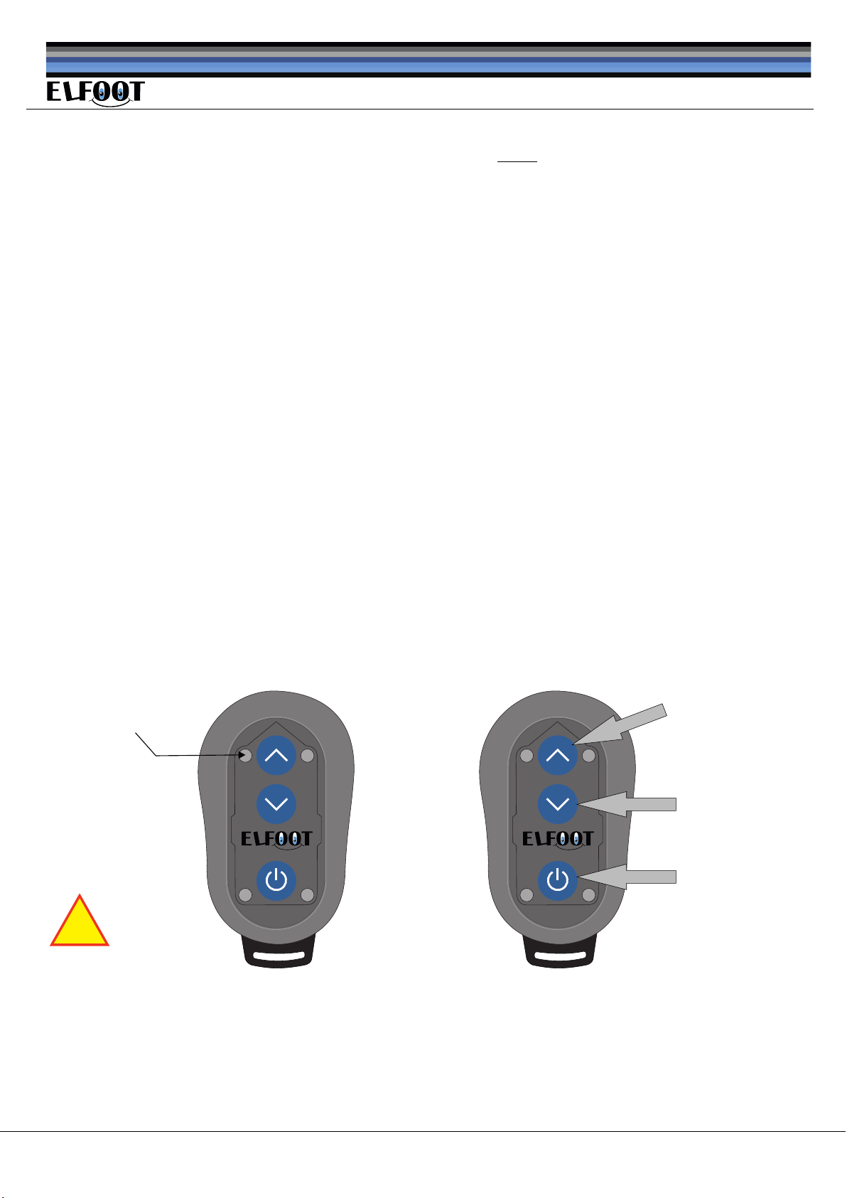
The system have 3 level of settings. The difference is only how much torque the software allow the stabiliser legs to reach before
it stop the motor action. The factory setting is program no. A. Change of program see: settings. Please test all functions after
end of installation.
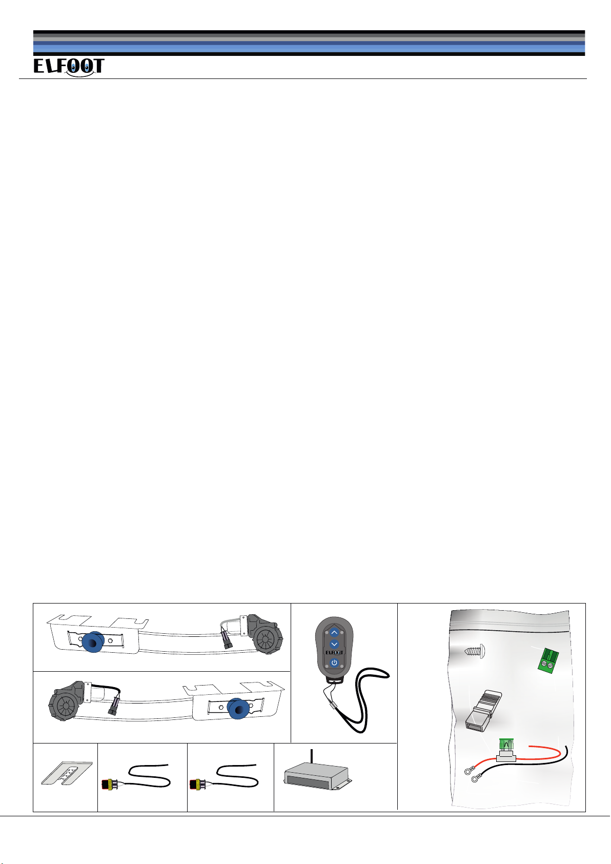
Contents
Installation
2 pcs. Motor with GRAY flex on the wires.
2 pcs. Motor wire 5 m.
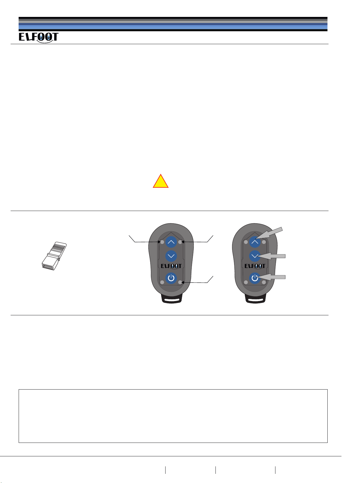
1 pcs. Remote
1 pcs. Control unit
V 4.0
DC0098
DC0088
DC0060
30 amp
8 pcs. Screw
1 pcs. DC0002
power cable
DC0074
DC0050
8 pcs. 4 mm
shims
DC0040 DC0003-5
2 pcs. Motor wire 8 m.
DC0003-8
5 pcs.
2 pole terminal
2 pcs. Motor with BLACK flex on the wires.
Code Jumper

Legs of the
caravan
Fig. M1 Fig. M2
Edge of the
spindelbolt
Adaptor
Fig. M3 Fig. M4
Fig. M5 Fig. M6
A
The two drip-stop must be
pushed to end of the cables
in oppersite direction as show.
Site 4/8 Copyright: www.dancar.dk
A
Do not tighten
Notice: The illustration show a standard leg. In market there might
be types not suitable for the Elfoot adaptor. The standard adaptor
can be modified as shown on page no. 6
shims
Important:
Installation
Spring slot

Site 5/8 Copyright: www.dancar.dk
L.F R.F
seen from top
L.R R.R
Gray
Gray Black
Black
not included
Connections
Fig. J
Main switch
of the caravan
blå
hvid
Control box to be mountet inside the caravan
Please note the possition of
the black and gray wires in the
terminals.
Code Jumper
Rear-L Rear-R Front-L Front-R
ACTUATORS POWERCODE
GND
B+
Standby: current 10 mAh
Current: «Aut» running max. 20 amp
Power supply: 12 V DC.
Fuse: 30 AmP
Patent: PA 2014 00444
Control unit Electrical stabilizer legs
Made by: DANCAR.DK
HW Version: 4.0 SW Version: 4.01
30.11.2017 Test
Blue LED

Site 6/8 Copyright: www.dancar.dk
Note
If the inner section of spindel
is round, adaptor must be
modified.
Please modify the adaptor by removing the first 30 mm.
of the hex-curves. (use cutter drill)
This makes it possible for the adaptor to fully insertion.
6 pcs. hex-curves to be removed
Type of spindle with round attachment
Type of caravan with
skirts (Kabe)
Note:
Not all type of caravans with
skirts are suitable for Elfoot
installation.
In case of emergency operation of the stabiliser
leg, it is essential to have enough space to
be able to remove the adaptor.
Please cut away the innnersection of the
plastic guide tube.
With a mini saw, please
remove the funnel part
of the adaptor. Please save
the spring groove.
Spring groove
Saw
After modification, please check
final distance with fully closed
steady leg.
1 pcs. Bolt 10x45 mm
2 pcs. Washer 2x30 mm
1 pcs. Nut (locking)
Nb. These part are not included
Place bolt on this
location.
This modification make the stady leg stop 35 mm prior fully closed.
This prevent the stady leg to stuck against chassisplate. Adria among others!
Modification to prevent stucking
min. 35 mm distance
Chassis plate

Emergency situation
If the system for some reason, is not possible to operate by the remote, you can always use your handle for manual operation by
following this procerure:
The spring holding the adaptor must be removed as shown in fig. (N1). Take away the adaptor from the toothed wheel fig. (N2). This
makes it possible to use your handle. Observe: The adaptor can be a little tight to remove if legs are loaded (legs are down).
Manual operation must NEVER be performed when adaptor is insertet. Using handle or other tool when adaptor is inserted will damage
the gear of the motor. Waranty void.
Re-insert the adaptor
Please press carefully the adaptor into the tooth wheel fig (N2). Supporting the bracket by holding with fingers fig. (N4). To let the
adaptor pass freely over the spindle hex-bolt, turning the spindle a little is sometimes necessary. Fasten the spring as shown i fig. (N3)
ensuring the spring are firmly in the spring groove. Wrong insertion of the adaptor or spring can cause permanent damage of the
gear. Warant void.
Possible reasons of unintented function (stop working)
The system measure the load when the spindles are turning. If the load are too high, even before the legs touch the ground, it is most
likely that the spindles are in poor conditions. Remove the adaptors, check by manual turning and make necessary service to the legs.
Cleaning away carefully the old grease and use thin PTFE oil for long and smooth operation.
Check the battery and fuse condition.
If one or more steady legs are not moving down as intented, please see page 6. «stucked stady leg»
Emergency
Fig. N1 Fig. N2
Fig. N3 Fig. N4
Site 7/8 Copyright: www.dancar.dk
toothed wheel
Distance between
bracket and
adaptor edge.
Spring groove
Spring
Adaptor

Site 8/8 Copyright: www.dancar.dk
Settings
Learning new transmitter
Turn on the new transmitter by holding down the «ON» for more than 3 sec. Once the LED «A» lights up, release the «ON» botton,
The LED lights RED the next 30 sec. Within this time you must insert the code jumper in the receiver «code bridge» pins. Doing this will
automatic pair the units, confirmed by all led´s are flashing GREEN. Remove the code jumper. Remote are ready to use!
Only the new coded remote can operate the system.
Note:
A remote who already has been paired must be cleared in key-memory before attempting the «Learning new transmitter»
procedure . To clear key-memory please make following rutine:
Press the «UP» botton and hold it down. Now, press also the «ON» botton and hold it down. Holding these two bottons down at same
time in more than 3 sec. will clear the key-memory. The transmitter is ready for « Learning new transmitter»
Change setting for the load to surface
Please turn ON the transmitter. Insert the Code Jumper in the controlbox. Blue LED in box is lightning as long as Jumper is inserted.
With the remote please select the desired program you wish, by short press of the «ON» botton. When desired program LED
lights up, please press the «UP» botton to set/save.
Remove the Code Jumper. System is ready to use.
Program. A small caravan (default setting)
Program. B medium caravan
Program. C large caravan
This setting will change only the load provided to the ground when using the «automatic down» function. This is normally not to be
changed since it is made during the installation. Remember: too high load can damage the construstion of the caravan.
Warrenty
Factory warrenty is 2 years from the day of sale. Warrenty covers all parts except the remote battery. Warrenty is granted under
condition of normal usage. The product is only intented to be used for private purpose, not commersial use.
Any claim is rejected if parts or product are used unintented or having physical damage of any kind. Warrenty do not cover any 3. party
claims nor any compesation of disadvantage or cost related to missing or not working product. Any claim must be followed by decribtion
and reason. Further the original invoice must be enclosed.
Tecnical data
Produktion and distribution: Dancar Autosikring ApS Smedevaenget 20 DK 2640 Hedehusene www.dancar.dk
Power: 12 to 14 volt DC
Max load motor: 16 amp.
Fuse: 30 amp ATO fuse
Stand by consumption: 13 mA
Transm. freq.:
Weight: 5.6 kg.
Elfoot is a international trademark
Battery transm. Coin type 2450
2.4 Gh
Patent: PA 2014 00444
Working temperature: -10 til 50 celcius.
Production country EU: denmark
Warrenty: 2 year mecanical parts
Warranty: 5 year controlbox and transmitter.
Production inv.: RoHS og EMC direktiv.
!
Contents and informations in this document can be changed without any pre-warning. Updated instruction see: dancar.dk
All material are copyright to Dancar and must not be copy, used in full or part without written permission from Dancar.dk
Code Jumper ON button
DOWN button
UP button
Led «A» Led «B»
Led «C»
JKH8007GB/ 01.12.2017
Table of contents