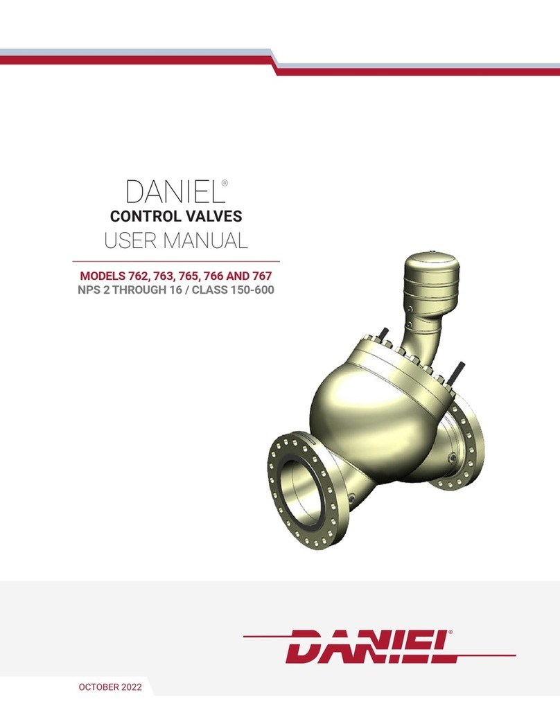
DANIEL 700 User manual

NOVEMBER 2020
DANIEL
®
CONTROL VALVES
USER MANUAL
MODEL 700
NPS 2 THROUGH 16 / CLASS 150-600
Decades Proven. Field Chosen.
™

2 www.Daniel.com
MODEL 700 CONTROL VALVE
Contents
Part I Plan
Chapter 1 Introduction.............................................................................................................. 7
1.1 Purpose of this manual................................................................................................................ 7
1.2 Hazard messages.........................................................................................................................7
1.3 Personnel qualifications...............................................................................................................7
1.4 Warranty restrictions................................................................................................................... 9
1.5 Assistance....................................................................................................................................9
1.6 Description of the Model 700 Control Valves............................................................................... 9
1.7 Agency certifications for control valves Model 700.................................................................... 18
Chapter 2 Operating conditions and specifications...................................................................19
2.1 Operating conditions for the control valve.................................................................................19
2.2 Specifications for the control valve............................................................................................ 23
Chapter 3 Control valve handling............................................................................................. 27
3.1 Receive the control valve........................................................................................................... 27
3.2 Store the control valve...............................................................................................................27
Chapter 4 Prepare the control valve for use.............................................................................. 29
4.1 Lifting conditions.......................................................................................................................29
4.2 Lifting requirements for personnel.............................................................................................30
4.3 Configure the control valve........................................................................................................32
Part II Install
Chapter 5 Installation prerequisites......................................................................................... 37
5.1 Pre-start checks......................................................................................................................... 37
Chapter 6 Installation procedure..............................................................................................39
6.1 External components assembly................................................................................................. 39
Chapter 7 Testing the product..................................................................................................41
7.1 Commission the control valve....................................................................................................41
Part III Operate
Chapter 8 Operation parameters..............................................................................................45
8.1 Control valve normal operation................................................................................................. 45
8.2 Operation accessories................................................................................................................45
8.3 Operation overview................................................................................................................... 45
User manual Contents
P/N 3-9008-553 November 2020
User manual 3

3
www.Daniel.com
USER MANUAL
Part IV Maintain
Chapter 9 Planned maintenance...............................................................................................49
9.1 Maintenance considerations......................................................................................................49
9.2 Tools required for mechanical components............................................................................... 49
9.3 Disassemble/Assemble the control valve................................................................................... 49
9.4 Mechanical assembly................................................................................................................. 53
9.5 Planned maintenance tasks....................................................................................................... 62
Chapter 10 Corrective maintenance........................................................................................... 63
10.1 Control valve troubleshooting................................................................................................. 63
10.2 Verify the return to operational condition................................................................................64
Chapter 11 Spare parts...............................................................................................................65
11.1 Order spare parts.....................................................................................................................65
Chapter 12 Decommission......................................................................................................... 67
12.1 Shut down the control valve.................................................................................................... 67
12.2 Shipment of the control valve.................................................................................................. 67
Contents User manual
November 2020 P/N 3-9008-553
4 Daniel Series 700 Control Valve

4 www.Daniel.com
MODEL 700 CONTROL VALVE
Part I
Plan
User manual Plan
P/N 3-9008-553 November 2020
User manual 5

5
www.Daniel.com
USER MANUAL
1 Introduction
1.1 Purpose of this manual
This manual provides guidance to owners and personnel in the installation, operation and
maintenance of the DanielTM Model 700 Control Valve manual, 3-9008-553. It is imperative
that product owners and operation personnel read and follow the information contained
in this manual to ensure that the control valve is installed correctly and is operating
according to the design certifications and safety considerations.
1.2 Hazard messages
This document uses the following criteria for hazard messages based on ANSI standards
Z535.6-2011 (R2017).
DANGER
Serious injury or death will occur if a hazardous situation is not avoided.
WARNING
Serious injury or death could occur if a hazardous situation is not avoided.
CAUTION
Minor or moderate injury will or could occur if a hazardous situation is not avoided.
NOTICE
Data loss, property damage, hardware damage, or software damage can occur if a
situation is not avoided. There is no credible risk of physical injury.
Physical access
NOTICE
Unauthorized personnel can potentially cause significant damage and/or misconfiguration
of end users' equipment. Protect against all intentional or unintentional unauthorized use.
Physical security is an important part of any security program and fundamental to
protecting your system. Restrict physical access to protect users' assets. This is true for all
systems used within the facility.
1.3 Personnel qualifications
Read and follow all instructions, dangers, warnings, and cautions to avoid personal injury
or property damage during system operation. Daniel is not responsible for damage or
injury resulting from unsafe use of products, lack of maintenance, incorrect installation of
equipment or system operation. If in doubt about any applications and safety precautions
described in this document, contact Daniel.
User manual Introduction
P/N 3-9008-553 November 2020
User manual 7

6 www.Daniel.com
MODEL 700 CONTROL VALVE
Inform and train all personnel in the proper installation, operation, and maintenance of
this product. To ensure safe and proper performance, only informed and trained personnel
should install, operate, repair and maintain this product. For further questions about
training requirements, contact your local Daniel representative.
Operations risk assessment must be used and followed in conjunction with this document
when performing all online retrieval operations.
Ensure that all end user and installation specific safety requirements are read, understood
and adhered to.
Ensure that any operator that is conducting work on the equipment, is following end user
guidelines on the use of protective equipment including, but not limited to:
•Safety helmet or hard hat
•Steel-toed shoes
•Safety glasses
•Working gloves (suitable for mechanical operations)
•Chemical resistant latex gloves or the equivalent
•Long-sleeved, fire-retardant shirt and fire-retardant trousers or full-length fire
retardant coveralls
Additional PPE may be required depending on facility requirements and MSDS
requirements, if applicable. Failure to comply may result in personnel injury.
WARNING
RISK TO PERSONNEL AND EQUIPMENT
Failure to follow the installation, operation or maintenance instructions for a Daniel
product could lead to serious injury or death from explosion or exposure to dangerous
substances. To reduce the risk:
•Comply with all information on the product, in this manual, and in any local and
national codes that apply to this product.
•Do not allow untrained personnel to work with this product.
•Use Daniel parts and work procedures specified in this manual.
NOTICE
Observe all precautionary signs posted on the equipment to avoid serious injury.
WARNING
RISK TO PERSONNEL AND EQUIPMENT
Operation of this product on pressurized lines may potentially imply operational risk for
personnel and equipment from the potential escape of hot gas or liquid, which could
result in serious injury.
Observe all precautionary signs on the equipment.
Introduction User manual
November 2020 P/N 3-9008-553
8 Daniel Series 700 Control Valve

7
www.Daniel.com
USER MANUAL
WARNING
RISK TO PERSONNEL AND EQUIPMENT
The operation of the Daniel product involves heavy equipment handling. Observe the
following guidelines to avoid potentially serious injury:
•Be aware of your limitations and ask for assistance if needed.
•Do not attempt to lift weight beyond your capacity.
•Lift with your legs, not your back.
Note
Mechanical lifting tools may also be used in some locations to reduce risk.
NOTICE
Attending the training course for this product is not considered sufficient for operating the
tool on pressurized lines. Daniel requires a two-man crew with formal training.
Additionally, at least one of the operators must have a record of extensive field experience
and be certified for this work.
1.4
1.5
1.6
1.6.1
Daniel assumes no responsibility for incidents, or consequences of incidents, occurring as
a result of the use of this product by others than Daniel or its designated personnel, and
have no liability whatsoever for any such work.
Consult Daniel for more details on both training and certification.
Warranty restrictions
Visually inspect all components for shipping damage. If shipping damage is found, notify
the carrier at once. Shipping damage is not covered by the warranty. The carrier is
responsible for all repair and replacement costs resulting from shipment damage.
Assistance
The Daniel Global Service Center is organized through a network of service centers
worldwide, and supports all service requirements or technical queries. For the Product
Support Help Desk, go to: http://www.Daniel.com or contact your nearest Daniel service
provider.
Description of the Model 700 Control Valves
General features of the control valve
The Daniel™Model 700 Control Valve operates on a balanced piston principle, spring
biased (loaded) to the closed position.
The valve can be configured as a check valve to prevent reverse flow. It is possible, in some
applications, to reverse flow through the pilot control loop, but this can be eliminated by
installing a check valve in the X-port.
User manual Introduction
P/N 3-9008-553 November 2020
User manual 9

8 www.Daniel.com
MODEL 700 CONTROL VALVE
The Daniel Model 700 Control Valves have the following characteristics:
•Modular construction: All internal parts including seat ring can be removed with the
cylinder assembly without disturbing line connections.
•No diaphragms or stuffing boxes
•45° body design assures high capacity
•Positive shut-off
•Uniform speed-of-response
•Linear control
•O-ring plus metal-to-metal seat
•Pilots and other optional accessories enable the valve to perform a variety of control
functions such as back pressure control, regulating rate-of-flow, pressure relief, surge
control, etc.
1.6.2 Control valve applications
This is the starting point for unlimited control applications. The basic valve needs to
incorporate a pilot control loop, which is mandatory for it to function, see Daniel Liquid
Control Valves Technical Guide (P/N DAN-LIQ-TG-44) for specific applications.
1.6.3 Operation overview of the control valve
The basic valve operates on a balanced piston principle, spring biased (loaded). Refer to
Figure 1-1. The term balanced piston means that the exposed area on the spring side (P3)
of the piston and the bottom side (P1) are equal in area. The spring is the differential force
that closes the piston when (P1) and (P3) pressures are equal.
To open the valve, the pressure against the bottom of the piston (P1) must exceed the
pressure on the spring side of the piston (P3) plus spring force.
Closed position
Figure 1-1 illustrates the closed valve. Y-port (P3) to Z-port (P2) is closed. X-port (P1) and
Y-port (P3) pressures are balanced. The differential force created by the main valve spring,
closes the piston and keeps it seated.
Therefore, total pressure equals 40 psi @ (P1) and 45 psi @ (P3) or (P3 minus P1) - 5 psid.
The needle valve/strainer controls the speed of the closure by controlling the flow through
the X-port.
Introduction User manual
November 2020 P/N 3-9008-553
10 Daniel Series 700 Control Valve

9
www.Daniel.com
USER MANUAL
Figure 1-1: Pilot in closed position
A. Needle valve / strainer
B. Manual pilot control
C. Inlet pressure
D. Outlet pressure
Fully open - No control
In Figure 1-2 the valve is fully open. Y-port (P3) is open to Z-port (P2). The pressure on the
bottom of the piston (P1) is greater than the pressure at (P3) plus spring force. The valve
will not open unless the pressure drop across the valve (P1 minus P2) is slightly greater
than the force applied by the main valve spring. In a non-control state, the main valve is
opened in a percentage directly proportional to (P1 minus P2).
User manual Introduction
P/N 3-9008-553 November 2020
User manual 11

10 www.Daniel.com
MODEL 700 CONTROL VALVE
Figure 1-2: Pilot in fully open position
A. Needle valve / strainer
B. Manual pilot control
C. Inlet pressure
D. Outlet pressure
Open controlled position
In Figure 1-3 the valve is partially open. Y-port (P3) is open to Z-port (P2) but is being
restricted by the control pilot. The pilot control is a variable orifice that regulates the
pressure at Y-port (P3) by controlling the flow through Z-port. Increasing or decreasing the
Y-port pressure (P3) causes the piston to change positions.
Introduction User manual
November 2020 P/N 3-9008-553
12 Daniel Series 700 Control Valve

11
www.Daniel.com
USER MANUAL
Figure 1-3: Pilot in partially open position
A. Needle valve / strainer
B. Manual pilot control
C. Inlet pressure
D. Outlet pressure
E. Controlled pressure
User manual Introduction
P/N 3-9008-553 November 2020
User manual 13

12 www.Daniel.com
MODEL 700 CONTROL VALVE
1.6.4 Parts list for the Series 700 Control Valves
Figure 1-4: Part identification for an NPS 2-12 inch Control Valve
NOTICE
Item numbers are not meant to be consecutively numbered.
Table 1-1: Part description for Model 700 Control Valve NPS 2 - 12
Item number Description Quantity
1 Cylinder 1
2 O-ring 1
3 Seat ring 1
4 Piston 1
5 O-ring 1
6 Backup ring 2
7 O-ring 2
8 Retaining ring 1
9 Washer 1
Introduction User manual
November 2020 P/N 3-9008-553
14 Daniel Series 700 Control Valve

13
www.Daniel.com
USER MANUAL
Table 1-1: Part description for Model 700 Control Valve NPS 2 - 12 (continued)
Item number Description Quantity
10 Retaining ring 1
11 Spring 1
12 O-ring 1
13 Cylinder head 1
16 Screw 4
17 Jack-out screws 2
18 Indicator stem visual 1
Indicator stem micro-switch
19 Magnet 2
20 Retaining ring 1
21 Indicator adapter 1
22 Cap plug 1
23 Ring magnet 1
24 Indicator housing 1
25 Indicator top 1
26 Screw 1
27 Bal-seal 2
28 Piston seal retainer 2
29 External retaining ring 2
31 Nuts 8
32 Valve body 1
33 Studs 8
34 Pipe plug 2
38 Cap plug 1
39 O-ring 1
40 Seal retainer 1
41 O-ring 1
42 Backup ring 2
43 Upper bearing 1
44 Indicator guard 1
45 Lock washer 2
46 Screws 2
47 Indicator adapter 1
User manual Introduction
P/N 3-9008-553 November 2020
User manual 15

14 www.Daniel.com
MODEL 700 CONTROL VALVE
Table 1-1: Part description for Model 700 Control Valve NPS 2 - 12 (continued)
Item number Description Quantity
48 Cap plug 1
50 Set Screw 1
A Cylinder assembly class 150 and
300
Cylinder assembly class 600
Introduction User manual
November 2020 P/N 3-9008-553
16 Daniel Series 700 Control Valve

15
www.Daniel.com
USER MANUAL
Figure 1-5: Part identification for an NPS 16 inch Control Valve
Table 1-2: Part description for Model 700 Control Valve NPS 16
Item number Description Quantity
1 Cylinder 1
2 O-ring 1
3 Seat ring 1
4 Piston 1
5 O-ring 1
User manual Introduction
P/N 3-9008-553 November 2020
User manual 17

16 www.Daniel.com
MODEL 700 CONTROL VALVE
Table 1-2: Part description for Model 700 Control Valve NPS 16 (continued)
Item number Description Quantity
6 Backup ring 2
7 O-ring 2
11 Spring 2
12 O-ring 1
13 Cylinder head 1
14 O-ring 8
16 Screw 24
17 Jack-out screws 2
18 Indicator stem micro-switch 1
31 Nuts 8
32 Valve body 1
33 Studs 40
34 Pipe plug 2
38 Cap plug 1
39 O-ring 8
43 Upper bearing 1
44 Indicator guard 1
45 Screw 2
46 Washer 2
47 Indicator adapter 1
55 Indicator Ext. guard 1
56 Screw 4
57 Washer 4
58 Piston plug 1
59 Screw 3
1.7 Agency certifications for control valves Model
700
The following product agency certifications are applicable to the Daniel control valves.
Table 1-3: Agency certifications for control valves
Certification type Description
Pressure equipment PED
Introduction User manual
November 2020 P/N 3-9008-553
18 Daniel Series 700 Control Valve

17
www.Daniel.com
USER MANUAL
2 Operating conditions and
specifications
2.1 Operating conditions for the control valve
Table 2-1: Operating conditions for the control valve
Condition type Description
Fluid phase Liquid
Process temperature -20° F to 150° F (-29° C to 66° C)
Optional process
temperature
-50° F to 400° F (-46° C to 205° C )
Fluid velocity Operational recommended flow velocity up to 30 ft/sec, beyond this
point will result in a high pressure drop and increased wear.
Fluid(s) controlled •Low/Medium viscosity crude oils and condensates
•Refined products and intermediates (ie: gasoline, diesel, kerosene,
light fuel oils, jet fuel, LPG, butanes, naphtha, alkylate, reformate,
straight run gasoline, cat-cracked gasoline)
•Petrochemicals (ie: benzene, toluene, xylenes, cumene, olefins,
pyrolysis gasoline)
•Natural gas liquids
Viscosity limits on valves
and valves with pilots
•Maximum valve viscosity is 8800 Cst
•Maximum viscosity for valves with pilots is 440 Cst due to
response time of high viscosity pilot
Differential pressure The maximum allowable differential pressure across a control valve is
6894 kPa (1,000 psi). Consult factory for location of first shut down
valve.
Atmospheric pressure Absolute
Sizes (NPS) 2, 3, 4, 6, 8,10,12,16
Pressure class (ANSI) 150, 300, 600
Maximum safe working
temperature range
•15° F to 400° F (-26° C to 204° C)
•Using FKM O-rings
•Temperature range is dependent of O-ring Tmin and Tmax
•Max temperature of valves with solenoid pilots is standard -20° F
to 150° F (-29° C to 66° C) (if applicable), Optional 250° F (121° C)
•Consult the factory for other safe working temperatures
User manual Operating conditions and specifications
P/N 3-9008-553 November 2020
User manual 19

18 www.Daniel.com
MODEL 700 CONTROL VALVE
Table 2-1: Operating conditions for the control valve (continued)
Condition type Description
Maximum safe working
pressure
Flange connections/Ratings (DIN) for valve sizes DN50 and DN400:
•DIN PN16 MWP at 120° C: 16 bar
•DIN PN25 MWP at 120° C: 25 bar
•DIN PN40 MWP at 120° C: 40 bar
•DIN PN64 (class 300) MWP at 120° C: 51 bar
•DIN PN64 (class 600) MWP at 120° C: 64 bar
•DIN PN100 MWP at 120° C: 100 bar
Flange connections/Ratings (ANSI) for valve sizes 2-in to 16-in:
•Class 150 MWP at 100° F: 285 psi
•Class 300 MWP at 100° F: 740 psi
•Class 600 MWP at 100° F: 1480 psi
* MWP: Maximum Working Pressure
Materials of construction Main valve body: Steel, ASTM-A352 Gr. LCC
Main valve cylinder:
•NPS 2-4: Stainless steel
•NPS 6 and larger: Nickel coated steel
Main valve piston: Stainless steel (standard)
Seat ring:
•Class 150 and 300:
—NPS 2-6: Stainless steel
—NPS 8-16: Nickel coated steel
•Class 600: Stainless steel
O-Rings:
•Standard: FKM
•Optional: CR, EPR, FKM V1289, NBR, FFKM, FKM GLT
•For other material contact the factory
External hook up:
•Class 150 and 300:
—NPS 2-6: Carbon steel/Stainless steel 10 mm (0.375-in)
—NPS 8-16 Carbon steel/Stainless steel 13 mm (0.5-in)
•Class 600:
—NPS 2-6: Stainless steel 13 mm (0.5-in)
—Can be furnished in metric sizes
Other internal parts: Stainless steel
Operating conditions and specifications User manual
November 2020 P/N 3-9008-553
20 Daniel Series 700 Control Valve

19
www.Daniel.com
USER MANUAL
Table 2-1: Operating conditions for the control valve (continued)
Condition type Description
Valve capacity Cvis a capacity coefficient that defines as the number of US gpm of
water that flows through a valve with a pressure drop of 1 psi across
the valve. Daniel valves have the following Cv:
•NPS 2: 86 gpm
•NPS 3: 186 gpm
•NPS 4: 309 gpm
•NPS 6: 688 gpm
•NPS 8: 1296 gpm
•NPS 10: 2040 gpm
•NPS 12: 2920 gpm
•NPS 16: 5360 gpm
*Cvbased on wide open valve with water temperature at 60° F (16° C)
2.1.1 Design considerations
Some conditions to consider:
•Service operating pressure
•Service testing pressures
•Service process temperature and ambient site temperatures
•Chemical composition and toxicity of fluid in operating conditions
•Traffic, wind and earthquake at loading site
•Adverse force or stress caused by inadequate supports, attachments, piping, etc.
•Corrosion, erosion, fatigue, etc.
•Decomposition of unstable fluids in operating and test conditions
•Possible damage from external fire
•Mass fluid in process and test conditions
WARNING
FUNCTIONAL AND ENVIRONMENTAL HAZARD
Evaluate the functional and environmental conditions prior to installing a control valve.
Install the control valve in a well-designed piping system.
Failure to comply may result in death or serious injury from pipe failure.
User manual Operating conditions and specifications
P/N 3-9008-553 November 2020
User manual 21

20 www.Daniel.com
MODEL 700 CONTROL VALVE
2.1.2 Environmental conditions
WARNING
EQUIPMENT HAZARD
Never use this equipment for any purpose other than its intended use.
Failure to comply may result in death, serious personal injury and/or property damage.
Table 2-2: Environmental conditions
Parameter type Description
Severe service conditions Ensure that piping or other attachments connected to the valve
are not under stress. The design of the control valve has not
been assessed for the effects of wind, earthquake loading and
severe weather conditions.
Additional severe service
conditions
The valves are designed to be used on liquid applications for
crude oil and refined products.
The use of aggressive additives or oxygenates requires the use
of the Aggressive Products (AP) option. The AP option valve
cylinder incorporates cup-seals (PTFE Bal Seals) and an O-ring
made from appropriate materials for severe conditions.
Corrosive service Select the material compatible with the specific processes and
atmospheric environments. Implement a periodic inspection
and maintenance program to ensure that pressure retaining
components are free from corrosion and erosion.
The valve is not designed with corrosion allowance. Inspect the
valve's metal parts periodically for corrosion and erosion, and
inspect the seals and O-rings for wear and chemical
deterioration.
Low and freezing temperatures Low specific gravities or high viscosities reduce the flow range of
the valve. Refer to Operating conditions for the control valve for
more information.
Populated areas For new installations, locate the control valve to an area that has
fewer than 10 buildings intended for human occupancy within
an area that extends 200 meters (220 yards) radially from the
control valve. (Reference: Class 1 Location: U.S. DOT, CFR Title
49: Part 192.5)
Closed, poorly ventilated areas Install the control valve in a well ventilated area, not less than
one meter (approximately three feet) from source of ignition or
source of heat which might damage the unit.
Elevation No limit
Humidity No limit
Proximity to open flame Provide fire prevention measures and equipment per local
regulations.
Proximity to vehicular traffic The design of the control valve has not been assessed for the
effects of traffic.
Operating conditions and specifications User manual
November 2020 P/N 3-9008-553
22 Daniel Series 700 Control Valve
This manual suits for next models
1
Table of contents
Other DANIEL Control Unit manuals
Popular Control Unit manuals by other brands

Campbell
Campbell SDM-AO4A product manual

Danaher Motion
Danaher Motion Amplifier MDM-7 Operator's manual

Quectel
Quectel RM500Q-AE manual

ALCO CONTROLS
ALCO CONTROLS PS1 Series operating instructions

GEM
GEM 643 Series Installation, operating and maintenance instructions

Acromag
Acromag IP502 Series user manual