Dante DN1126 User manual

DN1126
1/3” H.264/MPEG4/MJPEG
550TVL Day/Night IP Cam ra
Installation and Operations Manual
Model Numbers: DN1125A1, DN1125B1
DN1125A4, DN1125B4
Description: H.2 4/MPEG4/MJPEG IP Box Camera
Dual Configurable Video Streams
with duplex Audio, Data, Alarms

Table of Contents
Table of Contents DN112 IP Box Camera 2
1. Introduction 3
2. Product Description 4
3. Installation & Configuration 5
3.1. Package Contents 5
3.2. Basic Connection 5
3.3. Functions
3.4. Lens Installation 10
3.4.1. Installing a C/CS Mounting lens 10
3.4.2. Installing an Auto IRIS lens 10
3.5. Serial Number / MAC Address 11
4. Operation Description 12
4.1. Factory Default Settings 12
4.2. Rebooting 12
5. Power over Ethernet (PoE) 13
5.1. PoE compatibility 13
5.2. Power classification 13
. Electrical Characteristics 14
.1. Operating conditions 14
.2. Power consumption 14
7. Dimensions 15
Revision history 15

1. Introduction
DN112 is based on Dante Security’s DN9131 encoder module. It compresses video,
audio, data and transmits the compressed video, audio, data through the network in
real time. DN112 provides a high quality video image with a limited bandwidth and
storage capacity. It also supports dual stream mode and is equipped with built-in,
optional VCA (Video Content Analysis) feature. These products are ideally suited for
a wide range of surveillance and remote monitoring applications. Main features are
highlighted below.
Main f atur s
• Standard Box Type IP Camera
• High Quality Compression in real time streaming
• DN112 provides high quality H.2 4, MPEG-4, and MJPEG encoding at up to D1
resolution in real time
N twork
• 10 / 100 Base T
• RTP/RTSP and unicast/multicast are supported
Str aming
• Dual streaming mode, each configuable
Vid o/Audio
• Compatible with NTSC/PAL and BNC Composite output
• DN112 supports two-way audio; G.711 compression
Cam ra
• Sony 1/3” Super HAD CCD & High Quality SS-HQ1 Full Kit Chip Set
• 550TVL Horizontal Resolution
• True Day / Night with ICR
• 12VDC and optional Power over Ethernet (PoE)
Additional F atur s
• Motion detection by hardware.
• Burnt-in text
• RS-232C replaced in new version by RS-422/RS-485.
• USB 2.0 and Micro SD card socket for external storage.
VCA
• VCA Presence (Included as Standard)
• VCA Surveillance (Optional)

2. Product D scription
2.1. Function Specifications
DN1126 Product Specifications
Image Sensor: 1/3” SONY Super HAD CCD; SS-HQ1 Chipset
Effective Pixels: 7 8 x 494 (NTSC) / 795 x 59 (PAL)
Super High Resolution: 550TVL
Minimum Illumination: Color 0.3LUX/F1.2/ 0.002LUX/F1.2 B/W
S/N Ratio: > 50 dB
Auto Iris Control: DC only
Lens Mount: CS or C mount
Day/Night: Auto Switchover under low light with IR Cut Removable Filter (ICR)
AES: NTSC: 1/ 0 ~ 1/100,000 sec; PAL: 1/50 ~ 1/100,000 sec
White Balance: AWB (Automatic White Balance)
Digital Signal Processing: TI Encoder with Reset Function
Video Compression: H.2 4/MPEG4/MJPEG, Dual Stream, Configurable
Video Resolution: D1, CIF, QCIF, QVGA, VGA
Video Frame Rate: 1 ~ 30 fps (NTSC), 1 ~ 25 fps (PAL)
Output Bit Rate: 128 Kbps ~ 4 Mbps
Bit Rate Control: Provides Variable Bit Rate (VBR) and Constant Bit Rate (CBR)
Audio Function: Audio Input / Audio Output; Terminal Block; 8KHz and 1 KHz sampling rates
Audio Impedance: Input 2. V p-p typ, 3.3V p-p max
Audio Compression: PCM and G.711
Network Interface: 10/100 Mbps RJ-45 Port; Status and Network LEDs
Wireless Network: 802.11b/g Wireless
Network Protocol:
TCP/IP, UDP/IP, HTTP, RTSP, RTCP, RTP/UDP, RTP/TCP, SNTP, DNS, UPnP, SMTP,
SOCK, IGMP, DHCP, FTP, DDNS, PPPoE, SSL v2/v3
Web Server: Intuitive Browser Interface
Operating System: Windows XP Pro; Optional Linux (Red Hat recommended)
CPU Requirement: Intel Core 2 Duo 2GHz (standard NVR); Core 2 Quad 2.4GHz (analytics NVR)
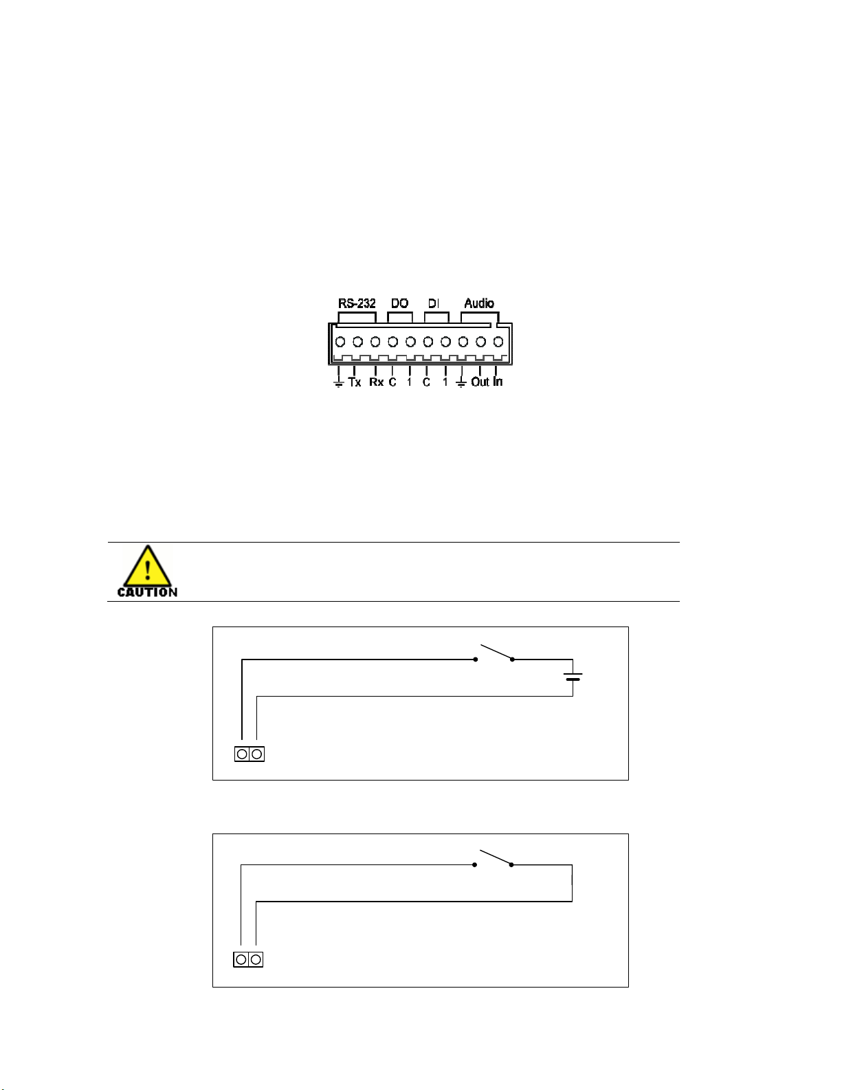
Remote Control: RS-485/RS-422 PTZ Data; Terminal Block
Motion Detection: Supports Multiple Segments per Video
Alarm Functions: Alarm In / Alarm Out - Relay max. 24VAC 500mA or 12VDC 1A (+5V)
USB and micro SD Card: Supports 2.0 (external storage, back-up) / Local Recording
Power Supply: 12VDC, 340mA /Terminal Block; Optional Power over Ethernet
Operating Temperature: 32°F ~ 140°F (0°C ~ 50°C)
Operating Humidity: 0-95% non-condensing
Dimensions L x W x H: 3.7” (94mm) X 2.17” (55mm) X 2.17” (55mm)
Weight: 2.2 lbs. (1Kg)
Material: Die Cast Aluminum
Regulatory Compliance: CE, FCC, ROHS
Manufactured to: ISO9001:2000 Standards

3. Installation & Configuration
3.1. Packag Cont nts
The Package contains the following. Please make sure all listed items are included
in the box.
DN112 ------------------------------------------------ 1
12VDC Adaptor --------------------------------------1
LAN Cable (Cross Type 1.5m) ------------------------1
10 Pin Terminal Block ---------------------------------1
Mount ring for lens ---------------------------------- -1
0.9 mm hex wrench ----------------------------------1
Rubber cap for protecting CCD -----------------------1
3.2. Basic Conn ction
Sensor
Siren
Flashing Light
Analog Monitor
MIC
Amp Speaker
MIC4DVR
Alarm Input
Up to 1
DC 12V
Power supply
Alarm Output
Up to 1
Client PC
Ethernet Network
DC 12V
Power supply
DC 12V
Power supply
Figure 1. Basic Installation Configuration

3.3. Functions
ETHERNET
Micro SD
RS-232 DO DI AUDIO
RESET
Tx Rx C1C1Out In
LOOP OUT
Bottom view
Figure 2. DN112
1 2 3
5
7
9
4
8
10
Rear panel view

1 Vid o Output
BNC video output port
2 R s t Switch (R s t)
Reset switch is used for restarting DN112 or resetting DN112 as Factory Default
(FD). Refer to ‘4.1. Factory Default Settings’ for detailed procedures.
3 USB conn ctor
USB connector is used for connecting the USB device with DN112 .
4 10 pin t rminal block for D/I, D/O and s rial communication – n w v rsion
will b RS-422/RS-485
Figure 3. 10 pin terminal block
D/I – Alarm Input
DN112 provides 1 channel D/I (Alarm Input). It may be connected to either
voltage type sensor or relay type sensor as following Figure 4 and Figure 5. It
may be selected by software.
Please pay attention to electric characteristics during installation.
C1
+5V
Figure 4. Voltage Type Digital Input Connection
C1
Figure 5. Relay Type Digital Input Connection

D/O – Alarm Output
DN112 provides 1 channel D/O (Alarm Output). It may be connected to either
voltage type sensor or relay type sensor as following Figure .
C1
+5V
Figure . Digital Output Connection
Please pay attention to electric characteristics during installation.
RS-232C – will b r plac d by RS-422/RS-485
RS-232C (new RS-422/RS-485) Terminal Block is used for some devices such as
POS terminal block.
RX
<RS- 232C Applic ation>
TX GND
RX
TX
GND
TX
RX
GND
Figure 7. RS-232C (new RS-422/RS-485) Connection
5 Four (4) pin conn ctor for audio In / Out
DN112 has a mono audio input and a mono audio output. As the output power
for the audio is low, amplifier speaker is needed (Do not use a headphone or
earphone directly connected into the camera).
Figure 8. 3 pin connector for audio in and out.
A out
A in
Mic
Amp Speaker

Pow r Adaptor Conn ctor (12VDC)
DN112 employs a 12VDC power supply.
Figure 9. Power Terminal
7 Micro SD Card sock t
DN112 features a memory card slot for external storage.
8 LAN Conn ctor (Eth rn t)
This is a RJ-45 LAN connector for 10/100 Base-T Ethernet.
Figure 10. RJ-45 LAN connector
9 Four (4) pin conn ctor for IRIS
Figure 11. 4 pin connector for IRIS
Only DC-drive type is supported. If User selects DC-drive type of auto IRIS lens,
set ELC/ALC (A.I./E.E.) to the ALC (A.I.) position.
PIN DC IRIS Lens
1 Damp-
2 Damp+
3 Drive+_
4 Drive-
Table 1. Pin description for IRIS
2
1
4
3
+
-
Status LED Network LED

10 Adaptor for mounting th cam ra
Mounting adapter is provided on the bottom of the camera for mounting the
camera on a bracket or tripod. Adapter is designed to accept standard size
mounting screws. It may be unfastened and the mounted onto the top side of the
camera, depending on User application.
Caution: Th mounting brack t must b capabl of supporting th w ight of
th cam ra and its l ns.
3.4. L ns Installation
CCW
CW
SET SCREW
Figure 3. Lens installation
3.4.1. Installing C/CS Mount l ns
1. Remove the protective rubber cap from the front of the camera
2. Install the mount ring for lens and adjust the mount ring to fit C or CS lens.
3. Tighten the setscrews using hex wrench provided in the package.
3.4.2. Installing an Auto IRIS l ns
1. Remove the cover of the auto iris lens plug and connect it with the lens cable.
2. Connect the auto iris lens plug to the 4-pin lens terminal on the side of the
camera.
3. Move to EE mode switch to ALC mode.
4. Adjust to the DC LEVEL carefully to avoid hunting
Note: Use the connection recommended by the manufacturer. For best practices,
read the lens manual carefully. User may need to set the flange back focus.
CCW
CW
SET SCREW

3.5. S rial Numb r / MAC Addr ss
Serial number and MAC address is attached on the bottom of DN112 as shown
in Figure 4.
Figure 4. Serial Number / MAC Address
710030FFD
DN1125
MAC 00:13:23:03:0F:FD
P140101010000 - 14001
Serial Number
MAC Address

4. Op ration D scription
4.1. Factory D fault S ttings
Factory default settings are set as follows:
• IP address: 192.1 8.xx.yy (refer to 2.3 Serial Number / MAC Address)
• Mask: 255.255.0.0
• Gateway: 192.1 8.0.1
• User ID: root
• Password: pass
xx yy xx yy
MAC address = 00-13-23-01-23-45 → IP address = 192.1 8.35. 9
To Convert Hexadecimal numbers to Decimal numbers, use PC calculator.
In Calculator Menu:
1. Click View and select Scientific version
2. Next select Hex to convert digits xx - use keypad input number ex: 23
3. Next select Dec and get result = 35
4. Repeat for digits yy – select Hex, input number ex: 45
5. Next select Dec and get result = 9
To perform the FD (Factory Default) initialization:
1. Turn on the power (The status LED is on).
2. Press and hold the Reset button within 1 second.
3. Release the Reset button after 3 seconds.
4.2. R booting
To reboot the system:
1. While the camera is in use, press and hold the Reset button. (Both Status
and Network LEDs are on.)
2. Release the Reset button after 3 seconds.
Convert the Hexadecimal number to Decimal number

5. Pow r ov r Eth rn t (PoE)
The PoE feature employed in DN112 is available in models DN112 A4 and
DN112 B4. The standard units for power via 12VDC are models DN112 A1
and DN112 B1. For the detailed information, please see Data Sheet on Series
DN112 IP Box Cameras.
5.1. PoE compatibility
With non Power Sourcing Equipment (PSE)
When it is connected with non PSE, the power adaptor should be connected.
With power adaptor
Connecting both PSE and power adaptor does not do any harm to the products.
Disconnecting power adaptor while it is operating does not stop operation. The
product continues to work without rebooting.
5.2. Pow r classification
The PoE Power Class supported by DN112 is Class 0.
Table 2 shows IEEE 802.3af power classes.
Class
Usage Minimum Power Levels
Output at the PSE
Maximum Power Levels at
the Powered Device
0 Default 15.4W 0.44 to 12.95W
1 Optional 4.0W 0.44 to 3.84W
2 Optional 7.0W 3.84 to .49W
3 Optional 15.4W .49 to 12.95W
4 Reserved for Future
Use
Treat as Class 0 Reserved for Future Use
Table 2. IEEE 802.3af PSE and Powered Device Power Classifications

6. El ctrical Charact ristics
6.1. Op rating conditions
Parameters Min Typical Max Units
Audio input range 0.01 2.593 3.3 Vp-p
Ambient Operating Temperature 0 - 55 ºC
Ambient Operating Humidity 85 - 95 %
Table 3. Operating conditions
6.2. Pow r consumption
DN112
Input Voltage 12VDC
Current 120-240VAC
Consumption 240mA
Table 4. Power consumption
O er oltage and o ercurrent will cause a se ere damage to the de ice or e en
a fire.

7. Dim nsions
(Unit: mm)
R vision history
MANUAL#
DATE(M/D/Y)
COMMENTS
D1A.01 02/09/09 Created
D1A.02 02/11/09 Review and correct the error data
94.2
91.
55
55
This manual suits for next models
4
Table of contents
Other Dante Security Camera manuals

Dante
Dante DLV1329A21V User manual

Dante
Dante DLM1971 User manual

Dante
Dante DNA1991YM User manual

Dante
Dante DNA1425T User manual

Dante
Dante DLM1772(Y) User manual

Dante
Dante DLS1621A51 User manual

Dante
Dante DN1125A4 User manual

Dante
Dante DNA1355V User manual

Dante
Dante DLV1331WA35-21V User manual

Dante
Dante DLF1329WPV User manual

Dante
Dante DLS1798LA3Q9 User manual

Dante
Dante DLM1762 User manual

Dante
Dante DLF1330A User manual

Dante
Dante DLF1323AP User manual

Dante
Dante DLF1129P User manual

Dante
Dante DLC1981 User manual

Dante
Dante DLV1420W User manual

Dante
Dante DLF1328A User manual

Dante
Dante DNA1982 User manual

Dante
Dante DLI1972 User manual