a Ensure heat pump on site is as ordered, i.e. model, electrical supply and
factory fitted options.
b Inspect unit for damage, in particular inspect e evaporator (finned side)
to ensure at it is undamaged. (Minor indentations in e fins do not affect
performance). If severely damaged, endorse delivery note in presence of e
driver and send a recorded delivery letter to transport company giving details.
c Protect unit if installation is delayed.
d Provide a firm level base capable of supporting operational weight of unit;
spread load on timber floor.
e Ensure water cannot collect under unit - recommend units are installed on
plins 100mm above finished floor level and to also aid condensate drainage.
f Allow adequate clearance to service panels on unit; recommend 500mm
minimum (see installation drawings).
g All Calorex heat pumps are by design as quiet as is practical, however due
consideration should be given to siting in order to fully exploit is feature, i.e.
orientate inlet/outlet parallel to occupied premises.
h Ensure loose debris such as leaves, grass cuttings, etc will not block air inlet
grilles.
i Consider protection from extreme weaer conditions if installed externally, i.e.
lean-to-cover or building.
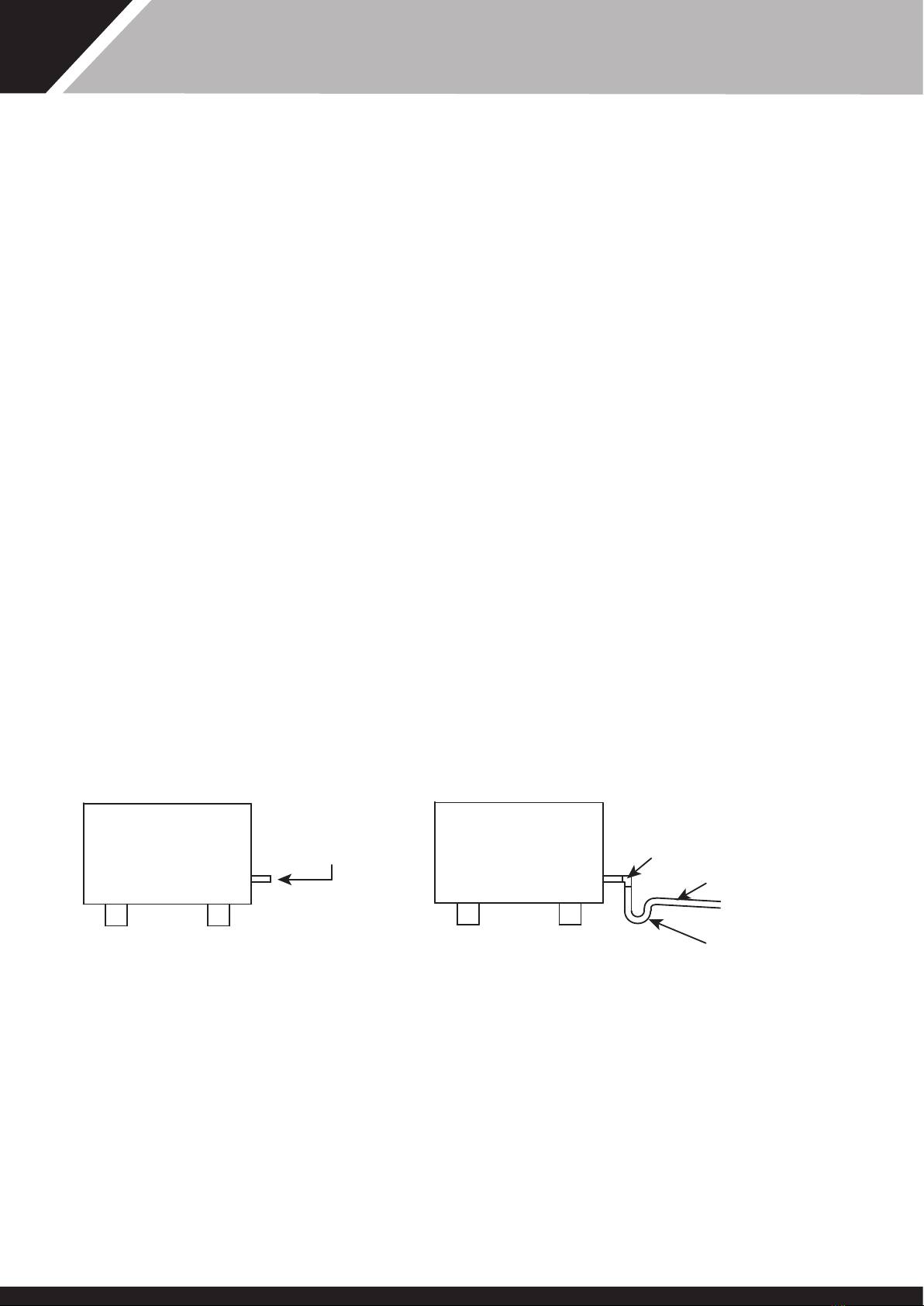
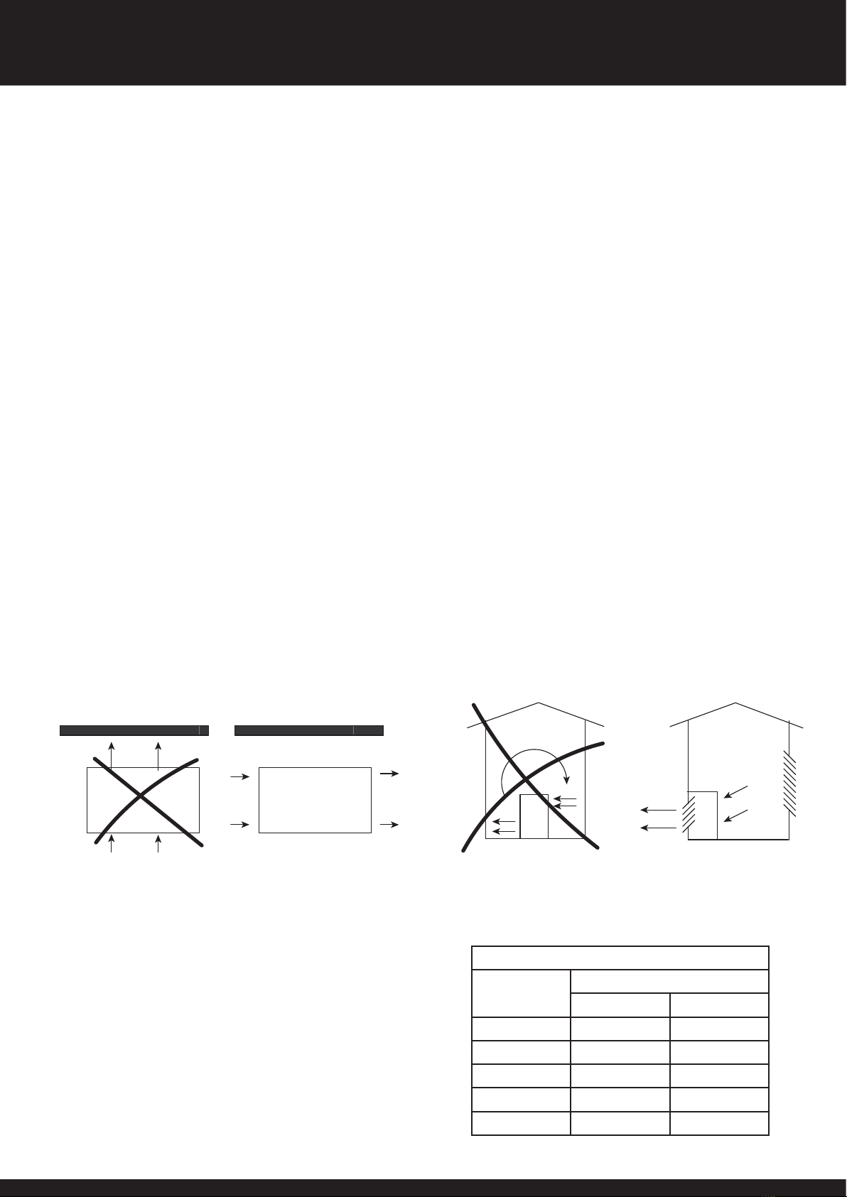
Due consideration must be given to air flow, i.e. do not obstruct inlet or outlet
and ensure discharge air cannot recirculate to inlet. (See figures 1 and 2)
Required Free Areas to provide air flow to and from heat pumps when
installed in an enclosed area or where required to pass air rough a
wall, etc.
Free area is e available area rough which air can pass rough a grille or
louvres.
1. Note: If multiple units are installed in an enclosed area en e inlet free
areas required for each unit can be added togeer to form one inlet aperture.
BUT discharge from each unit must be kept separate and must not be
incorporated into one common duct system.
2. If e unit is installed wiin a plantroom, connected to ductwork, Danerm
Ltd. can supply e unit wi an uprated fan motor.
Please consult Danerm Ltd. before ordering a unit.
INSTALLATION
1. SITING
TYPICAL OUTSIDE INSTALLATION
FIGURE 1
WALL, FENCE OR HEDGE
TYPICAL INSIDE OR PLANTROOM INSTALLATION
FIGURE 2
WRONG RIGHT
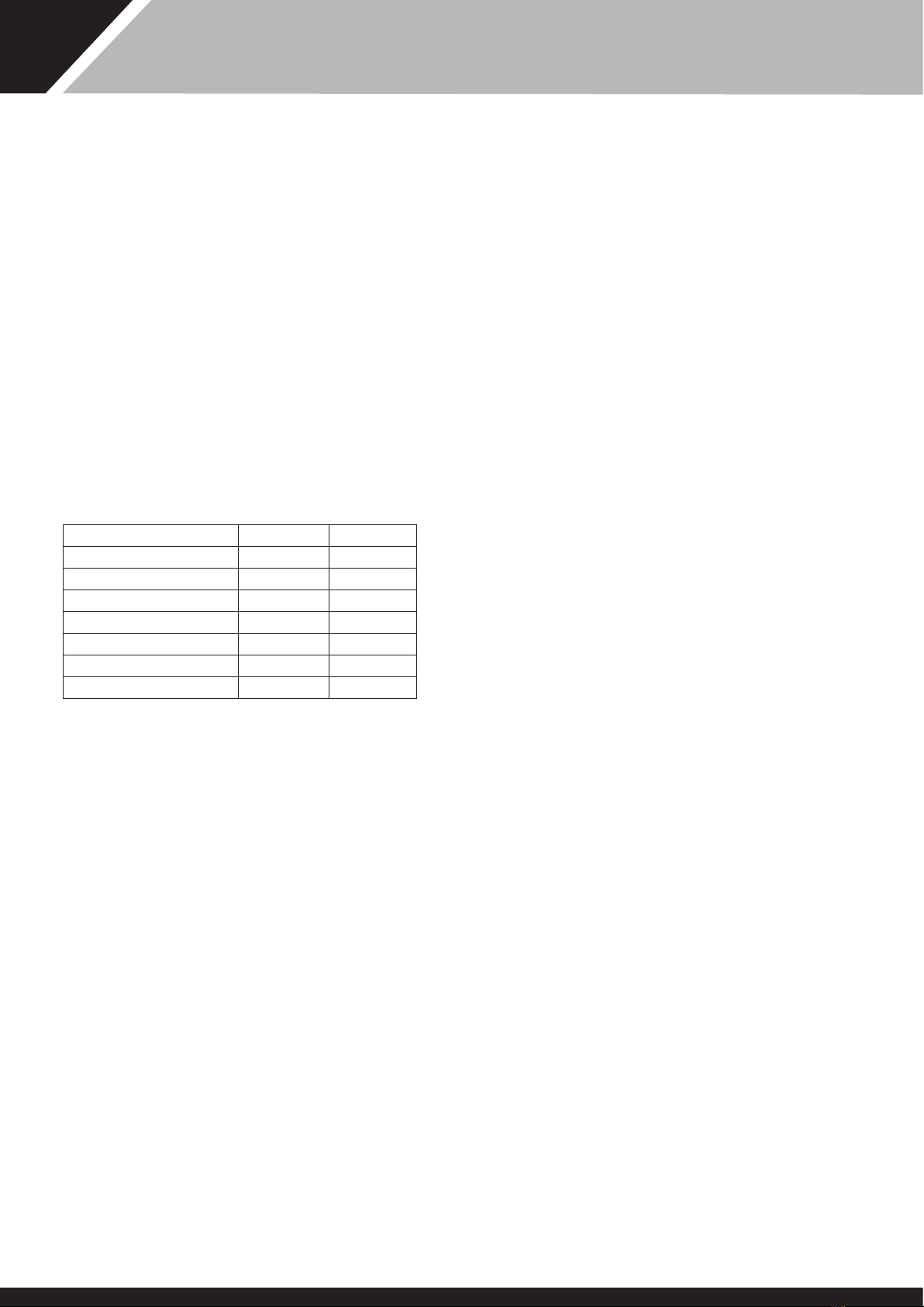
Grill or apertures MUST comply wi figures (see Table 1)
TABLE 1
MODEL MINIMUM FREE AREA M2
INLET DISCHARGE
AW834 0.46 0.06
AW1234 0.46 0.07
AW1534 0.54 0.10
AW3034 1.2 0.18
AW7034 1.5 0.2
2. AIR FLOW
6 SD331851 ISSUE 28
AW834,1234AH/BH,1534BH AW 3034,7034H/HY OWNER INSTALLATION MANUAL