manuals.online logo
Brands
  1. Home
  2. •
  3. Brands
  4. •
  5. Lennox
  6. •
  7. Heat Pump
  8. •
  9. Lennox G21 Series User manual

Lennox G21 Series User manual

GAS UNITS
KITS AND ACCESSORIES
@1997 Lennox Industries Inc, 503,289M
Dallas, Texas 2/97
Supersedes 7/96
_j_ Technical
_L Publications
Utho U.S.A,
HEAT CABLE KIT
INSTALLATION INSTRUCTIONS FOR HEAT CABLE KIT (LB--88643A, B & C) USED
WITH G21, GSR21, G26, GHR26 AND COMPLETEHEAT SERIES UNITS
Package 1 of 1contains:
1 - - Heat cable
Heat cable kit protects drip leg assembly, condensate
line, flue pipe and vent terminations when the unit is
installed in unconditioned spaces where freezing is
possible. When installed as outlined in manufacturer's
instructions, the heat cable will protect PVC and CPVC
lines from freezing without causing damage to pipes. The
heat cable is 120VAC pro-assembled self-regulating
electric cable. There are three heat cable kits available in
6 ft., 24 ft. and 50 ft. lengths (excluding 30" long cord set).
Fiberglass and aluminum tape are needed for each
installation. Table 1 lists all kits available from Lennox.
TABLE 1
DESCRIPTION LB--NUMBER CAT, NUMBER
6F]_ HEAT CABLE KIT LB- -88643A 26K68
24 FT HEAT CABLE KIT LB- -88643B 26K69
50 FT HEAT CABLE KIT LB- -88643C 26K70
66 FT FIBERGLASS TAPE KIT LB--56532DA 39G04
60 FT ALUMINUM FOILTAPE KIT LB--56534DA 39G03
NOTE - - Before installing heat cable kit, installer must
provide a 120V power source with cithara circuit breaker
or fuse suitable for handling required cable length. Do
not use an extension cord to reach the receptacle. For
additional safe_ a ground-fault pretection device should
be installed. See heat cable manufacturer's installation
instructions.
See table 2 to determine the length of heat cable needed
for specific run of PVC or CPVC pipe.
TABLE 2
LENGTH OF PIPE COVERED FOR
LENGTH OF HEAT CABLE
PIPE SIZE 6 FT. 12 F3_ 18 FT. 24 FT. 50 FT. 100 FT.
O.SlN. I 6 I 12 I 18 I 24 I 50 I 100
RUN CABLE STRAIGHT tl FT OF CABLE TO 1 F_ OF PIPE_
_nIN I 3 I6IgI_I _s Isn
SPIRALCABLE(2 F]_OFCABLETO1FT OFPIPE.)
3nIN I _ I4IRIRI1_7 I:_33
SPIRALCABLE(3 FI_OFCABLETO1FT OFPIPE.)
Table 2 assumes lowest outside temperature of 0°F with
a minimum of 1/2" fiberglass insulation or equivalent (i.e.
Armaflex.) For protection to --20°F, use 1" fiberglass
insulation or equivalent. Multiple heat cable may be
needed for longer runs of pipe.
1 - -The first 30" from plug end of the heat cable is the
cord set. This section does not get hot and should
not be wound around the pipe. To prevent damage
to the cord set, provide a strain relief using plastic
cable ties, or three thicknesses of either, vinyl, glass
cloth or heavy duct tape.
2--Wrap heat cable around pipe, condensate trap
assembly or vent termination, so that the cable is
pulled tight to ensure continuous contact between
the cable and the pipe. See figure 1.
Side View
If heat cable is longer than pipe, spiral
cable evenly along pipe and according toT able 2.
Side View End View
If pipe is 0.5" condensate pipe, cable of same length may be
run straight along pipe in either the 4 or 8 o'clock position.
FIGURE 1
3 - - After wrapping heat cable around pipe, secure cable
to the pipe using fiberglass tape. Wrap tape around
the pipe and cable using approximately 1-1/2 wraps
every foot. See figure 2. Do not use electrician's
tape, duct tape, vinyl tape, metal clamps or any
wire. Heat from the cable breaks down adhesive
properties of these tapes.
HEAT CABLE ALUMINUM FOIL TAPE
•,,'-',_1_ ' '/•......_I INSULATION
?,,J'
PVC or CPVC \
PIPE FIBERGLASS TAPE
(Wrap around pipe 1-1/2 times)
FIGURE 2
Page 1
4--Applyaluminumfoiltapeinlinearstripsoverpipeand
cable.Do not spiral wrap foil tape over pipe. tt may
be necessary to fold one strip up from the bottom and
one strip down from the top of the pipe to ensure
complete coverage. See figure 2.
5--Insulate pipe using fiberglass insulation or
equivalent, i.e. Armaflex. For protection to 0°F use
minimum of 1/2" fiberglass insulation or equivalent
(i.e. Armaflex.) For protection to --20°F, use 1"
fiberglass insulation or equivalent. For protection to
--40° F,use 1-1/2" fiberglass insulation or equivalent.
See figure 2.
6--Use waterproofing materials such as polyethylene
sheets or other vapor barriers to protect insulation in
areas exposed to moisture (vent termination).
7 - - Refer to figure 3 for G21 condensate trap assembl
G21 CONDENSATE TRAP ASSEMBLY
HEAT CABLE
TRAP
FIBERGLASS
TAPE
*Heat cable can be run
straight on 0.5" condensate
line. See table 2.
DO NOT BLOCK
CLEAN-OUT PLUG
START OF
CORDSET
FIGURE 3
8 - -Two methods may be used to apply the heat cable to
concentric vent terminations. See figures 4 and 5.
Figure 4 shows wrapping the heat cable around a
concentric vent termination that has already been
installed. The 24ff. heat cable is recommended for
this method.
CONCENTRIC WALL
TERMINATION APPLICATIONS
EXHAUST CLAMP
\FIBERGLASS
TAPE "_l_
INTAKE
EXHAUST
FLUE/
CAP
FIGURE 4
9--Figure 5 shows wrapping a concentric vent
termination before it has been installed. The 6 ft.
I
cable is sufficient for this method. If allowable, this
method is recommended over the first method
because it provides better flue pipe protection.
NOTE-- The waft or roof hole may need to be
enlarged to provide enough clearance for the heat
cable and insulation. The heat cable can be installed
over the mounting clamp or the clamp can be opened
up to provide enough clearance for the heat cable
and insulation.
IMPORTANT J
Drill 1/2" dia. hole in rain shield
HEAT CABLE for cable. Seal hole after running
1-1/2"
__ heat cable Jr.
through
EXHAUST
Dr,,,/2"dia.he,oi°iow,°OO°te,Sg°
from air intake connection. Seal hole l /
after running heat cable through it. RAIN /
i .o
FIBERGLASS
_/_F-_ AIR INTAKE
FIGURE 5
10- -For the HM30 module of the CompleteHeat system,
spiral wrap the flue trap twice with heat cable before
wrapping the condensate line. See figure 6. Enlarge
condensate line cabinet hole to allow for heat cable
and insulation. Make sure there is enough clearance
between heat cable and cabinet. Protective coating
on heat cable must not be damaged. Do not wrap
the flue trap boot.
HM30 FLUE TRAP
FLUE TRAP
CONDENSATE
LINE*
FIBERGLASS
TAPE
i
FLUE TRAP BOOT ," ,!
_IL ..................J*Heat cable can be run
straight on 0.5" condensate
line. See table 2.
FIGURE 6
Page 2
11--FortheG26seriesunits,theheatcableshouldbe
installedon the sameside of the unit as the
condensate.Seefigure7.
Notice -- G26 units have been manufactured with two
exhaust configurations. Early models have a hard plastic
flue °Y°between the combustion air blower and the top
of the unit. Later models have a soft rubber flue transition
between the combustion air blower and the flue collar:
(The later model with the soft rubber flue transition
configuration is shown in figure 7.)
(a) Insert approximately 30 inches of the heat cable
into the cabinet where the condensate drain pipe
exits the unit.
(b & c) Route the cable around the condensate drain
pipe and under and around the condensate boot on
the collector box. Secure with wire tie.
(d) Use wire ties to secure the cable to the
condensate drain.
(e) Units with hard plastic flue °Y°:
Wrap the heating cable around the flue "Y" in the
boot region, since this area holds trapped water.
Secure with a wire tie (field provided). Insulate
around the trap and heat cable.
G26 Right Side Drain
AIR FLOW
Q= Wire Tie
FIGURE 7
11- -For the GHR26 series units, (a) remove the air intake
cabinet plug on the side of the unit which the
condensate trap is installed. See figure 8.
(b) Insert approximately 30 inches of the heat cable
into the cabinet through the air intake pipe hole.
(c & d) Route the cable around the flue collar and
behind and around the condensate drain inside the
cabinet. Use a wire tie (field provided) to secure the
cable to the condensate drain (where the long drain
hose attaches).
(e) Run cable along the long black drain hose to the
collector box. Wire tie (field provided) the cable to the
drain hose where drain attaches to the collector box.
Make sure the heat cable does not cause any dips or
rises in the long black drain tube that would interfere
with the natural flow of condensate.
(f) With remaining length of cable outside of the unit,
make three wra )s around the condensate trap and
secure with a wire tie (field provided). Insulate around
the trap and heat cable.
GHR26 Horizontal Position
Q= Wire Tie
FIGURE 8
Page 3

This manual suits for next models

3

Other Lennox Heat Pump manuals

Lennox SPB036H4 User manual

Lennox

Lennox SPB036H4 User manual

Lennox XP14 Installation and operation manual

Lennox

Lennox XP14 Installation and operation manual

Lennox LHT Series Owner's manual

Lennox

Lennox LHT Series Owner's manual

Lennox T-Class TPA090S4S User manual

Lennox

Lennox T-Class TPA090S4S User manual

Lennox FCM 85 User manual

Lennox

Lennox FCM 85 User manual

Lennox HP29 Series User manual

Lennox

Lennox HP29 Series User manual

Lennox XP17-024-230-01 Manual

Lennox

Lennox XP17-024-230-01 Manual

Lennox 14HPX User manual

Lennox

Lennox 14HPX User manual

Lennox KHA180 User manual

Lennox

Lennox KHA180 User manual

Lennox LCH Series Installation and operation manual

Lennox

Lennox LCH Series Installation and operation manual

Lennox INNOV DM R Series User guide

Lennox

Lennox INNOV DM R Series User guide

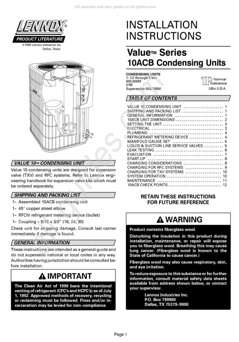
Lennox Value 10ACB Series User manual

Lennox

Lennox Value 10ACB Series User manual

Lennox KHA SERIES User manual

Lennox

Lennox KHA SERIES User manual

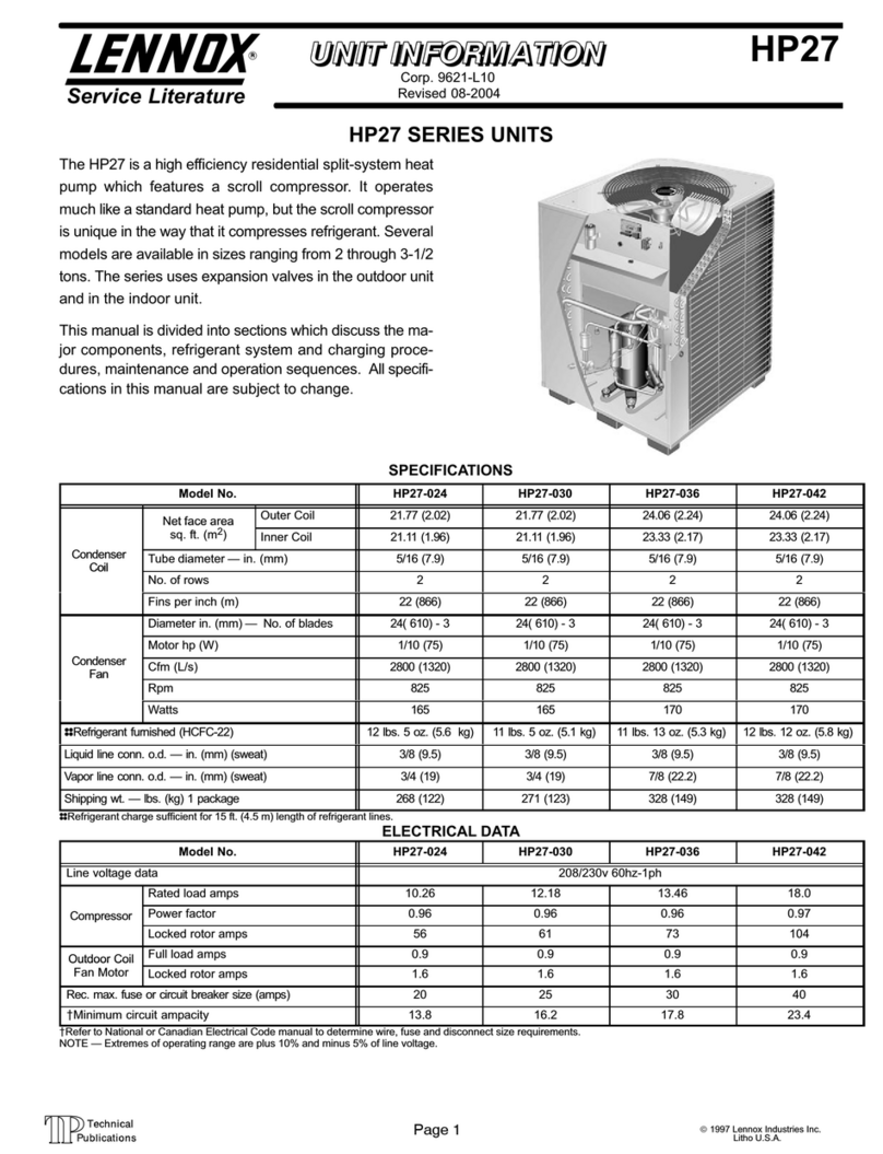
Lennox HP27 SERIES User manual

Lennox

Lennox HP27 SERIES User manual

Lennox ML18XC2 Series User manual

Lennox

Lennox ML18XC2 Series User manual

Lennox ECB38 Series User manual

Lennox

Lennox ECB38 Series User manual

Lennox HP27?024 Installation and operation manual

Lennox

Lennox HP27?024 Installation and operation manual

Lennox 12HPB Series User manual

Lennox

Lennox 12HPB Series User manual

Lennox HPXA15 SERIES Planning guide

Lennox

Lennox HPXA15 SERIES Planning guide

Lennox LRP14G User manual

Lennox

Lennox LRP14G User manual

Lennox 13HPX User manual

Lennox

Lennox 13HPX User manual

Lennox HP29-090 User manual

Lennox

Lennox HP29-090 User manual

Lennox HP40 User manual

Lennox

Lennox HP40 User manual

Lennox Elite XP13-018-230 User manual

Lennox

Lennox Elite XP13-018-230 User manual

Popular Heat Pump manuals by other brands

SPRSUN CGK/C-12 installation manual

SPRSUN

SPRSUN CGK/C-12 installation manual

NorthFlo PSNF50VS manual

NorthFlo

NorthFlo PSNF50VS manual

SILENSYS SILFH4524Z Technical data

SILENSYS

SILENSYS SILFH4524Z Technical data

GeoSmart ECO-Y installation manual

GeoSmart

GeoSmart ECO-Y installation manual

Nortek PSH4BE user manual

Nortek

Nortek PSH4BE user manual

Kensa Heat Pumps Shoebox user manual

Kensa Heat Pumps

Kensa Heat Pumps Shoebox user manual

Tempstar N4H3 installation instructions

Tempstar

Tempstar N4H3 installation instructions

Templari KITA ARIA Installation and maintenance manual

Templari

Templari KITA ARIA Installation and maintenance manual

Dimplex LIK 8ME Installation and operating instructions

Dimplex

Dimplex LIK 8ME Installation and operating instructions

Bulldog Security SKC008 Installation operation & maintenance

Bulldog Security

Bulldog Security SKC008 Installation operation & maintenance

Arbonia DXB Series Installation and maintenance manual

Arbonia

Arbonia DXB Series Installation and maintenance manual

CIAT AQUACIAT POWER ILD Series instruction manual

CIAT

CIAT AQUACIAT POWER ILD Series instruction manual

Trane GEHE 072-180 Installation, operation and maintenance

Trane

Trane GEHE 072-180 Installation, operation and maintenance

American Standard 2A6H3018A Installer's guide

American Standard

American Standard 2A6H3018A Installer's guide

Panasonic WH-UD09CE8 operating instructions

Panasonic

Panasonic WH-UD09CE8 operating instructions

Trane 4TWR5018E Installer's guide

Trane

Trane 4TWR5018E Installer's guide

American Standard 2A7C3000A Installer's guide

American Standard

American Standard 2A7C3000A Installer's guide

WarmFlow G Series manual

WarmFlow

WarmFlow G Series manual

manuals.online logo
manuals.online logoBrands
  • About & Mission
  • Contact us
  • Privacy Policy
  • Terms and Conditions

Copyright 2025 Manuals.Online. All Rights Reserved.