Dare VSRu User manual

2020 V1
ASSEMBLY MANUAL

A
S1
S4
S2
S5
S14
S8
S9
S9
S11
S11
S13
S9
S10
S8
S3
C
E
D
B
F
G
G
H
J
I
K
F
Parts In Exploded View
Carbon fiber parts may be broken because of
excessive locking force. It may generate high
risks and impact the warranty of product.
Please comply the maximum torque limitation
defined in the DARE specification. Moreover,
please use the correct torque wrench to lock
socket set bolts. In addition, commercially
available oils for assembly can be adopted to
increase part adherence in accordance with
actual situations.
To minimize air resistance, VSRu frame is an
internal cable routing model, which means
you must be more careful when assembling.
We highly recommend you complete the bike
fitting and assembly testing in advance.
!
!

F
F1
F2
S8
S9
Front DAC
Disc aero cover
Rear DAC
Flat screw M4*12*8mm
Round screw M4*10*8mm
1
1
1
3
G
G1
G2
G3
S9
S14
Direct mount rear hanger
Hanger
Standard rear hanger
Fork hanger
Flat screw M4*12*8mm
Flat screw M4*8*4mm
1
1
1
1
2
H
H1
H2
H3
H4
FD cable routing
Cable routing
RD Mechanical cable routing
RD Di2 cable routing
Rear brake cable routing
1
1
1
1
S10 Flat screw M5*20*16mm 1
S11 Flat screw M3*8*5mm 1
S11 Flat screw M3*8*5mm 2
I
I1
I2
FD mount
Alloy parts
Seat clamp
1
1
S12 Flat screw M5*20*16mm 2
S13 Round screw M5*14*11mm 5
J
J1
J2
Plastic parts
DI2 RS910 Mount cap
DI2 Battery mount
1
1
J3 Chain catcher 1
S9 Flat screw M4*12*8mm 1
K
K1
K2
Seat post
Seat post
Saddle clamp
1
1
K3 Carbon friction grease 1
A
A1
A2
S2
S3
1
1
2
2
Stem
Stem
Stem front cap
A3 1Stem rear cap
Rear cap flat screw M3*8*5mm
S1
4
Front cap socket screw M5*15*12mm
Clamping socket screw M5*22*18mm
B
B1
B2
S4
1
1
1
Steerer top cap
Steerer
plug expander
Flat screw M6*35*31.5mm
C
C1
C2
C3
1
1
1
Mount bridge
Handle bar extension mount
Computer mount (Garmin system)
Cam/light mount (Go pro system)
S5 1Flat screw M5*16*12mm
S6 2Socket screw M4*13*9.5mm
D
D1
D2
S7
2
1
4
10mm Spacer
Spacer
5mm Spacer
Set Screw M3*5mm
E
E1
E2
E3
1
1
3
Top cap
Headsets
Seal
Washer
E4 1C-ring
E5 11.5” top bearing
E6 11.25” down bearing
List of Assemble parts of frame
S13 S14
S7
S5 S6
S10 S11 S12
S4
A1 A3
F1
F2
J1 J2
J3
A2 S1
B1 C1
C2
D1
E1
E2
E3
E4
G1
H1
I1
I2
K1 K2
K3
H2 H3 H4
G2 G3
S9
S8
E5
E6
D2C3
B2
S2 S3

Mechanical cable guite map
Shifting cable
Bake cable
The mechanical derailleur cable
housing is thicker and harder than
the electronical one. Please practice
the assembly more patiently and
carefully.
Thread the brake hoses to the foam into
the downtube of the frame to avoid the
clacking sounds during riding.
Thread the brake hoses to the foam into the downtube of
the frame to avoid the clacking sounds during riding.
Using Electric system is recom-
mended.
Shimano Di2 cable guite map
Electric wire (EW-SD50 550mm*1 / 950*1 / 250*1 / 350*1 / 650*1)
Brake cable
Y-Electric wire EW-JC130
Wire length Junction B EW-JC200
950mm
250mm
650mm
2XS~S
M~XL 1200mm
550mm
350mm
Junction B SM-JC41
Junction A EW-RS910F
BT-DN110
DI2 WIRE MAP
Battery
BT-DN110
FD
RD
Junction B
SM-JC41
250mm
650mm
900mm / 1200mm
550mm
350mm
Junction B
EW-RS910F
Y-Electric wire
EW-JC130
JC200
! !
! !
(recommend)

G1
G2
D1
D2
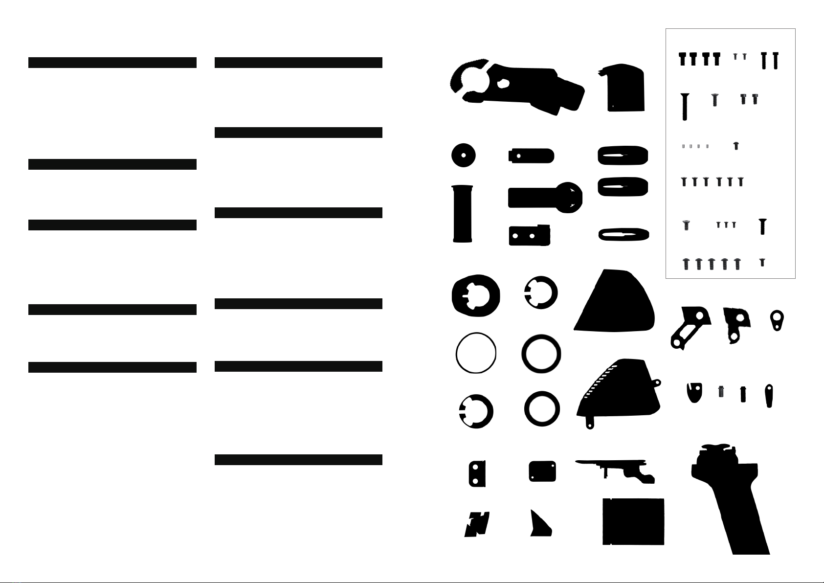
1. Confirm the quantities of headtube spacers
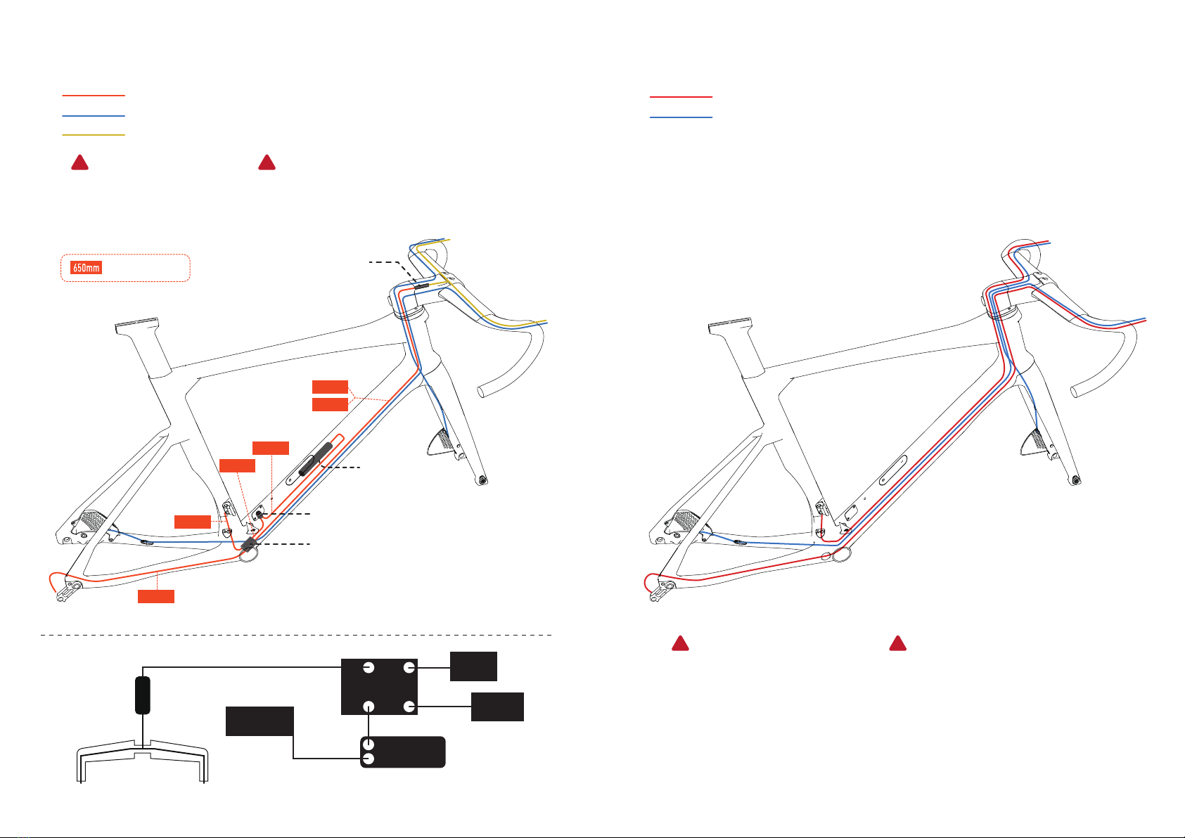
3. Rear cable routing assembly
2. Cutting down the steerer tube
Make sure the exact cable length before assembly (especially mechanical routing), because VETOX is
also an internal cable routing handlebar. Therefore, it is recommended to set your riding position
data in advance that allows to cut your steerer tube length correctly and know the exact spacers you
need (10mm*2 and 5mm*1 spacers attached in the boxes). Below are 3 methods for your references:
1.Referring to the data of your previous bike
2.Consulting to bike fitting service
3.Pre-assembling the VSRu frame, fork, stem, handlebar, saddle and wheelset and adjust to the
proper STW.
After pre-assembling the headset, top cap, spacers and stem, marking the first line on the top of
the stem onto the steerer tube. Then mark the second line, 7~8mm lower than the first one, which
is a space preserved for tightened the top cap later. Align the second line and cut it off.
Thread the rear brake/ shifting cable from the rear of chain stay into the frame. Select the proper
cable-routing ports and hangers in terms of the gear shifting system.
G
J
F
SIZE A B C D E F G H I J
480
500
520
540
560
580
XXS
XS
S
M
L
XL
508
526
543
562
579
597
97
116
137
158
181
201
71
71.5
72
72
72.5
72.5
74
74
74
74
74
74
75
75
73
73
70
70
365
377
389
401
413
425
500
520
540
560
580
600
L
370
370
370
370
370
370
K
736
756
778
798
821
841
410
410
410
410
410
410
967
982
997
1015
1030
1048
C
L
E
I
H
K
D
A
B
8mm
10mm spacer*2
5mm spacer *1
Standard rear hanger
Direct mount rear hanger
( For SHIMANO)
RD Mechanical cable routing
RD Di2 cable routing
H3
H2
S9
2.5mm
2Nm
Additional reference: STW = STACK/REACH
Casual Competitive
Stack/Reach > 1.5 Stack/Reach <1.5
* Picture example: 10mm*2 and 5mm*1 spacers

S9
S14
S8
E6
J2
4. Front cable routing assembly
Thread the brake hoses to the foam into the down tube of the frame to avoid the clacking noisy
sounds during riding.
For Di2 system, use F type of RS-910, which has its mount cap be able to fit on the downtube.
Also, install battery in with a J2 battery mount cover on it.
Foam Tube
*Picture example: DI2 system 2.5mm
2Nm
2.5mm
2Nm
Put the down bearing (E6) first and thread the front brake cable through the inside fork to the
steerer tube. And then install the fork to the frame.
Be aware that the fork might be hit by the
headtube and scratched because of
over-rotating.
EW-RS910-F
!

S3
D3
D2
E1
E2
E3
E4
E5
S4
B1
7. Cable in handle bar
5.Handlebar and stem assembly
6.Integrated headset/ stem cable routing
*picture example:Di2 system
Front brake
Rear brake
DI2 wire
4mm
5Nm
6mm
9Nm
After installing the fork to the head tube, then install the headsets (E1-E5), spacers(D2-D3), and
stem (A1) by orders. (see more detail picture at step.6). Put the compression plug in the steerer
tube and screw the steerer top cap (B1). And then assemble the VETOX handlebar on the stem.
Through the all cable into the channel of headsets and spacers, put into the rear channel of stem
and throughout the hole of stem left and right ( left is front cable, right is rear cable)
Route the cables by following the picture shown below. (Front cable to the left and rear is right)
4mm
SHIMANO Di2 System
Mechanical system
Front brake rear brake
Front brake
Front shift rear shift
rear brake
Please practice the assembly more patiently and carefully. Especially use mechanical system.
S1
S1
A3
4mm
5Nm
B2
Y-Electric wire
!

S3
A2
C1
C2
C3
S5
8. Finishing touches 9. Seat post assembly
After the cable routing, screw the stem rear cover (A2) and complete the final step of
assembly.
Apply Carbon friction grease (K3) to the surface of seat post to avoid clenching with the frame.
Put the hidden seat clamp (I2) into the frame first, then install the seat post. Use the 4-millimeter
Allen key to tighten it from the screw hole hidden below the top tube.
There are two seat post length attached base on the size of frame (see below table). If you want
to change to another size, please contact your local dealer).
VSRu seat post allows 73~74.5 degree of adjustable range. Also, there are an option of shorter
range version for pursuing more aerodynamic look.
Extension mount is attached for installing Garmin and Gopro on VETOX handlebar. It
also applies to general bike computer, camera, and light.
2mm
1Nm
3mm
2.5Nm
VSRu seat post length (mm)
2XS
250 250 300 300 300 300
Frame size
Seat post
standard length
185175 200 220 230 270
Maximum insert
XS S M L XL
maximum
insert
90mm
minimum
insert 4mm
5Nm
DAP02-A
(standard)
DAP02-B
(additional option)
73 74.5
K1
I2
!Please be aware of the depth of inserting the seatpost when you purchase a smaller size
of frame.

Bottle cage screw
TORQUE VALUE RECOMMENTED
3~4 Nm
Cable guide screw
Frame
1.5 Nm
Chain catcher screw 1.5 Nm
FD hanger screw 3Nm
RD hanger screw 3Nm
Seat post clamp screw 5Nm
Saddle clamp screw 12 Nm
Front cap screw 5Nm
Lateral fork screw 4.5 Nm
Seat clamp
seat post
Stem
!
Suggested torque value is applicable under most circumstances. Since such
information is not specified by DARE, please refer to the sign on the bike or the
gadget instruction manuals for details.
Table of contents
Other Dare Bicycle manuals