Darfon B09ULF User manual

INSTALLATION MANUAL
B09ULF LITHIUM BATTERY

I N S T A L L A T I O N M A N U A L B 0 9 U L F L I T H I U M B A T T E RY
R e v . 1 © 2 0 1 9 D a r f o n E l e c t r o n i c s Co r p . P a g e 2o f 28
TABLE OF CONTENTS
1Overview ......................................................................................................................................................................................................................3
2Safety Precautions.....................................................................................................................................................................................................4
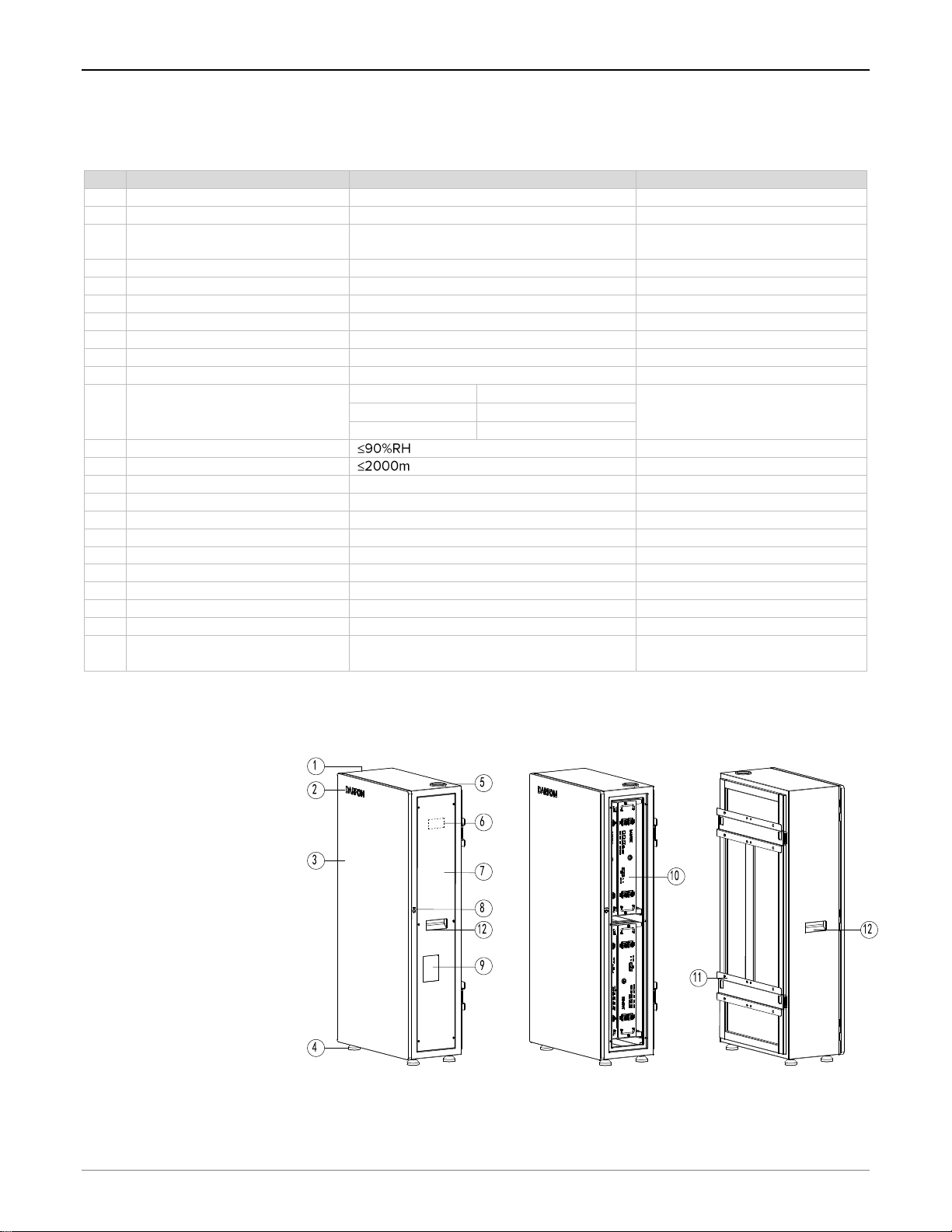
3Identifications..............................................................................................................................................................................................................5
4Product Specifications..............................................................................................................................................................................................6
4.1 System Technical Parameters.....................................................................................................................................................................6
4.2Overall Dimensions and Construction ................................................................................................................................................6
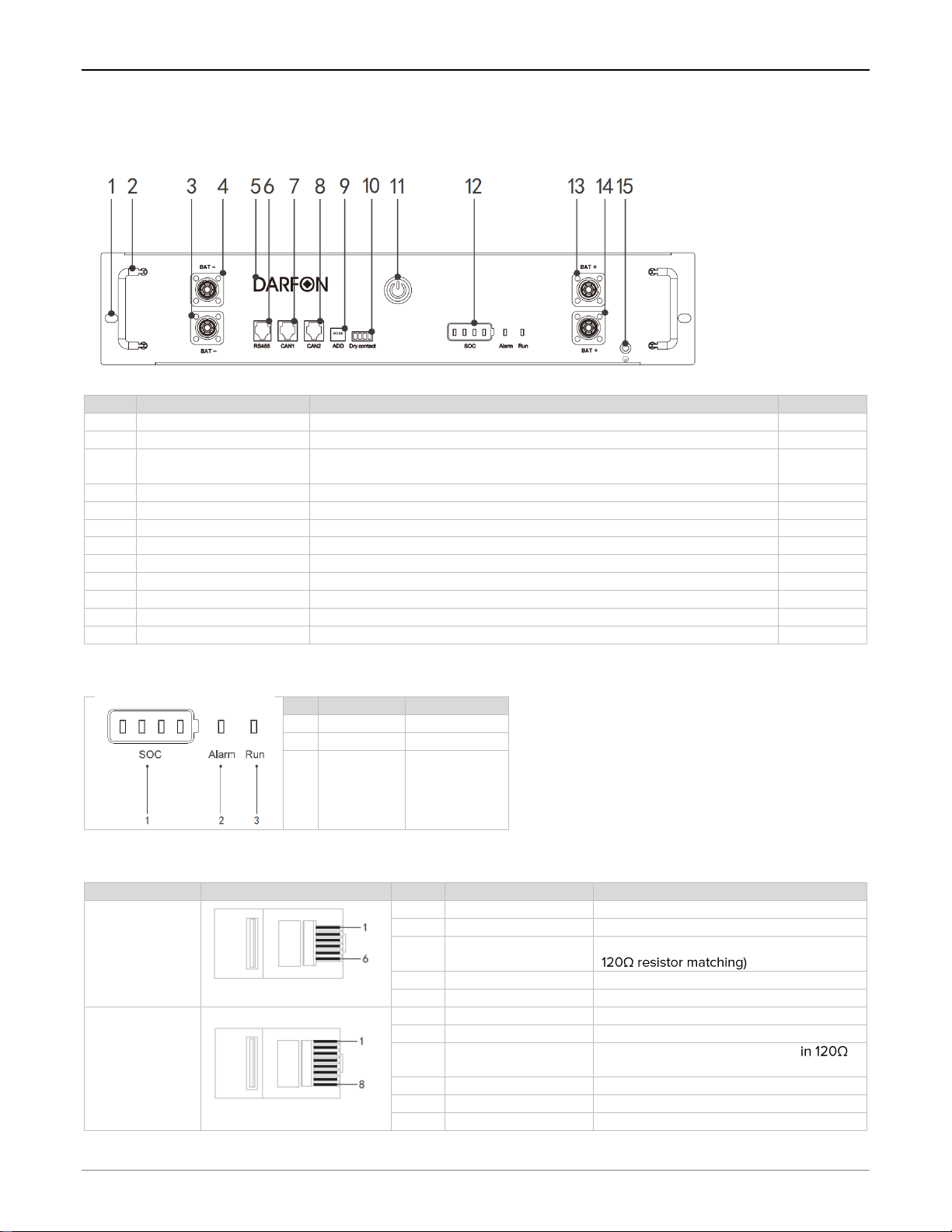
4.3 Battery Modules..........................................................................................................................................................................................7
5Product Installation....................................................................................................................................................................................................9
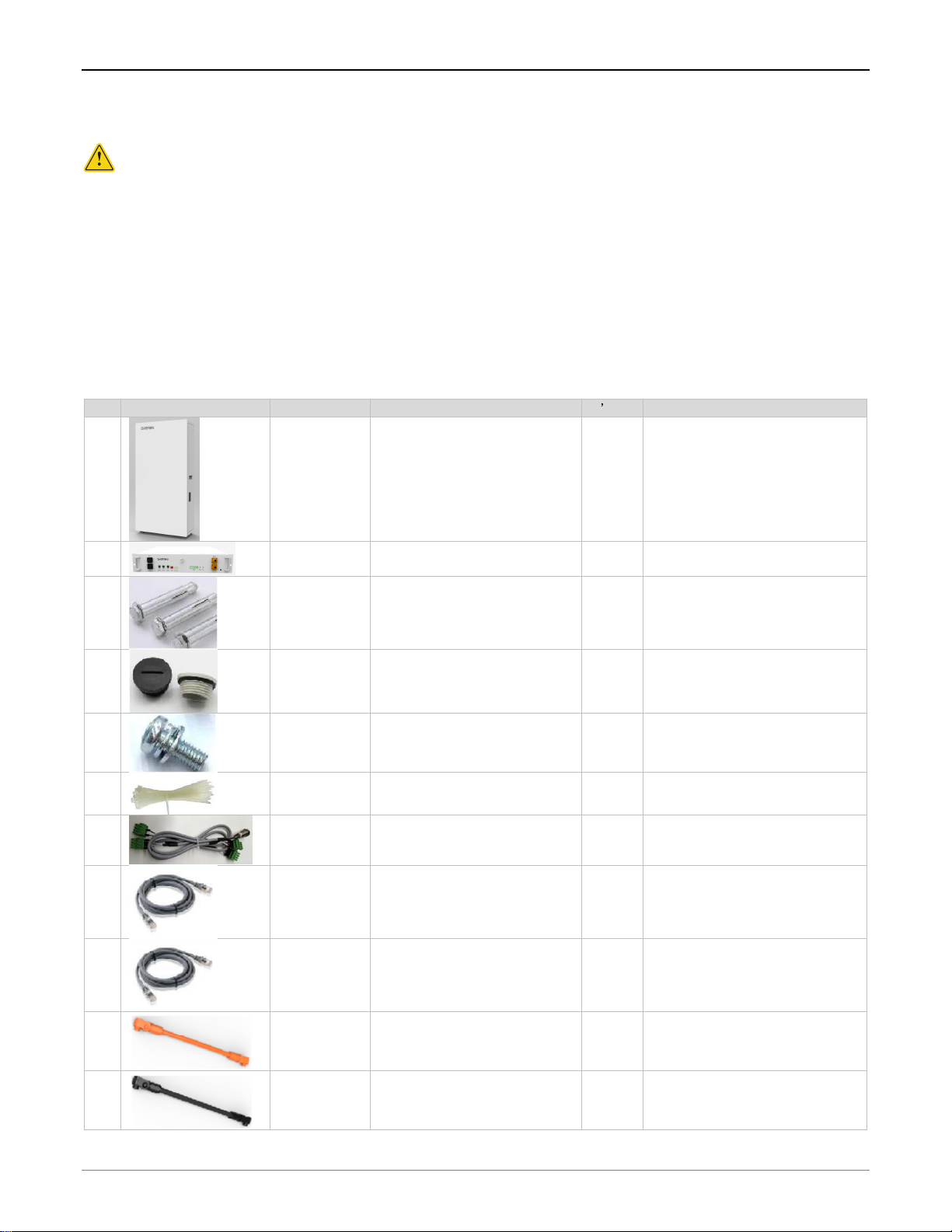
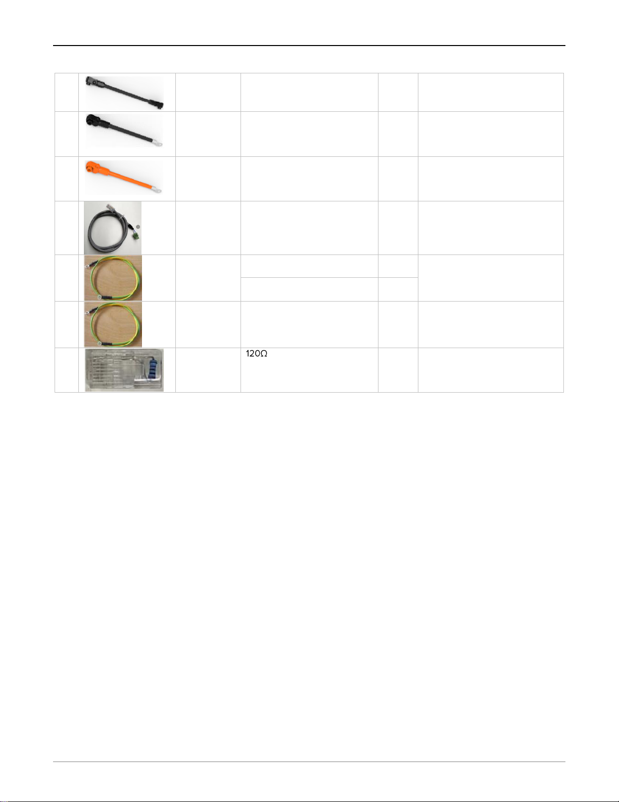
5.1 Device list..........................................................................................................................................................................................................9
5.2 Before installation.....................................................................................................................................................................................11
5.3 System installation...................................................................................................................................................................................12
6Electrical Connection...............................................................................................................................................................................................17
6.1 System Wiring.................................................................................................................................................................................................17
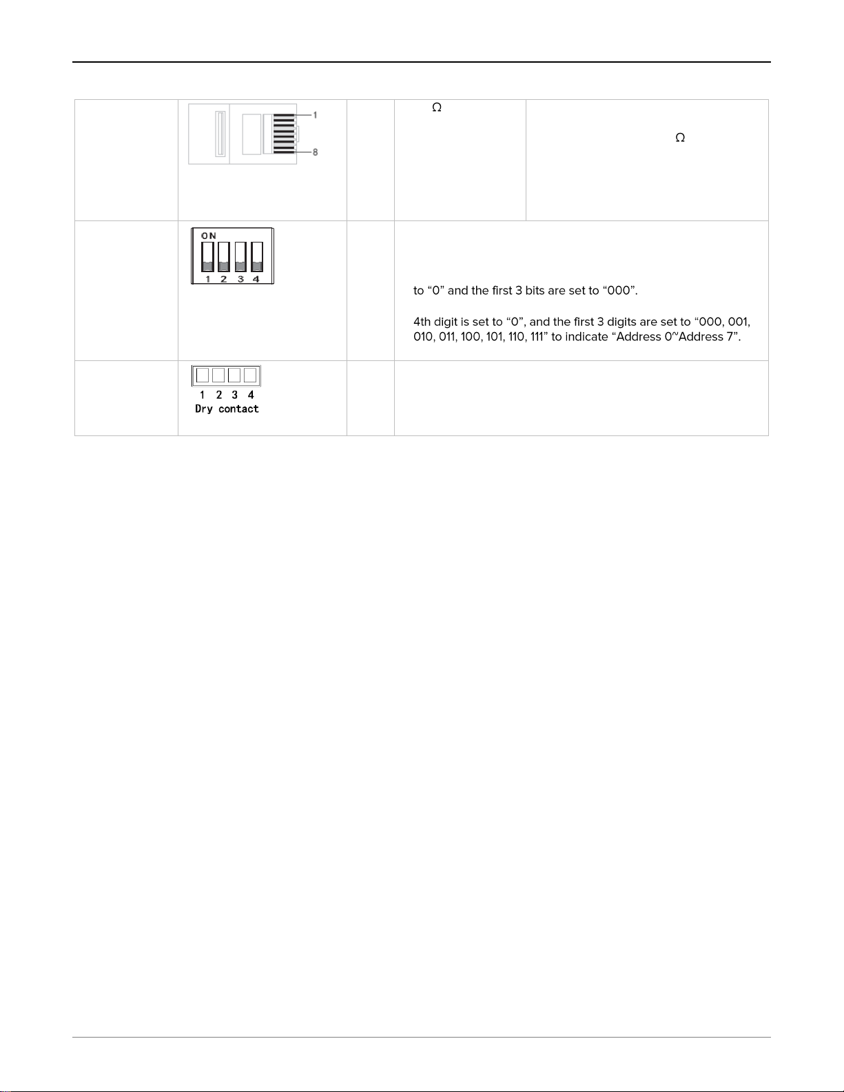
6.2 DIP switch settings..................................................................................................................................................................................20
6.3 Grounding...................................................................................................................................................................................................21
7OperationS.................................................................................................................................................................................................................22
7.1 Power On or Off............................................................................................................................................................................................22
7.2 Display state .............................................................................................................................................................................................22
7.3 Host computer description...................................................................................................................................................................23
8Maintenance and Common Troubleshooting..................................................................................................................................................26
8.1 Daily maintenance........................................................................................................................................................................................26
8.2 Common troubleshooting table..........................................................................................................................................................26
9Packaging, Transportation, and Storage...........................................................................................................................................................27
9.1 System packaging........................................................................................................................................................................................27
9.2 System handling and transportation..................................................................................................................................................27
9.3 System storage........................................................................................................................................................................................27

I N S T A L L A T I O N M A N U A L B 0 9 U L F L I T H I U M B A T T E RY
R e v . 1 © 2 0 1 9 D a r f o n E l e c t r o n i c s Co r p . P a g e 3o f 28
1OVERVIEW
Thank you for choosing the 48V/9.6KWh lithium battery system. The battery system is based on a lithium ferrite phosphate
chemistry and adopts a modular parallel design. Main features are:
•Mainly consists of one cabinet and multiple battery modules.
•The single cabinet supports up to four 48V/50Ah battery modules in parallel.
•Supports up to two cabinets in parallel and can be expanded to 19.2KWh.
•Customized battery management system (BMS), real-time data acquisition, status monitoring and control to ensure safe and
reliable operation of the system.
The system allows flexibility in configuration, which can be widely
applied to household energy storage scenarios.
Architecture of the battery system is shown on the diagram here.
One battery cabinet can house up to 4 battery modules. Two battery
cabinets can house up to 8 modules, and so on.
Battery modules inside each cabinet are connected in parallel. CAN
BUS communication is made between the modules.
RS485 communication is provided for remote monitoring of the
battery modules by an external energy management system.
( ------- Dotted line means optional)
This manual focuses on the safe operation of the system. Please read
this manual carefully before proceeding. If you encounter any problems during the operation of the device, please consult the
corresponding instructions to solve most problems in the installation and operation. Contact your dealer or supplier if necessary.

I N S T A L L A T I O N M A N U A L B 0 9 U L F L I T H I U M B A T T E RY
R e v . 1 © 2 0 1 9 D a r f o n E l e c t r o n i c s Co r p . P a g e 4o f 28
2SAFETY PRECAUTIONS
DANGER
ATTENTION
•Wiring work must be performed by electrical engineers, otherwise
there is danger of electric shock or damage to the system.
•Before wiring, make sure that the power is off, otherwise there is
danger of electric shock or fire.
•The installed cable must meet the requirements, and the power
distribution part must comply with the safety regulations.
•Installation must be carried out in strict accordance with the
following installation steps, otherwise it will cause product damage.
•During normal operation, it is strictly forbidden to directly touch the
terminals such as output and input to avoid electric shock hazard.
•Do not open the casing of the machine directly during normal
operation, otherwise it may cause electric shock.
•When removing the outer casing, be sure to disconnect the input
and output circuits, otherwise there is danger of electric shock.
•Even if the casing is disassembled, there is still residual power
inside the machine. Do not touch the bare part of the line directly to
avoid electric shock.
•Maintenance and overhaul must be performed by professional
maintenance personnel. Users should not disassemble the machine
to avoid electric shock and product damage
•During the carry process, avoid strong vibration, falling, bumping,
and prohibit the box from being inverted. Do not lose the
accessories and user manual, warranty card, etc. when unpacking.
•It is forbidden to modify the system by itself to avoid serious
accidents.
•When an abnormality occurs inside the machine, immediately
disconnect the power supply and load.
•If the product is found to be damaged or missing
parts, it cannot be installed, otherwise it may
malfunction. If the packing list does not match
the physical name, please do not install and
contact the dealer in time.
•When handling and installing, please lift it gently
to avoid injury to the foot or damage to the
product.
•Keep the system away from flammable objects
and away from heat sources.
•Do not drop debris into the system when
installing this system, otherwise it may cause
system failure.
•Before running, please ensure that the product
is used within the allowable working range,
otherwise it will cause damage to the product.
•When the product is not used for a long time,
the battery should be discharged to between
45% and 60% of the battery, and the battery
output should be disconnected to avoid the
battery being emptied.
•Be careful when handling, so as not to hurt your
body.

I N S T A L L A T I O N M A N U A L B 0 9 U L F L I T H I U M B A T T E RY
R e v . 1 © 2 0 1 9 D a r f o n E l e c t r o n i c s Co r p . P a g e 5o f 28
3IDENTIFICATIONS
When installing, using, and servicing this product, please read the manual carefully and follow the safety precautions required in
the manual. The safety precautions mentioned in this manual are only intended to supplement local safety regulations. Darfon is
not responsible for any injury or loss caused by illegal operation.
Symbol
Definition
Symbol
Definition
Note! Due to the danger of not operating
as required, it may result in moderate or
minor injury to the person and damage
to the product
Wait 5 minutes after power off to ensure
the machine is fully discharged
Danger: High voltage danger, be careful
of electric shock
This product must not be disposed of
with other household waste and must be
sent to an appropriate facility for
recycling and recycling.
No smoking
This face should not be tilted upside
down
Do not step on
Recyclable
The product outlet is hot and carefully
touched
5 m in

I N S T A L L A T I O N M A N U A L B 0 9 U L F L I T H I U M B A T T E RY
R e v . 1 © 2 0 1 9 D a r f o n E l e c t r o n i c s Co r p . P a g e 6o f 28
4PRODUCT SPECIFICATIONS
4.1 System Technical Parameters
No
Item description
Specification parameter
Remark
1
System Energy
9.6kWh
2
System capacity
200Ah
3
Number of parallel
4 in parallel
B02ULF battery modules in
parallel
4
DOD
80%DOD
5
Rated voltage
48V
6
Voltage Range
42V ~ 52V
7
Rated Current
Charge 75A / Discharge 90A
8
Maximum current
Charge 100A / Discharge 120A
9
System Efficiency
>96%
10
Operating temperature
Charge -10 ~ 45 °C / Discharge -10 ~ 45°C
Suggest 25 °C
11
Storage ambient temperature
-20 ~ 20 °C
12 months
The SOC before storage is kept in
the range of 40% to 60%.
-20 ~ 45 °C
3 months
-20 ~ 50 °C
1 month
12
environment humidity
No condensation
13
Altitude
14
System noise
<40dB
16
Protection level
IP55
17
Pollution level
Class 2
18
External communication interface
RS485
19
Guideline
UN38.3, UL1973
20
Equipment size
1150mm*570mm*285mm
W*H*D
21
equipment weight
150±2kg
22
Installation method
Floor/Wall mount
Two installation methods
23
Cabinet color
White/Black
Two colors
24
Charge and discharge cycle
(@25°C 80%DOD 0.5C)
6000 Times
with capacity >70%
4.2 Overall Dimensions and Construction
Cabinet size (H x W x D):
1150x570x285 mm
White cabinet color code:
Pantone 705
Black cabinet color code:
Pantone Black 6
①Cabinet ②LOGO ③Front
door ④Support feet ⑤Inlet
and outlet ⑥Nameplate
⑦Side door ⑧Switch button
⑨SOC Inspection window
⑩Battery module
⑪Mounting brackets
⑫Cabinet handle

I N S T A L L A T I O N M A N U A L B 0 9 U L F L I T H I U M B A T T E RY
R e v . 1 © 2 0 1 9 D a r f o n E l e c t r o n i c s Co r p . P a g e 7o f 28
4.3 Battery Modules
4.3.1 Front Panel
No.
Description
Function
Remark
1
Mounting holes
Battery box and cabinet fixing hole
2
handle
Battery box handle
3,4
Input and output
negative
Battery box power output negative interface
5
logo
Manufacturer description information
6
RS485
RS485 communication interface
RJ11-6P
7,8
CAN
CAN communication interface
RJ45-8P
9
ADD
Battery box dial switch
10
Dry node
Multiple battery boxes in parallel with one button to start the interface
11
button
Battery box start/stop button
12
Status Display
Power and operation fault display
13,14
Input and output positive
Battery box power output positive interface
15
Grounding hole
Used to pick up the earth
4.3.2 Status display
No
Description
Function
1
SOC
battery power
2
Alarm
Fault indicator
3
Run
Running light
4.3.3 Ports and DIP switches
Name
Port
SN
Explain
Description
RS485
Communication
interface
RJ11-6P6C
1
RS485B
RS485 communication line B
2
RS485A
RS485 communication line A
3
RS485BR
RS485 communication line B (inside Set
4-5
NC
Hanging
6
GND
RS485 communication signal ground
CAN
communication
RJ45-8P8C
1
CANL
CAN communication line L
2
CANH
CAN communication line H
3
CANLR
CAN communication line L (built-
resistor matching)
4-5
NC
Hanging
6
GND
CAN communication signal ground
7-8
NC
Hanging

I N S T A L L A T I O N M A N U A L B 0 9 U L F L I T H I U M B A T T E RY
R e v . 1 © 2 0 1 9 D a r f o n E l e c t r o n i c s Co r p . P a g e 8o f 28
Parallel
machine CAN
communication
supplementary
instructions
RJ45-8P8C
2-3
A 120 resistor in 2-
3 pins for parallel
CAN communication
is needed to
terminate the line.
When multiple battery boxes are
combined for CAN communication, an 8-
PIN terminator with an 120 resistor is
inserted in the first and last CAN
communication interfaces for parallel
CAN communication matching resistors.
(The terminators are attached as an
accessory at the time of shipment)
DIP switch
1-4
The first 3 digits set the battery address and the 4th digit sets the
operating mode. The "ON" side indicates "1" and the other side
indicates "0"
•When the system is configured with a battery, the 4th bit is set
•When the system is configured with multiple battery packs, the
•For detailed description of the DIP switch, refer to Section 6.
Dry contact
1-4
Short the 1st and 3rd or 2nd and 4th pins to boot the battery pack.

I N S T A L L A T I O N M A N U A L B 0 9 U L F L I T H I U M B A T T E RY
R e v . 1 © 2 0 1 9 D a r f o n E l e c t r o n i c s Co r p . P a g e 9o f 28
5PRODUCT INSTALLATION
Attention
1. The contents of this document may be updated from time to time due to product version upgrades or other reasons. Unless
otherwise agreed, this document is provided as a guide only, and all statements, information, and recommendations in this
document are not warranties of any kind, expressed or implied.
2. Please read the User Manual carefully before installing the device for product information and safety precautions.
3. Please install and use the device according to the contents of this document and the user manual. Otherwise, the device
may be damaged. Insulatied tools must be used when installing the device.
5.1 Device list
Before installation, please check whether the equipment is in good condition and check whether the parts of the accessory
package are consistent with the list.
No
Picture
Name
Specification / Model
Qty
Remark
1
Cabinet
1150*570*285
1 pcs
Black or White
2
Battery
module
H4850M-P02 48V/50Ah
4 pcs
3
Hexagonal
expansion
bolt
M10*70
8 pcs
4
Plastic plug
M10
4 pcs
Black or Gray
5
Combination
screw
M6*12
10 pcs
6
Cable tie
Length 150mm Width 1.8mm
White
20 pcs
Used to bind cable fixing cables.
7
Boot line with
connectors
UL2464 22AWG 300V
Brown/Black 130mm
1 pcs
Used to boot the system
8
COM Cable
24AWG Cable gray 150mm
2 pcs
For CAN communication between
two battery modules
9
COM Cable
24AWG Cable Gray 800mm
1 pcs
For CAN communication between
two battery modules
10
Power line
UL10269 3AWG 600V Orange
218mm
(Label:5619100023331)
3 pcs
Used for positive connection
between two battery modules
11
Power line
UL10269 3AWG 600V Black
218mm
(Black:5619100023341)
2 pcs
Used for negative connection
between two battery modules

I N S T A L L A T I O N M A N U A L B 0 9 U L F L I T H I U M B A T T E RY
R e v . 1 © 2 0 1 9 D a r f o n E l e c t r o n i c s Co r p . P a g e 10 o f 28
12
Power line
UL10269 3AWG 600V Black
1400mm
(Label:5619100023351)
1 pcs
Used for negative connection
between two battery modules
13
Power line
UL10269 3AWG 600V Black
2150mm
(Label:5619100023601)
1 pcs
Used for connection between the
positive electrode of the battery
module and the positive side of
the battery side of the inverter
14
Power line
UL10269 3AWG 600V Orange
2650mm
(Label:5619100023611)
1 pcs
Used to connect the battery
module negative terminal to the
inverter battery side negative
electrode
15
Cable with
connector
24AWG Cable gray 2300mm
1 pcs
Used for RS485 communication
connection between battery
module and inverter
16
Ground line
UL10269 10AWG yellow-green
150mm
2 pcs
Used to connect the battery
module grounding point to the
grounding point on the cabinet
bracket
UL10269 10AWG yellow-green
250mm
2 pcs
17
Ground line
UL10269 6AWG yellow-green
2100mm
1 pcs
Used to connect the cabinet
chassis grounding point to the
inverter chassis grounding point
18
Terminator
2 pcs
Improve communication reliability

I N S T A L L A T I O N M A N U A L B 0 9 U L F L I T H I U M B A T T E RY
R e v . 1 © 2 0 1 9 D a r f o n E l e c t r o n i c s Co r p . P a g e 11 o f 28
5.2 Before installation
This manual contains important information for the installation and safe operation of this product. Please follow the instructions
below before starting the installation:
•Check whether the ambient temperature of the installation site is within the specified range of -10 °C to +45 °C; if the product
is working in the environment below 0 °C for a long time, the battery life will be reduced;
•The area where the product is placed needs to be well ventilated, away from dangerous substances such as water,
flammable gases and corrosive agents; it is forbidden to install and operate in salt spray environment;
•The product is prohibited from tilting or side-discharging, and the ventilation on both sides is good, leaving a heat dissipation
-bearing requirements of the battery
system;
•Installation location should avoid sun, rain, snow, etc.;
•Need to be installed by professionals;
•If the product is disassembled or used under low temperature or high humidity, there may be condensation of water droplets.
It must be installed after the product is completely dry, otherwise there is danger of electric shock;
•In any emergency, please stop charging and discharging immediately, and disconnect the circuit breaker;
•All power outlets should be connected to the PGND cable.
5.2.1 Tool preparation
Lifting equipment
Phillips screwdriver
Slotted screwdriver
Insulated adjustable
wrench
Crystal head crimping
pliers
multimeter
Insulating protective
shoes
Insulating tape
Insulated gloves
Marker
Steel tape
Complete socket
wrench
Impact drill
rubber hammer
Crimping Tool
Wire stripper
Diagonal pliers
Utility knife

I N S T A L L A T I O N M A N U A L B 0 9 U L F L I T H I U M B A T T E RY
R e v . 1 © 2 0 1 9 D a r f o n E l e c t r o n i c s Co r p . P a g e 12 o f 28
5.3 System installation
5.3.1 Installation clearance
The battery system cabinet can be installed on the floor and wall mount. The system adopts the natural heat dissipation method.
The recommended installation height of the wall mount mode is about 1-1.2 meters. The bottom of the fixed installation bracket
is used as the standard. The left and right sides of the cabinet should be left and installed. 300mm cooling space
5.3.2 Installation steps
Move the battery cabinet to the installation site to ensure that the floor and wall can withstand the total weight of the battery
system. After the preparation is completed, follow the steps below to install it.
Step 1 - Remove the side door: Use a screwdriver to
unscrew the 6 screws that secure the side door and remove
the side door panel.
Step 2 - Remove the mounting bracket: Use a screwdriver to
remove the 4 fixing screws on both sides of the mounting
bracket and take off the bracket.

I N S T A L L A T I O N M A N U A L B 0 9 U L F L I T H I U M B A T T E RY
R e v . 1 © 2 0 1 9 D a r f o n E l e c t r o n i c s Co r p . P a g e 13 o f 28
Step 3 - Remove the front door: After opening the side door, the side wall of the front door of the cabinet can see the handle as
shown in ①, push the handle up, the front door pops open, rotate the front door 90 degrees to the left, push the front door up
as shown in ②The front door latch is disengaged as shown in ③, and the front door is removed.
Step 4 - Removing the press plate: Screw off the screw with a
screwdriver at the position shown, remove the bead and
reserve a total of 16
Step 5 - Remove the battery fixing screw in the position
shown.
○
1
○
2
Plug
Handle
○
3

I N S T A L L A T I O N M A N U A L B 0 9 U L F L I T H I U M B A T T E RY
R e v . 1 © 2 0 1 9 D a r f o n E l e c t r o n i c s Co r p . P a g e 14 o f 28
Step 6 - Fixed mounting bracket: Place the
mounting bracket against the appropriate
position on the wall (recommended
installation height is about 1-1.2 meters,
which is calculated based on the bottom of
the fixed mounting bracket). Select a
spacing of 406.4mm (16 inches) or 304.8mm
depending on the width of the mounting
wall. 12 inch) spacing hole; draw a mark at
the mounting hole with a pen, drill the hole
expansion screw seat into the hole and
knock it to the end; unscrew the screw and
fix the mounting bracket to the wall, use
Tighten the screws with a wrench.
Step 7 - Install the cabinet: Hang the cabinet
on the mounting bracket and fix the sides with
the screws removed in step 2.
Note:
When installing on the floor, the wall drilling height should ensure that
the cabinet feet can touch the ground, and then adjust the foot support
with a wrench.

I N S T A L L A T I O N M A N U A L B 0 9 U L F L I T H I U M B A T T E RY
R e v . 1 © 2 0 1 9 D a r f o n E l e c t r o n i c s Co r p . P a g e 15 o f 28
Step 8 - Install the first battery module: As shown in the figure, place the battery module on the battery cabinet cross member,
push it in parallel as shown in ④ below, and press the battery box baffle firmly, using the screws removed in step 5. The side-
mounted battery module is shown as ⑤.
Step 9 - On the front of the cabinet, as shown in ⑥fix the four battery
pressure plates to press the battery box.
Note:
When placing the
battery module, pay
attention to the
position of B- (black
terminal) and B+ (red
terminal), B+ is in the
middle of the cabinet,
and B- is in the upper
and lower ends of the
cabinet.
Press plate
○
6
B-
B+
B+
B-
Baffle
Cabinet Beam
Screw fixing
○
4
○
5

I N S T A L L A T I O N M A N U A L B 0 9 U L F L I T H I U M B A T T E RY
R e v . 1 © 2 0 1 9 D a r f o n E l e c t r o n i c s Co r p . P a g e 16 o f 28
Step 10 - According to the first battery
pack installation procedure, the
second, third, and fourth battery packs
are sequentially installed, and the
second battery compartment is
fastened to the upper battery
compartment baffle; the third and
fourth battery compartments are
respectively fastened to the first , the
second battery box; (note the
placement of B+ and B-) as shown
above:
Step 11 - Before closing the cabinet,
please refer to Section 6 for DIP
switch settings, System wiring,
Matching resistor installation, and
Grounding
Step 12. - Install the front door: Align the front door hinge with
the hole on the door and press the front door as shown in ①.
Rotate the front door clockwise to firmly press the front door
and the cabinet, push the handle down from the inside of the
cabinet as shown in ②, and lock the front door as shown in
③.
Step 13. - Install the side door: After attaching the side door
to the position, use a screwdriver to lock the 6 screws on
the side door.
○
1
○
2
○
3

I N S T A L L A T I O N M A N U A L B 0 9 U L F L I T H I U M B A T T E RY
R e v . 1 © 2 0 1 9 D a r f o n E l e c t r o n i c s Co r p . P a g e 17 o f 28
6ELECTRICAL CONNECTION
6.1 System Wiring
Note: In order to ensure that the lithium battery system can safely and reliably disconnect from the grid, install a separate
single-pole or two-stage circuit breaker as a protection device (according to local electrical codes) before the grid is connected
to the lithium battery system; Before you need to ensure that the battery module is in the off state; all external connection cables
are routed from the top of the cabinet through the hole
6.1.1 Connector description
The battery B+ and B- terminals use anti-reverse plug connector. The plugs and sockets for B+ terminals are colored
orange, and the angle between the primary key and the secondary key is 180°. The B- terminal plugs and sockets are black and
the angle between the primary key and the secondary is 90°, as shown below:
When plugged in, the plug key is aligned with the socket
heard to insert it into place. When pulling out, press and
hold the button shown above, then pull out
Primary key
slot
Secondary
key slot
Secondary key
Primary key

I N S T A L L A T I O N M A N U A L B 0 9 U L F L I T H I U M B A T T E RY
R e v . 1 © 2 0 1 9 D a r f o n E l e c t r o n i c s Co r p . P a g e 18 o f 28
6.1.2 Single cabinet wiring
Step 1. The B+ terminals of BAT1, BAT2, BAT3, and BAT4 are connected by cables labeled 5619100023331.
Step 2. Use cable labeled 5619100023611 to lead from the B+ terminal of BAT2 through the waterproof knockout to the
positive battery terminal of an inverter or charger.
Step 3. Connect the B- terminals of BAT1 and BAT2 using the cable labeled 5619100023341.
Step 4. Connect the B- terminals of BAT1 and BAT4 using the cable labeled 5619100023351.
Step 5. Connect the B- terminals of BAT3 and BAT4 using the cable labeled 5619100023341.
Step 6. Use the cable labeled 5619100023601 to pull the B- terminal from BAT3 through the waterproof connector to the
negative battery terminal of the inverter or charger.
Step 7. Use the 150mm COM cable labeled CAN1 to connect the CAN2 port of BAT1 to the CAN1 port BAT2.
Step 8. Use the 800mm COM cable labeled CAN1 to connect the CAN2 port BAT2 to the CAN1 port BAT3.
Step 9. Use the 150mm COM cable labeled CAN1 to connect the CAN2 port of BAT3 to the CAN1 port of BAT4.
Step 10. Use the 2300mm COM cable labeled RS485 to connect the RS485 port of the master BAT1 through the cabinet
waterproof knockout to the inverter or charger.
Step 11. Use the boot cable labeled DRY1 to connect the power button (if it is installed), and the dry contact ports of BAT4,
BAT3, BAT2 and Bat 1.
Step 12. Insert a terminator to the CAN1 port of BAT1 and CAN2 port of BAT4.
BAT1 BAT2
BAT3
BAT4
POWER
SWITCH
P+P-
RS485
Master
Terminator
Terminator

I N S T A L L A T I O N M A N U A L B 0 9 U L F L I T H I U M B A T T E RY
R e v . 1 © 2 0 1 9 D a r f o n E l e c t r o n i c s Co r p . P a g e 19 o f 28
6.1.3 Parallel Cabinet wiring
Note: For Cabinet-1 and Cabinet-2 internal wiring please refer to Section 6.1.2 single cabinet wiring steps.
Step 1. Use the cable labeled 5619100023611 to connect the B+ terminals of BAT2 of Cabinet-1 to a positive terminal of a DC
Bus. Use another cable labeled 5619100023611 to connect the B+ terminals of BAT6 of Cabinet-2 to the other positive terminal
of the DC Bus.
Step 2. Use the cable labeled 5619100023601 to connect the B- terminals of BAT3 of Cabinet-1 to a negatitive terminal of a
DC Bus. Use another cable labeled 5619100023601 to connect the B- terminals of BAT7 of Cabinet-2 to the other negative
terminal of the DC Bus.
Step 3. Use the 4000mm COM cable labeled with CAN1 to connect the CAN2 port of BAT4 of Cabinet-1 BAT4 to the CAN1
port of BAT5 of Cabinet-2
Step 4. When the cabinet are in parallel, a terminator is inserted in the CAN1 port of BAT1 in Cabinet-1. Another terminator is
inserted in the CAN2 port of BAT8 in Cabinet-2.
BAT1 BAT2
BAT3BAT4
BAT1
BAT3BAT4
BAT1
BAT3BAT4
BAT1
BAT3
BAT5 BAT6
BAT7
BAT8
POWER
SWITCH
POWER
SWITCH
RS485 P- P+
Master
Terminator
Terminator

I N S T A L L A T I O N M A N U A L B 0 9 U L F L I T H I U M B A T T E RY
R e v . 1 © 2 0 1 9 D a r f o n E l e c t r o n i c s Co r p . P a g e 20 o f 28
6.2 DIP switch settings
Address
0
1
2
3
4
5
6
7
DIP switch
positions
Slave#
MASTER/
SLAVE 1
SLAVE2
SLAVE3
SLAVE4
SLAVE5
SLAVE6
SLAVE7
SLAVE8
Cabinet-1 Cabinet-2
MASTER
Address 0
ADDR:0000
SLAVE4
Address 3
ADDR:0110
SLAVE2
Address 1
ADDR:0010
SLAVE3
Address 2
ADDR:0100
SLAVE5
Address 4
ADDR:1000
SLAVE8
Address7
ADDR:1110
SLAVE6
Address 5
ADDR:1010
SLAVE7
Address 6
ADDR:1100
Other manuals for B09ULF
1
Table of contents
Other Darfon Camera Accessories manuals