Darrol Cady DCRC Aerobatic 3D Foamy User manual

DCRC Aerobatic 3D Foamy
Instruction Manual ©
Thank you very much for your purchase of the
DCRC Aerobatic 3D Airplane!
Recommended Equipment:
Radio: 4 to 6 channel w/micro receiver
Servos: 4 micro servos
Motor: Hacker A20-22L (Other motors will work, but this is the best we have found.)
Speed Controller:Phoenix 25, Thunderbird 18,Hacker X-20
Battery: Thunder Power 3 cell 1320mAh
Propeller: APC 10 x 4.7 to 11 x 3.8 slofly
Items needed to complete construction Recommended power system and
electronics
Yard stick or tape measure Motor: Hacker A20-22L brushless
Ruler Speed control Hacker X20 or Phoneix 25 or
Foam safe medium CA and CA accelerator Thunderbird 18
Roll 1” Blenderm hinge tape Servos: 4 Sub Micro
.032 music wire Battery: 3 cell 1320 Lithium Polymer
1/8” diameter heatsrink tubing Receiver: 6 channel micro
Hobby knife with #11 blades
Double- sided tape
Recommended power system is available at www.darrolcady.com
NOTE: THESE INSTRUCTIONS ARE GOOD FOR ALL OF OUR FOAM AIRPLANES
Tip: Before you begin assembly, remove all parts from the box, take a few minutes to read
though the instructions and familiarize yourself with the construction steps.
1
Set everything out on your construction table. This will make parts identification a lot easier!

Step 1: Lay a sheet of wax paper down on a flat surface. Remove the tape from the wing and
remove the carbon spar tube. Make sure the channel in the wing is free of small foam pieces
from the cutting process. You can use the carbon spar tube to gently “push out” any excess foam
from the channel. If you use epoxy, carefully spread a thin layer of epoxy in the channel and insert
the spar. If you choose to use foamsafe Ca, put the spar in place and then put a bead down both
sides of the spar. Spray the area with CA accelerator. Make sure that you keep the wing flat while
the adhesive sets up. You use the waxed paper to make sure that you do not glue the wing to your
table. You can place some weights on the wing to hold it flat while the adhesive sets up.
Step 2: Place a yard stick or straight edge down onto the horizontal cross brace, then, starting at the
top of the cross brace, cut all but the last of the fuse sides. Leave the last one at the narrow end
uncut! Slide the cross brace from the rear until it locks into place. Using CA and accelerator, glue
ONLY the front tab (at the nose end) at this time. Repeat this step for the other side of the fuselage.
Step 3a: Hinge both the ailerons to the wing and the elevator to the horizontal stab using Blenderm
hinge tape. When applying the tape to the ailerons and elevator. be sure to check that they deflect
as far as they will go, so you have maximum up/down deflection.
2

When applying hinge tape to the control surfaces, hinge both sides as shown. The best way to apply
the tape is with the hinge line reflexed to one side so the surface is flat when the tape is applied. This
way the control surface will move freely either direction without binding.
Step 3b: Carefully Insert the completed wing through the slot in the fuselage. Square up the wing to the
rear of the fuselage by checking the alignment of the wing to the rudder post with a yard stick or tape
measure. Make sure it is equal distance from wing tip to the rudder post on both sides. Then glue
it in place where the fuselage doubler meets the top of the wing, holding the wing and doubler together
until the CA sets. Glue all the remaining fuse and wing joints together by making CA fillets in all the
wing and fuselage joints and spraying with CA accellerator.
Step 3c: Insert the horizontal stab/elevator assembly into the slot in the rear of the fuselage. Measure from
the stab tips to the wing tips to make sure the stab is aligned with the wing. Eyeball from the rear to sure the
wing and tab line is parallel.
3

Hinge the rudder to the vertical stabilizer on both sides with hinge tape. Be sure that the rudder has
maximum deflection in either direction. Glue the control horns into the pre-cut slots in the ailerons,
elevator and rudder using foam-safe CA as shown. The flat side of the horns are even to the surface and the
holes are right on the hinge lines.
Step 4: Using 5 minute epoxy, glue the firewall assembly to the front of the fuselage. Next, glue the
two firewall reinforcement braces behind the firewall on top of the fuselage.
Step 5: Glue the balsa triangular stock to both sides of the underside of the fuselage using foam-safe
CA as shown in the picture: Hint: Sand the 90 degree point flat to make a better fit on the fuse.
4

NOTE ON WIRING THE ELECTRONICS: When wiring the electronics, start with the battery
and keep all the colors that plug together the same. Attaching the 3 leads on the motor
in the wrong sequence will not hurt anything. If the motor runs backwards, switch any two
leads around.
BUILDING TIP: Before attaching the servos, receiver, etc, wipe the area with isopropyl
alcohol and allow it to dry. This will remove any residue from the foam and allow the double-
sided tape or velcro to stick better.
Install the aileron servos to the underside of the wing using double-sided tape as shown(use the
large servo arms on all the control surfaces which are usually included with most servos). Make up 2
pushrods for the aileron servos using .032 music wire. We recommend using Dubro micro E-Z
connectors with the servos to make pushrod adjustments much easier. The pushrods should move
freely with no binding.
5

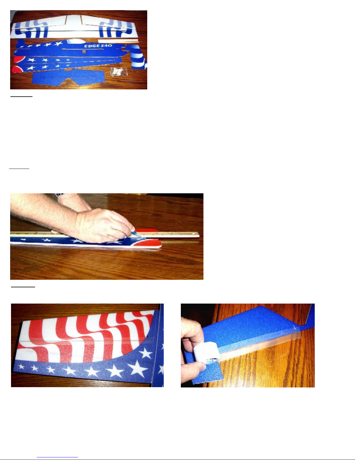
Connect the aileron, rudder and elevator servos to the micro receiver. Using Velcro, install the micro
receiver on the underside of the fuselage. Determine the length from the rudder and elevator control
horns to the servos and using the supplied .060 carbon rod, some heat shrink tubing and 4 pieces of
.032 music wire, make up the elevator and rudder pushrods as shown. Secure the .032 wire to the
.060 carbon rod with heat shrink, then wick some thin CA onto the heat shrink and “kick it” with CA to
strengthen the joint.
At this time, make two standoff pushrod supports from a Popsicle stick or a coffee stirrer, like the
ones at Starbucks and slip one over each .060 pushrod before you put the end on the pushrod. See
the picture at the top of page 5. Wait until you have the pushrods connected before you cut the
supports to the right length and Ca them in place."
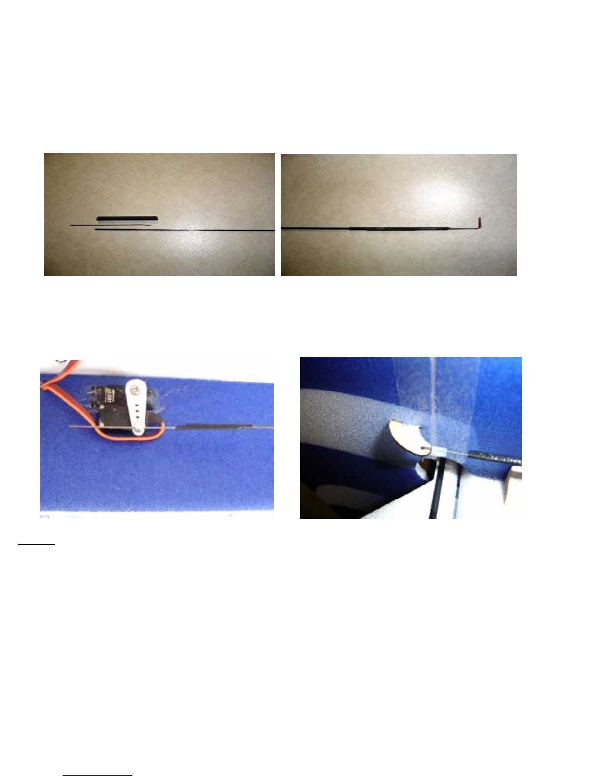
Insert the rudder and elevator servos into the square hole underneath the wing. The servos should
lay on top of each other and face away from each other when installed. Secure them with CA. Attach
the rudder and elevator pushrods to the servos, using either z-bends at the control horns or L-bends
with Dubro micro E-Z links (pictured).
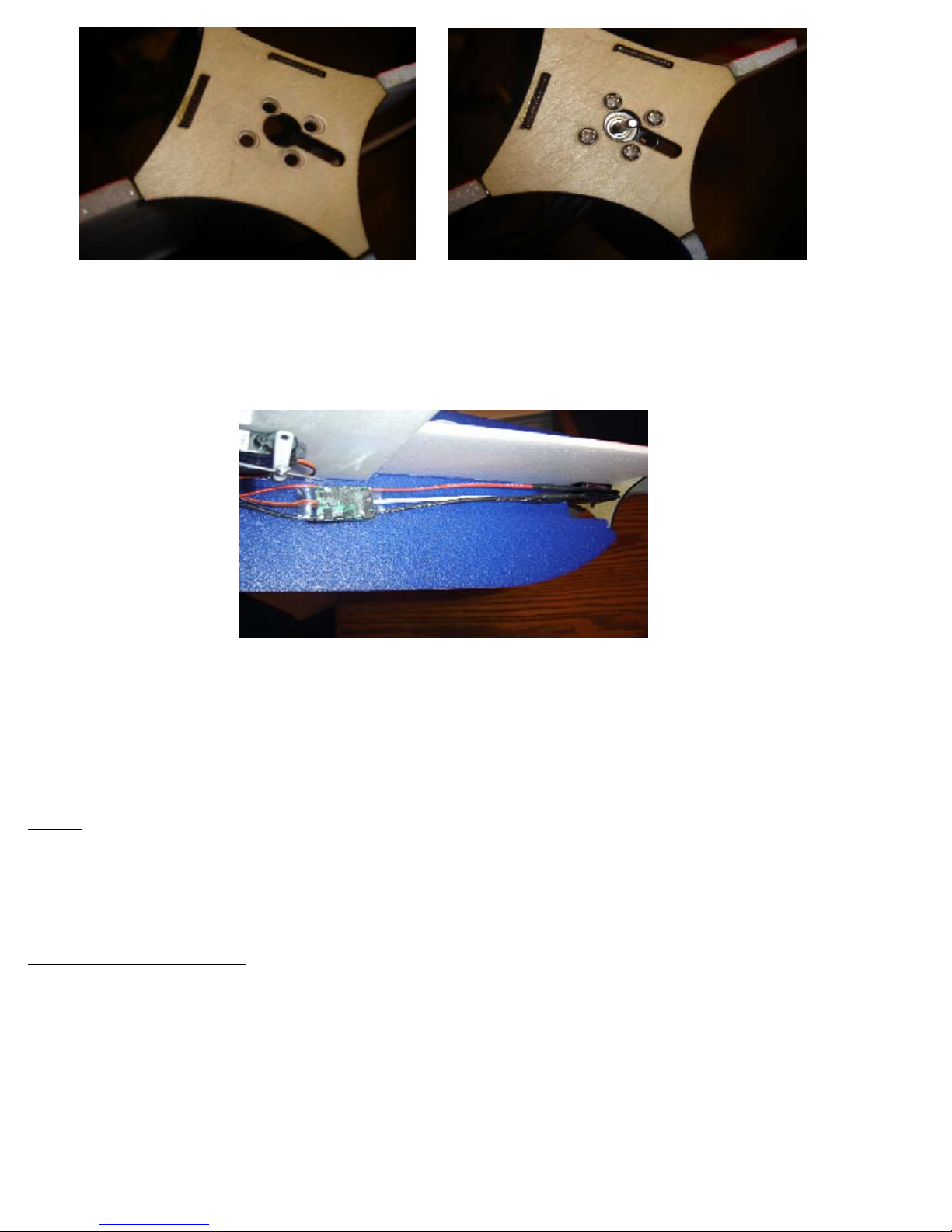
Step 7: Counter sink the four holes on the front of the firewall. This can be done easily with a Dremel
tool with a round ball cutter attachment. Insert the motor shaft underneath the fuselage behind the
firewall (the slotted hole in the firewall allows the motor shaft to be move into position more easily).
Secure the motor to the firewall with the 4 flat head screws included in the motor package.
6

Connect the electronic speed control to the motor and attach it to the fuselage using Velcro. Plug in
the three wires from the electronic speed to the motor. Plug the flat connector from the electronic
speed control into the micro receiver’s throttle position.
(DO NOT install the propeller yet!) Now turn on your radio. Plug the battery into the battery wire from
the electronic speed control. Gently move the throttle stick and check the rotation of the motor. It
should spin counter-clockwise. If it doesn’t, switch around any two of the three wires connecting the
motor to the electronic speed control. Install the propeller using the prop adapter included in the
motor package.
Step 8: Determine the battery location by placing the battery on top of the wing while balancing with
your fingertips on the wing spar. This is the recommended starting point for the CG(Center of
Gravity) location. You may want to move it forward or backward slightly to suit your flying style. Once
the battery position is determined, attach a little longer strip of Velcro on the underside of the
fuselage to secure the battery. This will allow you to adjust the battery fore and aft.
Recommended throws:
Set your high rates at 100% and use as much throw as needed for 3D performance.
High rate exponential: Ailerons- 80% Elevator-65% Rudder-50%. Set your low rates at half of
everything above. Example: Aileron D/R 50% and Expo 40%. Mixes are simple. Start with 6%
opposite aileron with left and right rudder. 3 to 4% up elevator with left and right rudder. Adjust
percentages for knife edge flight.
7

8
First Flight: Wait until a calm day for your maiden flight. Make sure the field is clear of obstacles
and people. After your first flights, you do not need a calm day. You will find that our airplanes fly
well in breezy conditions.
Thank you for purchasing our foam airplane. We will continue to develop the best all-around flying
foam airplanes for your enjoyment.
Darrol Cady
WWW.DarrolCady.com
Table of contents
Popular Toy manuals by other brands

XTM Racing
XTM Racing 146300 Assembly and operating instructions

Tyco
Tyco XFO instruction sheet

Hasbro
Hasbro STAR WARS R2-D2 Operation manual

Eduard
Eduard 36 285 manual

GREAT PLANES
GREAT PLANES ElectriFly Sopwith Pup instruction manual

Horizon Hobby
Horizon Hobby HANGAR 9 Pitts S-2B 50-60cc instruction manual