DASS Tech Soleaf Air DSR-004-OD User manual

Soleaf Air (DASS Wi-Fi)
CM-04A001e
(DSR-004-OD)
Version 1.1
User Manual

2
Table of Contents
1. Safety Precautions .........................................................................................................2
1.1 Basics................................................................................................................................................................2
1.2 Precautions for Use....................................................................................................................................3
2. Product Overview.................................................................................................................4
2.1 Basics................................................................................................................................................................4
2.2 Product Appearance.................................................................................................................................5
2.3 Product Check..............................................................................................................................................5
2.4 Product Composition................................................................................................................................6
2.5 Product
Dimensions...................................................................................................................................8
3. Installation ............................................................................................................................8
3.1
Transportation...............................................................................................................................................8
3.2 Place of Installation....................................................................................................................................9
3.3 Installation Precautions............................................................................................................................9
3.4 Installation Precautions..........................................................................................................................10
3.5 Precautions for Wiring...........................................................................................................................11
3.6 SETUP
Method….………………………………………………………………………………………………………...15
4. Product Specifications…...................................................................................................17
5. Warranty..........................................................................................................................18

3
1. Safety Precautions
1.1 Basics
lFollowing these safety precautions will ensure the safe and proper use of the
product and help prevent accidents and minimize hazards.
lThe various symbols along with their meanings used in the User and Installation
Guide and on the product itself are shown below.
Warning against risks under certain conditions.
Warning regarding risks of electric shock possible under certain conditions.
lSafety Precaution is divided into two categories: 'Warning' and 'Caution'.
The following:
Warning : Failure to follow instructions can result in serious injury or death.
Caution : Failure to follow instructions can lead to a minor injury or product
damage.
lAfter reading the Instructions for Use and Installation, keep it in a place where
the user can see them at any time.
lPlease familiarize yourself with the information in this manual to understand the
functions of Soleaf Air and safety.
4
1.2 Precautions for Use
Warning
Do not drive with the front cover open.
The power switch and PCB are exposed, and can cause electric shock.
Do not operate the switch with wet hands.
It may cause electric shock.
Do not open the front cover except for regular checks, even if the power is not on.
Even if power is lost, the internal PCB in the terminal may be charged, causing an electric
shock.
When performing wiring or routine checks, turn off the power and check that the input
power of the terminal is discharged with measuring equipment such as Multi-Tester (VOM)
after 5 minutes.
The high voltage may be charged to the PCB inside the terminal, causing electric shock.
Do not use the wire when it is damaged.
It may cause electric shock.
Do not place heavy objects on the wire.
Damage to the wire sheath can cause electric shock.
Do not input power even if installation is complete on terminals with damaged parts.
It may cause electric shock.
Caution
Do not install near flammable materials.
Installation on or near flammable materials may cause fire.
In case of terminal failure, disconnect the terminal input power.
Failure to do so may result in a fire caused by a secondary accident.
Do not turn on the power even if the installation is complete on devices with damaged
products.
It can cause electric shock and bring damage to additional parts.
Do not allow foreign substances such as screws, metal substances, water or oil to enter the
terminal.
It may cause fire.
5
2. Product Overview
2.1 Basics
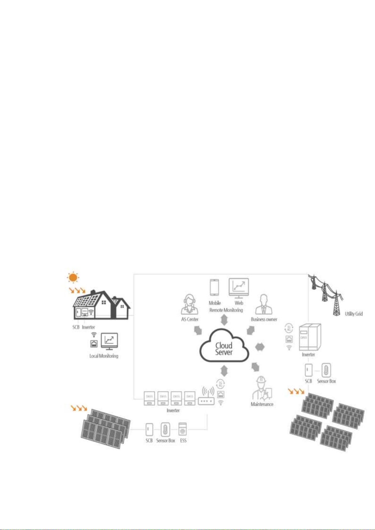
Soleaf Air receives information from solar inverter, sensor box for weather observation, and
system interface and sends information to the server so that power generation corporations can
monitor solar power generation facilities remotely. Please familiarize yourself with this manual
before installing or using the product.
It can be connected to a solar inverter and, when connecting the device, it must be connected
to the communication port specified for that device with the RS485 interface. Device information
collected from the Soleaf Air can be sent to a web server or local server via the RS485 interface to
monitor solar energy integrated generation information in real time or to retrieve historical
information stored on the server.
Plant information and account information required for server account setup and Soleaf Air
setting are generated and managed by the monitoring maintenance specialist. Contact your
monitoring maintenance specialist to learn how to install, connect, and monitor your monitoring
device, and access the server.
Figure 1. Overview of the Soleaf Air Solar Monitoring System

6
2.2 Product Appearance
Figure 2. Soleaf Air Appearance
2.3 Product Check
Remove the device from the box, check the nameplate on the side of the body, and see if the
device format matches the product ordered. Also, make sure that there is no damage made
during transport.
Terminal TYPE
Symbol : DSR
Name : DASS RTU
Symbol : 4
Group Name :
004 Series
Symbol : OD
Group Name :
External/Internal

7
lAccessories
- Contact us if there are any accessories missing from the power cord, operation and
installation manual, fixed screw (CAD blocks), antenna, and USB wires.
- The preparations for operation vary depending on the installation site, so prepare the parts as
necessary. (Example - Multi-Tester for voltage and wiring checkup, power tools for installation
and fixing, etc.)
2.4 Product Composition
lFront view
Figure 3. Front view of product (LNK/STA/PWR status light indicator)

8
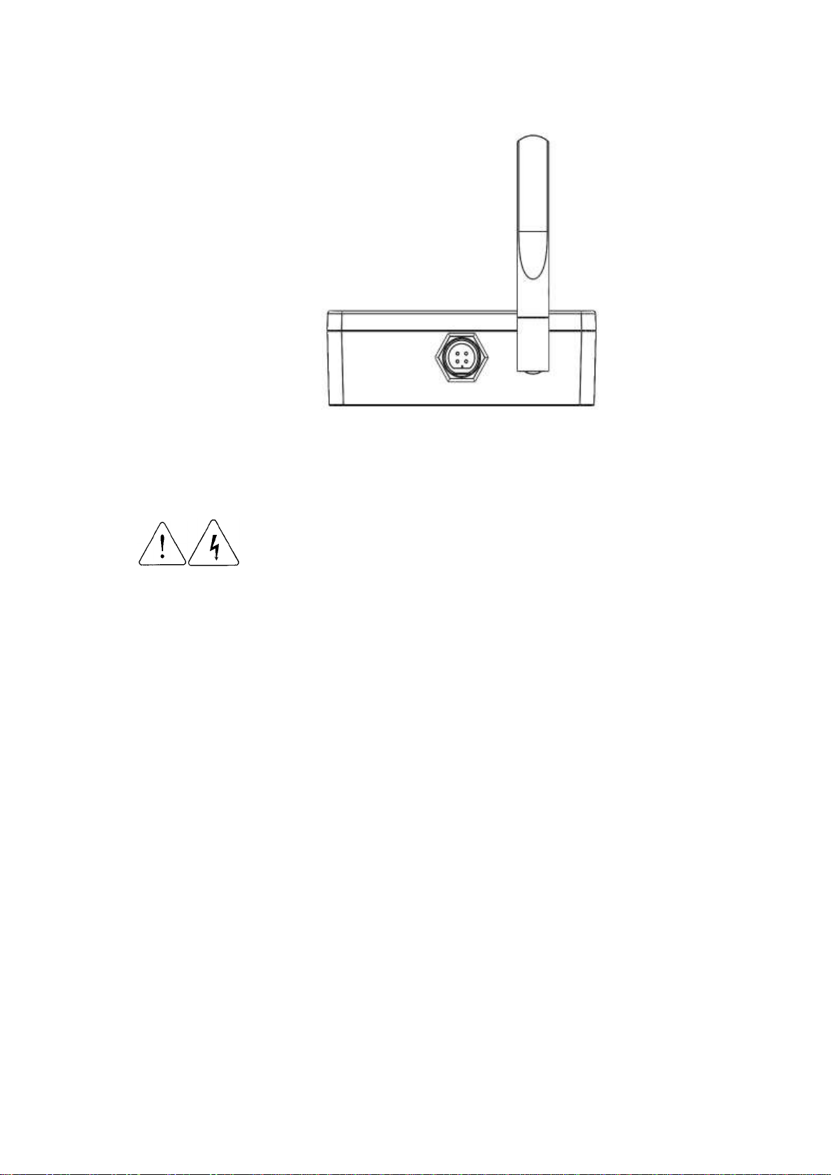
Upper view
Figure 4. Upper view of product (Antenna and Inverter Connections)
Mainboard communication port and connector composition
1② ③ ④ ⑤ ⑥
Number
①
②
③
④
⑤
⑥
Description
Antenna
4-pin
Connector
Emulator
connector
Reset Switch
RS485 and power cord
USB
connector

9
2.5 Product Dimensions
Figure 5. Dimensions : 94mm(w) * 73mm(h) * 31.5mm(d)
3. Installation
3.1 Transportation
Please transport by proper means according to product weight.
Please check external conditions.
Do not pile up beyond the limited level or height.
Do not open the cover while being transported.
Do not drop or cause damage with shock
10
3.2 Installation Location
Install it in a location that meets the following conditions:
To prevent life or performance degradation, install Soleaf Air in a location that does not
receive direct sunlight.
Do not install it in a place with vibration.
As the lifetime of the product is greatly affected by ambient temperature, do not allow the
ambient temperature of the installation site to exceed the allowable temperature (20°C to
50°C).
Avoid hot and humid places (relative humidity is below 90% and there should be no dew
formation).
Avoid locations with oil mist, flammable gas, fiber dust, dust and moisture.
Install at the place where no salt exists.
Install in a location where the Wi-Fi signal is highly sensitive. Poor Wi-Fi signal sensitivity will
prevent smooth communication. (Check sensitivity using Wi-Fi sensitivity measurement
application.)
Avoid places with low signal sensitivity, such as walls or enclosures.
3.3 Installation Precautions
lFollow the instructions in this operation and installation manual.
lThis product may be installed indoors and outdoors.
lBe careful not to install in a wet, dusty, direct ray of sun light or high temperature location.
lWhen installing outdoors, make sure that there is at least one meter of space from the
ground.
lDo not place any heavy items on the product.
lDo not spray or place flammable substances on this product.
lInstallation direction must be set followed by the guidelines in this manual.
lDo not drop or cause damage with shock.

11
3.4 Installation Precautions
Please refer to the diagram below for installation.
Figure 6. Soleaf Air Installation Method
1) Drive a hole in the wall to attach at a vertical 45mm gap of 2 points the CAD block nut to be
tightened with the collar. The enclosed CAD block nut specification is M4*35. (see Figure 2)
2) Insert the nut into the machined hole and attach it firmly using a tool such as a hammer.
3) Attach the bolt to the attached nut.
Here, do not fully attach but remain 3 to 4 mm from the wall (see Figure 1).
4) Attach the product to the bolt and press lightly in vertical downward direction to fix it. (See Figures
2-3)
5) If the product is loosely attached or difficult to attach, retry by adjusting the screw spacing. (See
Figure 1)
12
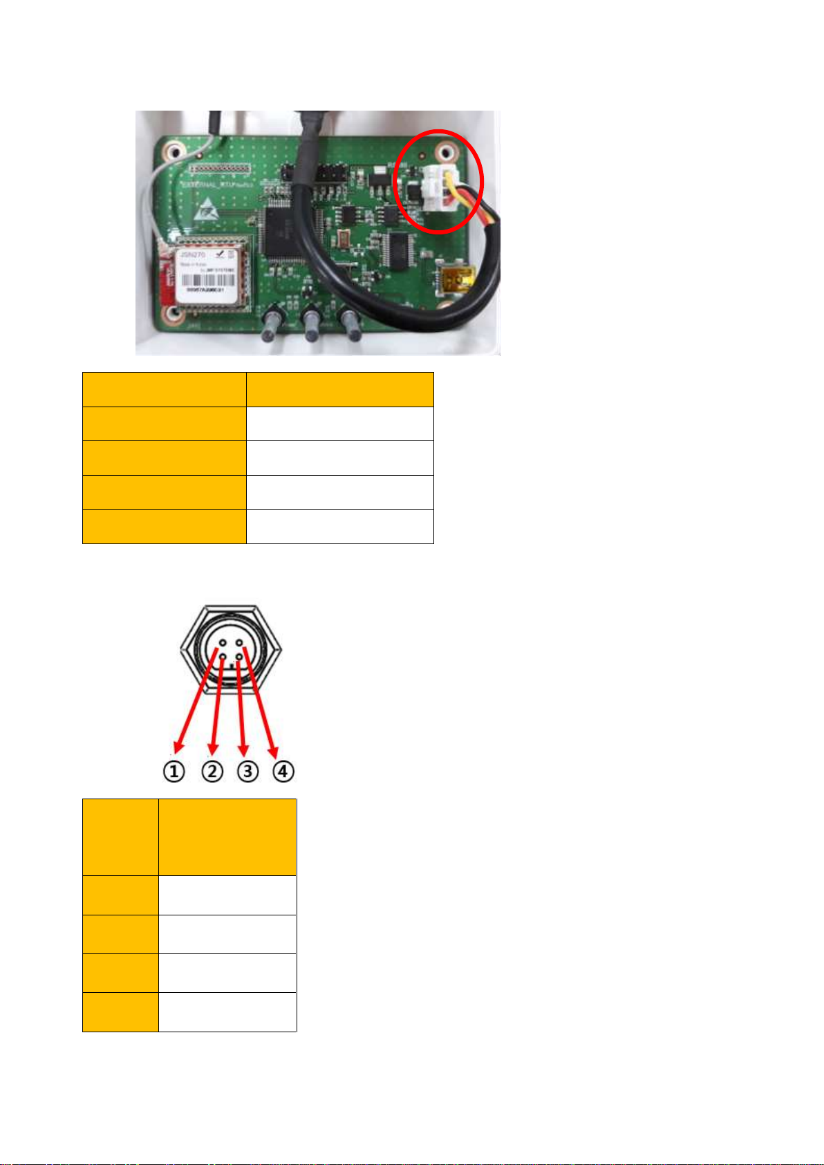
3.5 Precautions for Wiring
Figure 7. Antenna and Power Cord Composition
For safety, be sure to check that power is off when connecting power
lines!
Connect the inverter connector to the top connector of the Soleaf Air.
Pay attention to the separation of power and ground wires when connecting the AC connector.
The Soleaf Air uses a 5V power source inside the inverter for power. If it is not properly connected,
the wires must be carefully routed as this may malfunction or damage the Soleaf Air. Connect the
inverter, system connection board RS485 connector, to fit the hole.
lInstall the Soleaf air before wiring (connector connection).
lTurn on the inverter power to the 'ON' state after the wiring is complete and before closing the
cover.
lWhen the cover is closed and powered on, the Soleaf Air is powered on.
Do not open the cover or disconnect the connector while it is operating.

13
For safety, be sure to check that power is off when connecting power
lines!
lAC Power Line Connections
Connect the power line to the lower input of the cut-off switch by processing the wires or
terminals. Connect one line to one terminal without dividing the polarity of the line. Do not
connect the ground wire.
lSerial Connection Termination Resistance Processing
lWhen connecting the S ㅐleaf Air to multiple units (up to three units), the communication line
must be terminated to ensure smooth serial communication. As communication between devices
may be abnormal if the termination resistance is not handled or handled incorrectly, to enable
termination resistance on the appropriate device referring to the diagram below. Since the serial
communication termination resistance process may vary by inverter models, refer to the
corresponding inverter manual for details on how to set it up. If more than four inverters are
connected to the Soleaf Air, communication will not take place. Check the quantity of inverter
that can be connected.
(Termination Resistance ON) (OFF) (OFF)
Figure 8. Soleaf Air/Inverter RS485 Example of enabling terminating resistance
Control board termination resistance in inverter
14
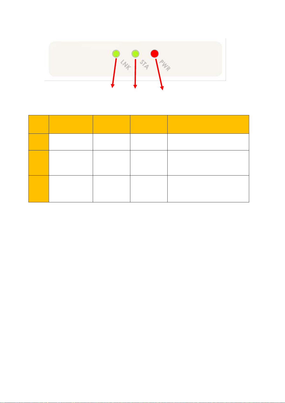
Check operation through status lights when inputting power
①② ③
Figure 9. Soleaf Air Status Light Composition
Num
ber
Description
Normal
Operation
Abnormal
Operation
Examples of Abnormal
Operation
①
Wi-Fi Status
Indicator
ON
Flash
Wi-Fi connection not connected,
Wi-Fi signal is weak
②
Inverter
Connection
Status Indicator
ON
Flash
Inverter disconnected
③
Power Status
Indicator
ON
OFF
If there is no power supply,
PCB is out of order
lThe 'Power Status Indicator' lights up when the Soleaf Air is powered on. The 'PWR Status
Indicator', 'STA Status Indicator', and 'LNK Status Indicator' remain lighted when power is
connected. If the 'PWR Status Indicator', 'STA Status Indicator', and 'LNK Status Indicator' flash or
turn off, check for basic status such as whether there is a connection between the Soleaf Air and
the inverter, etc.
lIf the 'Power Status Indicator' is off, make sure that the inverter that supplies power to the Soleaf
Air is not turned off. If the external switch and power supply are proper functioning, the Soleaf air
internal switch may be switched off. In this case, contact your monitoring maintenance specialist.
lIf the 'STA Status Indicator' flashes, it may not be connected to the inverter. Even if the inverter
stops operating at night, the indicator may flash. Check that the Soleaf Air is properly connected to
the inverter and if there is any problem, contact the inverter maintenance specialist.
lIf the 'LNK Status Indicator' flashes, the Wi-Fi network may be disconnected. Make sure that the Wi-
Fi signal strength and the sharing device you use are not turned off, and that Internet service is
provided normally. If there are no problems with peripheral devices, contact your monitoring
specialist.
15
l4-pin Connector
Line Color
Description
■ Red
5V
■ Black
GND
■ White
Data +
■ Yellow
Data -
Num
ber
Description
1
Data -
2
Data +
3
5V
4
GND

16
3.6 SETUP Method
1. Connect the Soleaf Air to the PC and inverter respectively and run the ezsetup file.
2. Select the PORT associated with your PC and OPEN (only the red light will be displayed if you
enter setup mode later)
3. Click READ to confirm the response.
※Always press READ or WRITE to confirm that the LOG RAW DATA responds with RX

17
4. Enter the information in <General Information>, <Communication>, and then WRITE.
※RTU codes can be entered from 0 to 255
※If using static IP, select address allocation manually and enter IP, NETMASK, GATEWAY, DNS
and WRITE
5. Click on the inverter or system interface at the top -> READ click -> ID, enter model name ->
WRITE
※The system access panel ID must be the same as the corresponding Inverter ID.
6. When all settings are complete, press CLOSE and exit ezsetup.
18
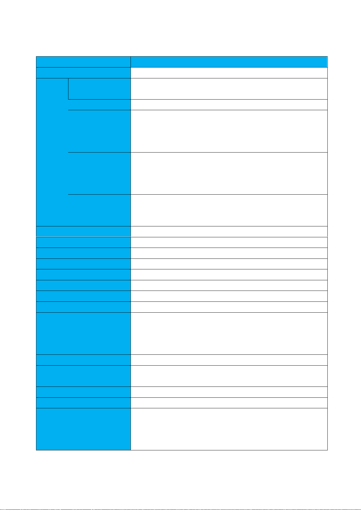
4. Product Specifications
Specification
Standards
Product Name
Soleaf Air (DASS Wi-Fi)
WIFI
Specifica
tion
Operating
Frequency
2.412~2.477GHz
Supported Speed
Max 72Mbps
Output
17dBm@1Mbps, 15dBm@11n MCS0,
13dBm@11n MCS7
Reception
-97dBm@1Mbps, -93dBm@11n MCS0,
-75dBm@11n MCS7
Antenna
Connection
Method
UFL Type
MCU
TI TM4C123GE6PZ
Non-volatile Memory
32KB(MCU built in)
Volatile Memory
128KB(MCU built in), 128KB(I2C EEPROM)
WIFI Connector
For JSN270IF
Debug Port
USB serial(mini USB), 1x3 2.54mm pin header(UART)
NB-IOT Connector
1x13 1.27mm pin header socket(RIGHT)
LED
3(POWER, STATUS, LINK)
LED Status Color
POWER : Red, STATUS, LINK : Green
RS485
Non isolated, Half-duplex
Max. 1Mbps
JTAG Connector
2x7 2.54mm pin header
POWER and Usage
Environment
5V / 1A(input voltage range 4.5V ~5.5V)
PBA Size
50mm x 90mm
Dimensions
93mm x 73mm x 31.5mm
Certification
KC Certified Class A (R-R-Das-DSR-004-OD), Waterproof IP54
- This device is for work-purpose (class A) electromagnetic
compatibility device and is intended for use outside the home
by the seller or the user.

19
5. Warranty
Letter of Warranty
Product
WIFI AIR
Model
CM-04AO01
Date of Purchase
Warranty Period
3 years from the date of purchase
Customer
Name
Address
Contact
Dealer
Name
Address
Contact
• The company manufacturing this product does not take any responsibility for safety
accident or failure due to the customer’s mistake or false use violating
specifications
• The dimension or appearance design of this product can be changed without any notice.
• This warranty is only available in Korea.
• This warranty will not be reissued, please keep it with the manual.
◀ Free A/S ▶
If failure occurred under normal using condition within the warranty period, your product can be tested and
repaired for free.
◀ Charged A/S ▶
For following cases, A/S could be provided at a cost
• The product is out of order due to the customer’s intention or carelessness
• The product is out of order due to failure in connected devices by error of applied power supply
• Any failure due to natural cause
• In case the product was repaired or revised at unofficial service center/man, not designated
• Absence of Dass Tech nameplate
• In case any failure occurs after the user dismantled, repaired or replaced our products
• If consumable parts are replaced due to expiration
• If a product has been modified or repaired by someone other than the designated service personnel
• In case warranty period is expired
(
Co) Dasstech

20
- M E M O -
Table of contents
Popular Data Logger manuals by other brands

Hioki
Hioki 8420-51 Quick start manual

Geosense
Geosense GEOLOGGER G8 PLUS Advanced instruction manual

Logic Beach Incorporated
Logic Beach Incorporated IntelliLogger Using

SalvationData
SalvationData Video Investigation Portable user manual

Extech Instruments
Extech Instruments RHT10 user guide

Nidac
Nidac Presco PACDL Technical manual


