Geosense GEOLOGGER G8 PLUS Setup guide

1
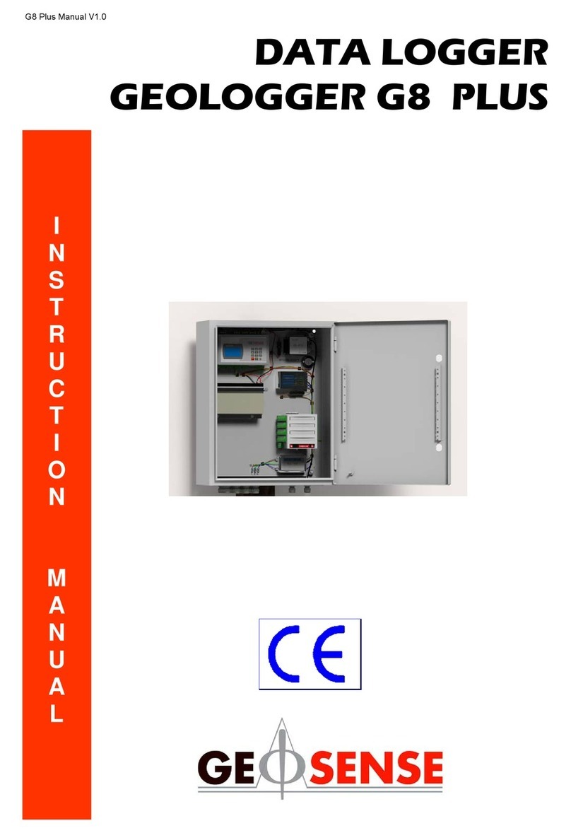
DATA LOGGER
GEOLOGGER G8 PLUS
A
D
V
A
C
E
D
I
N
S
T
R
U
C
T
I
O
N
M
A
N
U
A
L
CONFIGURATION & WIRING OF PERIPHERALS

2
CONTENTS
DESCRIPTION PAGE
Main components 3
G8 Module Connections 4
G8 Module Connections (bottom side) 5
G8 Module connections (top side) 6
Mains powered schematic wiring diagram 7
SmartMux ID setup 8
Rebooting a SmartMux 9
Digital SmartMux overview 10
Analogue SmartMux inputs 11
Wiring options to analogue SmartMux 12
Grounding the VW sensor shield wire to analogue SmartMux 13
Grounding the G8 and/or Remote SmartMux 14
G8 to analogue SmartMux system configurations 15
Typical wiring between G8 & analogue SmartMux (G8 at start of chain) 16
Typical wiring between G8 & analogue SmartMux (G8 in middle of chain) 17
G8 to analogue SmartMux connections (RS232) 18
Router/modem setup 19
G8 as a Web Server 20
G8 as an FTP server 21
G8 configuration 22

3
Enclosure - which houses all the above
components mounted, pre-wired and pre-
programed in a robust IP65 enclosure for
mounting on a suitable location such as a wall or
support frame.
SmartMux (Analogue / Digital): A smart
relay mechanism controlled by the
CPU to switch between multiple sensors so
that they can be monitored by a single
CPU. Allows multi sensors to be fed into the
measurement & control module.
Power Supplies: A power supply provides
regulated power to the logger and sensors.
12 volt DC fed either by 220 volt mains
adaptor and charger with 12 Volt DC battery
back up, 12 Volt DC battery with solar panel.
Communication: Remote or local
connection to the CPU to program or
download data including GSM, GPRS, radio
and cable.
Barometer - for compensation due to
changes in barometric pressure for sensors
used for pressure monitoring. (Not shown).
Main Components
Central processing unit (CPU) – G8
Module to which all the components are
linked.

4
RS485b DIGITAL
DEVICE TO G8
INPUT / OUTPUT
RS485a DIGITAL
DEVICE TO G8
INPUT / OUTPUT
2X OPTIONAL G8
TO DEVICE
POWER OUTPUTS
SD CARD SLOT FOR DATA
BACKUP
LAN PORT FOR NETWORK TO G8
DIRECT CONNECTION OR G8 TO
MODEM LINK
RS232b ANALOGUE
INPUT / OUTPUT
RS232a ANALOGUE
INPUT / OUTPUT
USB PORT FOR
DATA BACKUP
DIGITAL IN 1
LOCAL
DIGITAL
DEVICE TO G8
INPUT
DIGITAL IN 0
LOCAL
DIGITAL
DEVICE TO G8
INPUT
ANALOG IN 0
LOCAL
ANALOGUE
DEVICE TO G8
INPUT
ANALOG IN 1
LOCAL
ANALOGUE
DEVICE TO G8
INPUT
POWER INPUT AND
SWITCH
ON
OFF
FOR RADIO
INTEGRATED
SYSTEMS ONLY
Remember to insert the SD card
with the metal contacts facing UP
2X OPTIONAL
DEVICE TO G8
ALERT INPUTS
G8 Module Connections

5
[2] Not used - always have DOWN
COM BA+12V COM BA+12V
A separate module is
required for radio
outputs
[1] 120Ω Termination Resistor
RS485a (#1) RS485b (#1)
Digital Sensor
Digital Bus
Analogue Mux
Digital Mux
Tx Rx COM
Radio
+5V/
+12V
Siren
Horn
Light
+12V
COM
Power OUT
Modem, Mux
G8 Module Connections (bottom side)

6
G8 Module Connections (top side)
Trigger
Pulse Counter
Analogue Input 0
0-10V | 0-3V | 4-20mA | COM
USB Port for data
backup
SGLC mv/V????
Channel can receive single ended voltage signal

7
Mains Powered G8 Enclosure
Schematic Wiring Diagram
Battery
Fuse
EMC
filter
240V - 12V
Transformer
Fuse
Modem
Radio
Antenna
MAINS IN SENSORS IN
G8 Module
SmartMux

8
MUX ID 30
MUX ID 20
MUX ID 1
MUX ID 10
SmartMux ID Setup
SmartMux IDs are determined by the use of mini dipswitches at the front of each unit. These are usually preconfigured before you receive
them, according to your system design.
[1] Not used - always have DOWN
[2] 120Ω Termination Resistor - only have UP
when at the end of the string
[1] RS232/RS485 Switch - DOWN for RS485
[2] Not for customer use - always have DOWN
The setup is based on zero index binary, with the least
significate bit at the front.
Examples:
1 in binary is 00000001; on the mux it will be 10000000
15 in binary is 00001111; on the mux it will be 11110000
WHY back to front?!

9
A SmartMux will memorise the name of the first G8 it
communicates with and will only communicate with
that G8 from then on. If the G8 ID is changed, the mux
will not communicate with it.
A sign that this is happening is that the data file states
“NO-RX” where there should be data. In addition to
this, the red light on the SmartMux will not flash, only
the green light will come on (the SmartMux will take a
reading but it will not send it to the G8)
Rebooting a SmartMux
Reboot Mode
Rebooting the SmartMux will cause it to lose it’s memory and it will then be
able to communicate with a new G8
1. In the middle block of dipswitches, push all 1-8 up
2. Supply power to the mux. The easiest way to do this is by creating a local
reading of that mux (any channel)
The red and green LED lights on the front of the mux will flash alternately
3. After the lights begin to flash, press ESC repeatedly until the flashing stops
4. Rename your SmartMux by changing the dipswitches back to their original
configuration
5. Take a local reading from the SmartMux to confirm that you get a response

10
Incorporating a Digital SmartMux (DMUX) with Analogue SmartMuxs (GMUX)
NOTE
Digital & analogue SmartMuxs can
be connected together within a
chain
The digital SmartMux MUST BE at
the end of the RS485 line
The digital SmartMux only has one
ID per channel so you can either
connect one digital sensor (or string
of digital sensors) or an analogue
SmartMux into each channel
GMUX
ID0004
G8
Channel 1
Channel 2
Channel 3
Channel 4
Channel 5
Channel 6
Channel 7
Channel 8
…
Channel 16
GMUX
ID0005
GMUX
ID0006
GMUX
ID0007
Channel 1
Channel 2
Channel 3
Channel 4
Channel 5
Channel 6
Channel 7
Channel 8
…
Channel 16
Channel 1
Channel 2
Channel 3
Channel 4
Channel 5
Channel 6
Channel 7
Channel 8
…
Channel 16
Channel 1
Channel 2
Channel 3
Channel 4
Channel 5
Channel 6
Channel 7
Channel 8
…
Channel 16
Channel 1
Channel 4
Channel 3
Channel 2
Channel 1
Channel 2
Channel 3
Channel 4
Channel 5
Channel 6
Channel 7
Channel 8
…
Channel 16
Channel 1
Channel 2
Channel 3
Channel 4
Channel 5
Channel 6
Channel 7
Channel 8
…
Channel 16
Channel 1
Channel 2
Channel 3
Channel 4
Channel 5
Channel 6
Channel 7
Channel 8
…
Channel 16
Channel 1
Channel 2
Channel 3
Channel 4
Channel 5
Channel 6
Channel 7
Channel 8
…
Channel 16
RS-485
RS-485
GMUX ID0001
GMUX ID0002
GMUX ID0003
Each channel can
take one
RS-485 digital
input

11
mV/V Sensors
VW +Temp Sensors
4-20mA Sensors
TOP
BOTTOM
RS232 (For Radio Module)
EXTERNAL POWER SUPPLY
G8 RS485a/b
Analogue Smart Mux inputs
+V In GND

12
Channel 9 Sensor
1234
Channel 10 Sensor
1234
Channel 11 Sensor
1234
Channel 12 Sensor
1234
Channel 5 Sensor
1234
Channel 6 Sensor
1234
Channel 7 Sensor
1234
Channel 8 Sensor
1234
Channel 1 Sensor
1234
Channel 2 Sensor
1234
Channel 3 Sensor
1234
Channel 4 Sensor
1234
R232
TxD RxD GND
+V
Out
Channel 13 Sensor
1234
Channel 14 Sensor
1234
Channel 15 Sensor
1234
Channel 16 Sensor
1234
4-20mA output
Uniaxial Tilt x2
No temperature
PT100
Voltage output
Uniaxial Tilt
No temperature
4-20mA output
Biaxial Tilt
No temperature
Wiring Options to Analogue Smart Mux
PT100
VWSG
Vibrating wire output
With temperature
VW Load Cell
(6 sensors)
VWP
More wiring options

13
12345678
12
12
RS485
RS232
GND GND GND
Typical data from a mains powered system where the shield wires from the sensors have not been connected to the multiplexer
Grounding the VW Sensor Shield Wires to the Analogue Smart Mux
Reduce the effects of electronic interference by grounding the sensor cables to the
GND ports on the right side of the mux
RS232
1 2 3 4
1 2 3 4
1 2 3 4
1 2 3 4

14
Grounding the G8 and/or Remote SmartMux
Remote mux enclosure is
connected to an earth ground
cable or to a bus bar
Mains power has it’s own earth cable
Common ground
connects any mux
to the G8
BATTERY
- +
G8
M2
M3
M1
Twisted pair
provides A & B
signals whilst
cancelling out
noise. Signal
ground is therefore
not required
The return of
the battery
provides the
ground
You can connect the
enclosure the
physical earth
especially in areas
common to lightning
strikes

15
G8 to Analogue Smart Mux System Configurations
G8 within the string, not at
the beginning or end:
RESISTOR OFF
Mux at the end
of the string
RESISTOR ON
G8 at the beginning of the
string: RESISTOR ON
Mux at the end
of the string
RESISTOR ON
Mux at the end
of the string
RESISTOR ON
RESISTOR
OFF
RESISTOR
OFF
RESISTOR
OFF
RESISTOR
OFF
RESISTOR
OFF
1. Mux - G8 - Mux - Mux……(n) Mux
2. G8 - Mux - Mux - Mux……(n) Mux

16
12345678
12
12
COM B A +12V
COM
B
+12V
A
RS485b
Enclosure 1
RS485
Typical Wiring between G8 and Analogue Smart Mux Configuration
G8 at the start of the chain
12345678
12
12
12345678
12
12
RS485
COM
B
A
12V
RS485
COM
B
+12V
A
REMOTE SMARTMUX xxxxx
REMOTE SMARTMUX yyyyy
REMOTE SMARTMUX zzzzz
Enclosure 2
G8

17
COM B A +12V
RS485b
12345678
12
12
RS485
+12V
REMOTE SMARTMUX xxxxx
Typical Wiring between G8 and Analogue Remote Smart Mux Configuration
G8 in the middle of a chain
12345678
12
12
12345678
12
12
RS485
COM
B
A
12V
RS485
COM
B
+12V
A
REMOTE SMARTMUX yyyyy
REMOTE SMARTMUX zzzzz
Enclosure 3
COM
B
A
COM B A +12V
RS485a
Enclosure 2
Enclosure 1

18
G8 to Analogue Smart Mux Connections (RS232)
Useful if the two RS485 ports are already in use
Supplying
Mux String 2
Supplying
Mux String 1
VA+ B-
GND
The RS232 connection on the Mux is not designed for a direct
connection from the G8 to a Mux.
To connect the G8 to a Mux using the RS232 ports on the G8,
you must use an RS232 - RS485 converter to change an
analogue signal into a digital signal. You would then connect
to the Mux using the RS485 connector block
The RS232 connection on the mux is used for radio
connections
RS232 - RS485 Signal Converter
RS485 OUT
RS232 IN
RS232 OUT
RS485 IN
RS232 - USB Type B Cable
G8
String 1
GMUX 1
String 1
GMUX 2
String 1
GMUX 3
String 1
GMUX 4
String 2
GMUX 1
String 2
GMUX 2
String 2
GMUX 3
String 2
GMUX 4
String 3
GMUX 1
String 3
GMUX 2
String 3
GMUX 3
String 3
GMUX 4
Signal
Converter
Example system using a signal converter
analogue
digital

19
Router/Modem Setup
Parts of the standard router
LAN Cable: Connect your
PC to the Modem for initial
setup, and then to connect
the modem to the G8
Antenna: Required for
GSM connection. The
modem will not work
without this, or another
SMA antenna connected
Mains supply: 2 pin
plug provided
The Router
LAN Port: Plug in your
LAN cable here to
connect via G8 or PC
SIM Card Slot: SIM
card is placed chip
side up
Antenna
Connector
Power In

20
Router/Modem Setup
Powering the router
When installed in an enclosure like this, the router can be powered by the G8
itself using the MOD1/2 connectors
When powered AND connected, the router
lights will look like this, with the S1 light
flashing
Other manuals for GEOLOGGER G8 PLUS
1
Table of contents
Other Geosense Data Logger manuals

Geosense
Geosense HLC 6000 Series User manual

Geosense
Geosense Geologger GL101A-V User manual

Geosense
Geosense VW PIEZOMETERS User manual

Geosense
Geosense GEOLOGGER G8 PLUS User manual

Geosense
Geosense Laser Tilt90 User manual

Geosense
Geosense Wi-SOS 100 User manual

Geosense
Geosense Geologger Linx User manual

Geosense
Geosense VWNPC-3000 User manual

Geosense
Geosense Geologger Linx User manual