m-Dimension 12Z8NV User manual

ISO 9001:2000 Certified Company
DC to AC Power Inverters
OWNERS MANUAL for Model:
121718B
12Z8NV
24Z8NV
48Z8NV
Form 121718
OWNERS MANUAL JANUARY 2007
Manufacturer of DimensionsTM Inverters
4467 White Bear Parkway
St. Paul, MN 55110
Phone: 651-653-7000 Fax: 651-653-7600
E-mail: [email protected]
Web: www.dimensions.sensata.com

OWNERS MANUAL
FOR SENSATA TECHNOLOGIES
DIMENSIONS INVERTERS
Model 12Z8NV
Model 24Z8NV
Model 48Z8NV
Table of Contents
Page
1. General . . . . . . . . . . . . . . 2
2. Description . . . . . . . . . . . 2
3. Installation . . . . . . . . . . . 3
4. Start Up/Operation. . . . . . 4
5. Troubleshooting. . . . . . . . 4
6. Installation Figure . . . . . . 5
7. Warranty . . . . . . . . . . . . 6
Page 2
1. GENERAL
1.01 Dimensionsinvertershavebeendesigned
andmanufacturedformanyuserapplicationsand
long life. They utilize patented construction
methods and high technology electronic parts
and circuitry.
1.02
CAUTION:
Inverters produce hazardous
voltages, to avoid risk of harm or fire the unit
must be properly installed. There are no user
serviceablepartsinside,donotremovethecover.
CAUTION:
The inverter should not be installed in
a zero clearance enclosure.
CAUTION:
Damage to the inverter will occur if
correct polarity is not observed when installing
the DC input cables.
CAUTION:
Damagetotheinverter will occur if an
externalACpowersourceisappliedtotheinverter’s
AC output or its hardwire output.
CAUTION:
Theinverter containsacircuit breaker
and a capacitor that may produce a spark. Do not
mountinaconfinedbatteryor gascompartment.
CAUTION:
Working in the vicinity of lead-acid
batteries is dangerous. Batteries generate explo-
sive gases during operation. There is a risk of acid
exposure. There is also a risk of high current
dischargefrom shortingthebatterythatcancause
fire and explosion.
CAUTION:
Besuretheinverter's circuit breakeror
fuse are turned "OFF" during installation.
2. DESCRIPTION
2.01 The inverter converts 12VDC, 24VDC or
48VDC depending on inverter model to a 120VAC,
60HZ,havingapuresinewaveformsignaloutput.
2.02 The inverter has a controlled frequency
at 60 HZ + 0.6Hz.
2.03
The inverter has internal protection
against output short circuit, output overload and
high temperature conditions.
2.04 The inverter is designed to operate
any 120 VAC, 60 HZ, single phase appliance,
equipment or tool within its power ratings.
2.05 The inverter has a ventless cover to
protect the inside electronics from the elements
and is designed to be used on scissor lift applica-
tions.
2.06 The inverter is GFCI protected but does
nothavestandardGFCIoutlets.The120VAC,60Hz
output is supplied by a female receptacle cord
attached to the unit.
2.07 The inverter does not have a "On"/"Off"
switch. The unit must be controlled by a remote
switch, a violet wire is attached to the unit for this
purpose.
Inverter Ratings
Inverter Input Output___
Model (VDC) (ADC) (VAC) (Watts)
12Z8NV 12.6 Up to 80 120 800
24Z8NV 25.2 Up to 40 120 800
48Z8NV 50.4 Up to 20 120 800

resultwhenconnectingthebatterywiringduetoan
initial charging of the internal input capacitor.
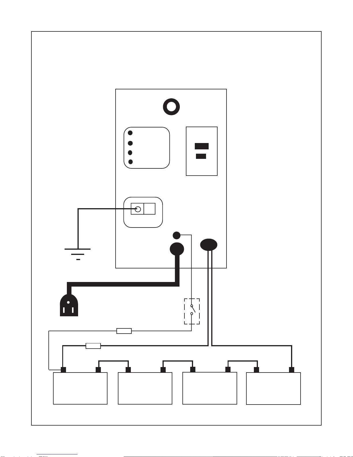
3.05.2 Use stranded copper wire between
the battery and inverter as indicated. A fuse must
be installed between the battery and the inverter.
U.L. requires that the fuse be within 18 inches of
the battery.
DC Input Cable Lengths (maximum)
and Fusing Guide
Distance(feet)
Model 1 to 20 Fuse
12Z8NV 6 Ga 150A
24Z8NV 8 Ga 100A
48Z8NV 8 Ga 100A
3.05.3 NOTE: Using smaller input cable
or longer length will greatly degrade the inverter
peak performance.
IMPORTANT NOTE FOR VEHICLE
INSTALLATION:
Do not use the vehicle chassis
as the negative return in place of a return cable.
Use the same size wire as the positive cable and
run directly to the battery.
3.05.4 Install the cables at the battery,
inverter and then fuse holder. Make sure that
clean,tightconnectionsaremade. Usecarenot
totouchthepositiveandnegativewirestogether.
Thiswillresultinaviolentsparkandcouldresultin
explodingbatteriesandfire.
3.05.5 The battery input terminals are at-
tached to the unit : Red (+) and Black (-) cable,
having 5/16" ring terminals. A spark may result
whenconnectingthebatterywire, due to an initial
charging of the internal input capacitor.
3.05.6
CAUTION:
Damage to the inverter
will occur if correct polarity is not observed. This
damage is
NOT
covered by warranty.
3.06 Remote Switch for Inverter
Operation - Fig. 1
3.06.1 All material used for the remote
switch should be U.L. listed and installed per low
Page 3
3. INSTALLATION
3.01 The following instructions should be
thoroughly read and understood before installa-
tion.
3.02
CAUTION:
Inverters produce hazard-
ous voltages, to avoid risk of harm or fire the unit
must be properly installed.
CAUTION:
Damage to the inverter will occur if
correct polarity is not observed when installing
the DC input cables.
CAUTION:
Damage to the inverter will occur if
an external AC power source is applied to the
inverter’s AC receptacle cord.
CAUTION:
Be sure the inverter's circuit breaker
or fuse (if needed) are turned "OFF" during
installation.
NOTE: All wiring must follow the National
Electric Code, Provincial, or other codes in effect
at the time of installation, regardless of sugges-
tions in this manual. All wires should be copper
conductors.
3.03 Mounting
3.03.1 Locate a suitable, secure flat
mounting surface as close to the battery as
possible without being in the same air tight
compartment. Themaximumrecommendeddis-
tance between the mounting location and the
battery is 20 feet. See DC Input Cable Lengths
chart.
3.03.2 The location should have adequate
ventilation and clearance to maintain room tem-
perature while the unit is operating. At least 1/2
inch of clearance is required on all sides.
3.03.3 Secure the unit with #8 or larger
screws or bolts in the mounting slots on the
flanges of the chassis.
3.04 Chassis Bonding Lug - FIG. 1
3.04.1 Connect a #8 gauge or greater cop-
per wire between the bonding lug on the inverter
and the earth grounding system or the vehicle
chassis.
3.05 Battery Wiring - FIG. 1
3.05.1
CAUTION:
Make sure that hydro-
gen gas does not accumulate near the battery by
keeping the area well ventilated. A spark may

5.02.1 Connect a 100 watt light bulb to the
inverter output.
5.02.2 Make sure the inverter is turned
"On", the output circuit breaker is reset and that
the voltage is at least 12VDC, 24VDC or 48 VDC
(depending on inverter model) at the DC input
terminals. If not, check DC wiring connections
and the line fuse.
5.02.3 Check the connection to the
remote switch, +12VDC, +24VDC or +48VDC
must be present at the violet wire for the unit to
operate. If not, check any in-line fuses in the
+12VDC, +24 or +48 VDC remote switch circuit.
5.02.4 Observe the fault indicating lights
on the front of the inverter.
a) The Low battery light indicates a low
battery condition. Switch the inverter “Off” for 5
seconds, then “On” again. The light coming on
againindicatesafaultinthebatterywiring,battery
capacity and voltage or the fuse.
b) The Overload light indicates an output
wiringshortcircuitoraloadthatistoolargeforthe
power rating of the inverter. Switch the inverter
“Off”, remove the short circuit or excessive load
from the output, then switch the inverter back
“On”. c) TheHightemp. lightindicatestheinverter
has overheated. The unit will automatically turn
back on when it has cooled to 400C (1040F).
5.03 If the above steps are completed and
the inverter still will not operate satisfactorily call
Sensata for a return authorization number.
Page 4
voltage, Class 2, wiring code. The On/Off switch
and in-line fuse to be purchased locally at an
electricalsupplyoutlet.
3.06.2 A 3 Amp rated remote switch must
be connected to the violet wire marked “Remote
On/Off” coming out at front of the inverter.
Connect the violet wire to the load side of the
remoteswitch. Theline side oftheswitchmust be
connected to the DC power source with a 3 Amp
fuse within 18" of the source. The cable clamp
strainreliefshouldbeusedtosecurethefieldwires.
3.06.3 The switch should be mounted at a
convenient location in a listed outlet box with
approved strain relief. The in-line fuse to be
mounted on appropriate fuse holder.
3.06.4
NOTE:
A remote switch, must be
installed to operate the inverter. You may use
several switches or relays in parallel in lieu of one
remote switch.
3.07 120 VAC Output
3.07.1
CAUTION:
Do not connect another
source of AC power directly to the output of the
inverter. This will result in damage to the inverter
that is not covered under warranty!
3.07.2 The 120 VAC output is provided at
the GFCI protected female receptacle cord at-
tached to the inverter.
4. START UP / OPERATION
4.01 To operate the inverter turn the remote
switchto“On”. Makesurethattheoutputbreakeris
reset.
4.02 Turn the switch to “Off” when the inverter
is not in use.
5. TROUBLESHOOTING
5.01 Sensata offers free phone consultation
concerninginstallationortroubleshooting. Callthe
Customer Service Department at:
1-800-553-6418 or 1-651-653-7000
Fax:651-653-7600;
e-mail: [email protected]
5.02 If the inverter fails to operate correctly,
use the following troubleshooting procedure.

Page 5
Fig #1
FRONT VIEW
Output Breaker
Inv. Power
Low battery
Overload
Hightemp.
Dimensions
Chassis
Bonding Lug
Fuse
Fuse
Remote
On/Off
Switch
Black (-)
Red (+)
Battery
Input
Remote
On/Off
A.C.
Output
120VAC, 60Hz
Output
+ -
12VDC
+ -
12VDC
+ -
12VDC
+ -
12VDC
Note 1: Remote switch to be connected to +12VDC, +24VDC or +48VDC depending on inverter model.
Ground
WIRING DIAGRAM FOR MODEL 48Z8NV
GFCI
Four batteries in series

Page 6
Limited Warranty Terms & Conditions
SHIPPING TERMS: F.O.B. St. Paul Minnesota. Freight prepaid and billed, subject to prior credit approval.
MINIMUM ORDER: $50.00 Net Price
LOSS OR DAMAGE: Loss or damage in transit are the responsibility of the carrier. Any claim should be filed with the delivering transport
company. Invoice, Bill of Lading and Delivery receipt with damage noted therein must accompany any claims for freight damage. Claims for
shortage and lost shipments must be made in writing to Sensata Technologies, Power Controls White Bear, St. Paul, MN within 10 days of
date of shipment. Claims not reported within this time frame will not be honored.
PRICES: Prices are subject to change without notice. All orders are subject to acceptance at the factory. We reserve the right to invoice
prices in effect at time of shipment.
TERMS: Net 30 days with approved credit, credit card or C.O.D.
RETURNGOODSPOLICY:
•No returned materials will be accepted without an accompanying Returned Materials Authorization Number (RMA) from the factory.
The RMA number must be clearly printed outside the inverter box.
•Credit will be issued for returned goods to the original purchaser within 60 days of purchase, provided the inverter is returned to
Sensata unused and not mounted. The amount of credit will be issued at Sensata's discretion based on the condition of the product.
•Customer must be in good standing with Sensata Technologies.
•Inverters that are discontinued, high-voltage (over 24vdc), special-order or used are excluded and will not be eligible for credit. Non-
inverter items such as cable assemblies, fuses and fuse holders, will not be eligible for credit.
•Support components supplied by Sensata vendors will be covered under that manufacturer's credit return policy.
•Customer pays return freight.
PLEASE SHIP AUTHORIZED RETURNS TO:
Sensata Technologies / Power Controls White Bear / 4467 White Bear Parkway / St. Paul, MN 55110
Return Freight Prepaid
LIMITED WARRANTY:
Sensata Technologies extends the following warranty to the original purchaser of those goods subject to the qualifications indicated.
Sensata warrants to the original purchaser for use that the goods or any component thereof manufactured by Sensata will be free from
defects in workmanship from the date of purchase for the period listed on the product label, provided such goods are installed, maintained
and used in accordance with Sensata and the original manufacturer's written instructions. Damages caused by the misuse, undue care or
obvious wear through use will not be covered by this warranty.
Components not manufactured by Sensata, but used within the assembly provided by Sensata, are subject to the warranty period as
specified by the individual manufacturer of said component, provided such goods are installed, maintained and used in accordance with
Sensata and the manufacturer's written instructions.
Sensata's sole liability and the Purchaser's sole remedy for a failure of goods under this limited warranty and for any and all claims arising
out of the purchase and use of the goods, shall be limited to the repair or replacement of the goods that do not conform to this warranty.
To obtain repair or replacement service under the limited warranty, the purchaser must contact the factory for a Return Material Authori-
zation (RMA). Once obtained, send the Return Material Authorization Number along with the defective part or goods to: Sensata
Technologies, Power Controls White Bear, 4467 White Bear Parkway, St. Paul, MN 55110, Return Freight Prepaid.
THERE ARE NO EXPRESS WARRANTIES COVERING THESE GOODS OTHER THAN AS SET FORTH ABOVE. THE IMPLIED WARRANTIES OF
MERCHANTABILITY AND FITNESS FOR A PARTICULAR PURPOSE ARE LIMITED IN DURATION TO ONE YEAR FROM DATE OF PURCHASE.
SENSATA TECHNOLOGIES ASSUMES NO LIABILITY IN CONNECTION WITH THE INSTALLATION OR USE OF THE PRODUCT, EXCEPT AS
STATED IN THIS LIMITED WARRANTY. SENSATA TECHNOLOGIES WILL IN NO EVENT BE LIABLE FOR INCIDENTAL OR CONSEQUENTIAL
DAMAGES.
WARNING:
LIMITAIONS ON USE: DIMENSIONS brand products are not intended for use in connection with Life Support Systems and
for Avionic use. Sensata Technologies makes no warranty or representation in connection with their products for such uses.
R
This manual suits for next models
2
Table of contents
Other m-Dimension Inverter manuals