Dass Soleaf DSP-123JB-OD Instruction Manual

DASSTECH Photovoltaic
Grid-Connected Inverter/
Junction Box
DSP-123K6-OD ver1.3
DSP-123JB-OD ver1.1
Operation and Installation Manual

1
Table of Contents
1. Safety precautions .....................................................................................................................2
2. Product overview.........................................................................................................................5
2.1 Basic issues......................................................................................................................5
2.2 Product specifications.....................................................................................................8
3.
Installation.......................................................................................................................................9
3.1 Block diagram……………………......................................................................................9
3.2 Installation location..........................................................................................................9
3.3 Wiring diagram for connecting terminal......................................................................10
3.4 Wiring...............................................................................................................................11
4. Operation....................................................................................................................................14
4.1 Explanation on functions of display window ..............................................................14
4.2 Display mode for basic status ......................................................................................15
4.3 Operating method...........................................................................................................17
5. Functions...................................................................................................................................17
5.1 Explanations on functions.............................................................................................17
6. Explanations on junction box..................................................................................................19
6.1 Basic specifications.......................................................................................................19
6.2 Components block diagram and names......................................................................19
6.3 Precautions in wiring.....................................................................................................20
7. Maintenance...............................................................................................................................22
7.1 Symptoms of breakdown..............................................................................................22
7.2 Repairing breakdowns...................................................................................................22
8. Quality assurance ....................................................................................................................23
8.1 Warranty.........................................................................................................................23
8.2 Warranty.........................................................................................................................24

2
1. Safety precautions
Make sure to adhere to the safety precautions since they are aimed at safe and proper use of the product by
preventing accidents or hazards in advance.
Precautions are classified into ‘Warning’and ‘Caution’with the following meanings:
Warning: Situations with possibility of occurrence of serious injuries or death if
the instructions are violated
Caution: Situations with possibility of occurrence of minor injuries or product
damage if the instructions are violated
Meanings of pictograms use in the product, and User and Installation Manual are as follows:
is a sign to take precaution since there is concern for occurrence of risks under particular
conditions.
is a sign to take precaution since there is concern for occurrence of electrocution under
particular conditions.
After having read the User and Installation Manual, keep it at a location that can be accessed by all the
users at any time.
Make sure to sufficiently familiarize with the contents of User and Installation Manual in order to
sufficiently and safely use all the functions of DSP series inverter.
Warning
Do not operate while the front cover is opened.
It becomes a cause of electrocution due to the exposure of high voltage terminal or charging section.
Do not manipulate switch with wet hand.
It becomes a cause of electrocution.
Do not open the cover while power is turned on or during operation.
It becomes a cause of electrocution.
Even if power has not been turned on, do not open the front cover except in the event
of regular inspection.
It becomes a cause of electrocution since voltage has been charged over prolonged period of time
inside the inverter even if the power has been turned off.
Turn off the power at the time of wiring work or regular inspection, and make sure to
check that the DC voltage in the inverter has been fully discharged with measuring
device such as multi-tester (VOM), etc. after 10 minutes.
It becomes a cause of electrocution.
Do not use if the sheathing on cable has been damaged.
It becomes a cause of electrocution.
Do not use while heavy objects that impart excessive stress is placed on the electric
cable.
It becomes a cause of electrocution due to damages to the sheathing on cable.

3
Caution
Do not install in close vicinity of inflammable substance.
It becomes a cause of fire if installed onto or attached close to combustible material.
Cut off the inverter input (solar cell) and output (AC system) power in the event of
inverter breakdown.
If it is not cut off, fire can breakout due to secondary accident.
Do not touch inverter for several minutes while the power is connected or cut off.
It becomes a cause of burn if it comes in contact with human body since it is very hot.
Do not input power into inverter with damaged product and components even if
installation is completed.
It becomes a cause of electrocution.
Make sure foreign matters including screw, metallic substance, water and oil do not
enter inverter.
It becomes a cause of fire.
Precautions in use
(1) Transportation
Transfer in proper method in accordance with the weight of the product.
Check for any abnormalities in the outer appearance of the product.
Do not pile up in multiple layers in excess of the stipulated regulation.
Do not open the front cover during product transportation
Do not drop or impart strong impact to the inverter since it is a precision device.
(2) Application method
If the automatic operation functions is set at basic value, it operates automatically if the operating
voltage is exceeded and stops automatically if the voltage falls below the operating voltage.
It can be started and stopped with Operation/Stop key on the keypad.
Since the inverter will be reinitiated after prescribed standard by time if the breakdown contents
are reset, manipulate the breakdown reset switch after having assessed the cause.
Do not remodel the internal aspects of the product.
In the case of initializing the parameter, set the parameter necessary prior to operation again. If
the parameter is initialized, the parameter values will be changed to those set at the time of
shipment from factory.
(3) Measures to prevent occurrence of abnormality
If the inverter becomes destroyed and uncontrollable, there are cases in which the mechanical
device is left unattended in hazardous situation. In order to prevent such situation, install additional
safety device such as circuit breaker, etc.
(4) Repair inspection and component replacement
Do not conduct meg-test (measurement of insulation resistance) for the control circuit of inverter.
Refer to Chapter 6 for inspection.
(5) Discard
Discard as ordinary industrial waste.

4
(6) General issues
Although there are portions of explanation with missing front cover or circuit breaker in the
pictorial explanation indicated in this User and Installation Manual for more detailed explanation,
make sure to operate the product in accordance with the User and Installation Manual after
having installed the front cover and circuit breaker, etc. according to the relevant regulations.
Precautions in installation
(7) Installation
Install in accordance with the contents of the User and Installation Manual.
This product can be installed indoor and outdoor.
Install product within 30m from solar cell panel.
Install in location without humidity or dust, and away from direct sunlight and sections that
generate high heat.
At the time of indoor installation, make sure to secure space of more than 20cm above, left and
right of the inverter.
At the time of outdoor installation, make sure to secure space of more than 1m from the ground.
Installation work must be performed by specialist or technician.
Do not place heavy objects on top of the product.
Do not spray on or keep this product near inflammable substances.
Please comply with the standards indicated in the User Manual for the installation direction.
Do not drop or impart strong impact onto the inverter since it is a precision device.
Execute class 3 (200V class) grounding for inverter.
Do not use other household appliances in close vicinity of this product. Abnormality or noise can
be made in the household appliances.
Make sure to use the rack provided for exclusive use of the product and take precautions against
sharp parts in the rack.
Prior to installing the inverter, install solar cell power (DC) circuit breaker and install the inverter
while the solar cell power is turned OFF. After the installation, turn the solar cell power ON for
operation. If the inverter is installed while the solar cell power (DC) is ON, there is a concern that
inverter may be damaged or operate erroneously.
(8) Wiring
Erroneous terminal contact can become a cause of inverter breakage.
At the time of connecting the DC connector, pay attention to the (+/-) electrodes. Refer to the
installation method in Chapter 3.
At the time of connecting AC connector, pay attention to the distinction between power and
grounding cables. Refer to the installation method in Chapter 3.
Wiring and inspection must be performed by specialist or technician.
After having installed the main body of the inverter, execute wiring works (connect connectors).
(9) Adjustment at the time of trial run
Check various set values prior to operation.
5
2. Product overview
2.1 Basic issues
2.1.1 Contents you need to be aware prior to the use
If inverter is used erroneously, it may not operate normally or its lifespan may be shortened. In the
worst case, inverter can be broken or impart fatal injuries to human body. As such, sufficiently
understand the contents of this User and Installation Manual before using this product.
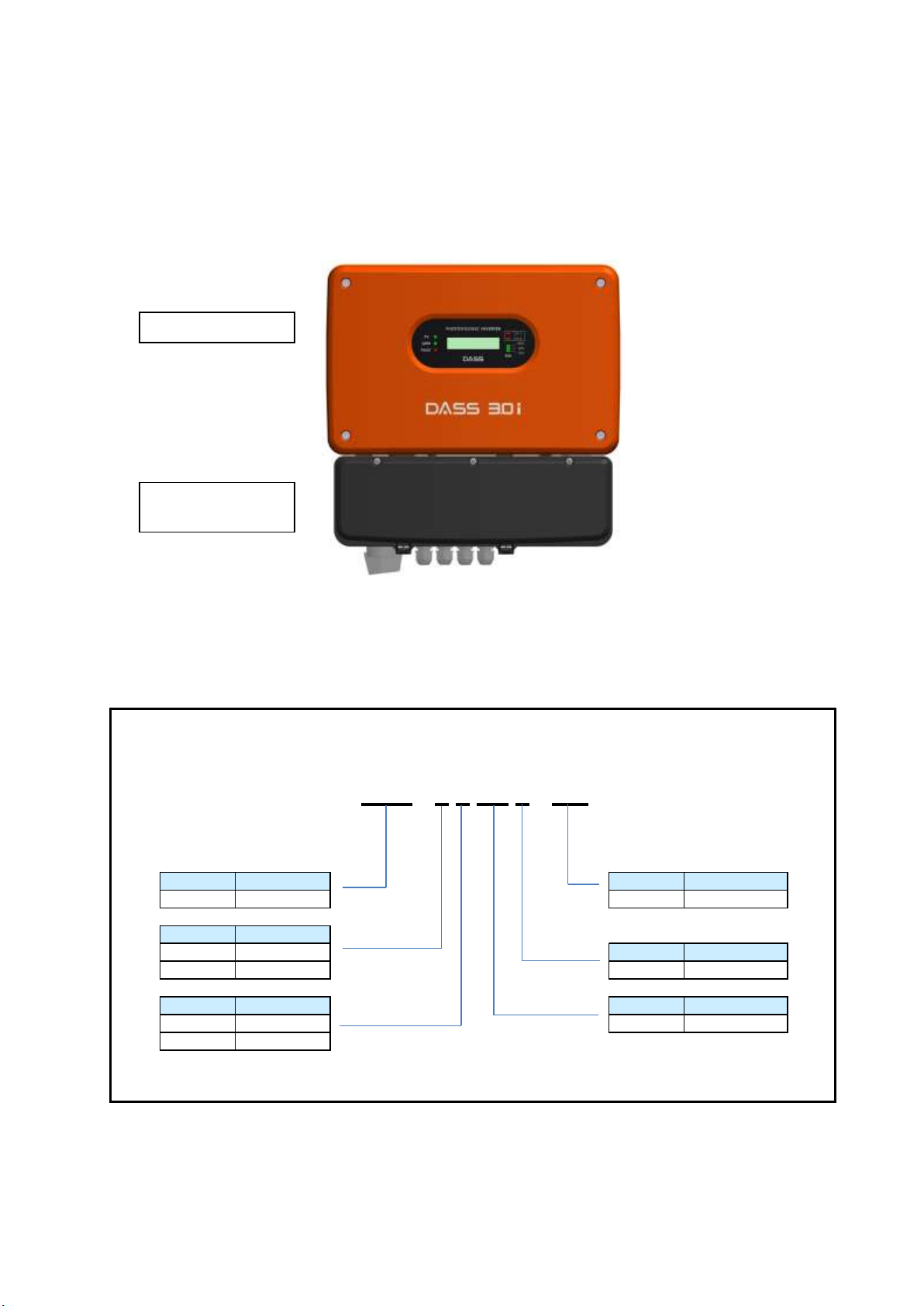
2.1.2 External appearance of the product
2.1.3 Check the product
After having taken the inverter out of the packaging box, inspect the nameplate on the lateral side of
the main body to check the format and rated output of the inverter is the same as those of the product
you ordered. In addition, check for any breakage during delivery.
(1) Inverter types
(2) Components –Please contact our company if there are any components missing including User
and Installation Manual, output (AC) connector, installation rack and components for
fixation at the time of installation, etc., and if there is any breakage in the product.
Code
Name
Type
DSP
DASS Tech.
OD
Outdoor type
Phase
1
Single phase
Type
2
Three phase
6
Series No.
AC voltage
AC voltage
2
220V
3K
3kW
3
380V
DSP
-
1
2
3K
6
-
OD
Code
Code
Code
Code
Code
Inverter section
Junction box
section
6
2.1.4 Preparation of device and components necessary for operation
Since there are some differences in the items to be prepared for operation, prepare components
according to the need (example: multi-tester for checking voltage and wiring, and motorized tools for
installation rack installation, etc.)
2.1.5 Installation
Accurately install the inverter in a location without direct sunlight with considerations for the location
and direction of the installation as well as the surrounding spaces in order to prevent degradation of
the lifespan or performances of the inverter.
2.1.6 Wiring
Connect the solar cell power (DC) and system power (AC) by using terminal block and connector. If
not connected accurately, inverter and surrounding devices can suffer breakage. As such, wire with
caution.
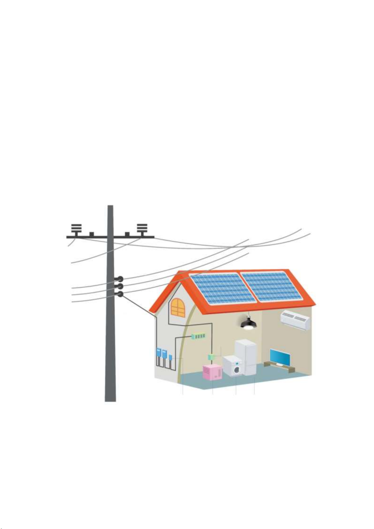
2.1.7 Photovoltaic system composition
Proper contact is needed for the inverter under proper setting of the peripheral devices. Erroneous
system composition and contact can make normal operation impossible or result in substantial
degradation of lifespan. In the worst case, inverter can be damaged due to fire. As such, use the
inverter properly in accordance with the instructions of this Manual and precautions.
High Voltage
distribution line
Commercial System
Low Voltage
distribution line
Lead-in line
Solar cell arrey
Watt-hour
meter
Outdoor
switch
PCS
(Inverter)
Grid
Protection
device
Load
Load
Load
Distribution
panel

7
2.1.8 Product features
(1) High efficiency power conversion
It achieves highly efficient power conversion in PWM format by using IGBT semiconductor device
with high efficiency of more than 96% of the rated output.
(2) Digital control
System control is more convenient through the use of high-performance digital controller that
allows confirmation through LCD keypad. Moreover, operation, input and output status, and
abnormality of inverter are monitored and indicated, and inverter will be stopped in the event of
occurrence of abnormality. It also gets operated and stopped automatically by detecting the
voltage of solar cell module.
(3) Transformerless inverter
DSP-123K6-OD inverter is a transformerless type solar cell inverter appropriate for dispersion
type power system designed to be appropriate for industrial, building and household uses.
(4) Dispersion power system and economic value
Since solar power generation uses power generation format that can be installed at anywhere with
sunlight, it is a format that can achieve economic use due to its ability to establish dispersed
power in the units of building or residence and solar power generation plant.
(5) Maximum Power Point Tracking (MPPT) control
Since occurrence of direct current that is not uniform in accordance with the temperature, humidity,
climate, environment and insolation given the output characteristics of solar cells, inverter controls
the solar cell modules to maintain the maximum power point through MPPT control.
(6) Ease of parallel operation
If the capacity of solar cell module increases, it is possible to easily connect additional inverter in
parallel to increase the capacity without the need of separate additional equipment.
(7) Convenience of installation and operation
It is designed to allow easy and safe connection between solar cell and system power by using
dedicated connector. It is also designed to indicate the status of inverter through the frontal LCD
keypad in real time. In addition, installation is more convenient than the separate connection-board
installation method since it is in integrated junction box format.
(8) High reliability and low noise
Factors that induce defectiveness were reduced by optimizing the inverter components and, in
particular, high reliability and low noise were realized by removing inverter-cooling fan with
mechanical lifespan.
(9) Electromagnetic conformity (EMC)
It was manufactured to be appropriate for household electromagnetic conformity (EMC) by
optimizing the inverter power circuit design (KSC IEC 61000-6-1, KSC IEC 61000-6-3, KSC IEC
61000-6-4).

8
2.2 Product specifications
Model name
DSP - 123K6-OD
Input
Range of operating
voltage (25℃)
100V ~ 500V
Operating MPPT
voltage range (25℃)
200V ~ 400V
Rated voltage (25℃)
360V
Operation initiation
voltage (25℃)
150V
Maximum input
current (25℃)
18A
Output
Rated output capacity
3.5 kW
Rated voltage
System voltage (AC 220/230V +10%/-12%)
Frequency modulation
rate
System frequency (50/60Hz +0.5Hz/-0.7Hz)
Constant
Single phase and 2 lines
Power factor
0.95 abnormality
Current distortion
power (current THD)
Less than 5% of total
Less than 3% of each difference
Control format
PWM format
Prevention of single
operation
Within 0.5 seconds
Efficiency
96% abnormality
Structure
Cooling method
Natural air cooling
Protection structure
IP 65
Device noise
Less than 50 dB
External dimension
358*376*150 mm
Total weight
9kg
External interface
RS485
Monitoring terminal unit (Option)
DSP-WR5/DSP-ZR5/CM-04A001 (wired/wireless, RS485)
Protection
functions
Inverter
Excessive input voltage, output short circuit, overload, inverter
overheating protection, and prevention of DC output discharge
System
Single operation protection, system over-voltage and under-
voltage protection, and system over-frequency and under-
frequency protection
Application
environment
Ambient temperature
-20℃~ 50℃
Preservation
temperature
-20℃~ 65℃
Ambient humidity
Relative humidity (RH) of less than 90% (absence of dew
formation)
Vibration at elevation
Less than 5.9m/sec²(=0.6g) at under 1,000m
Ambient environment
There must be no corrosive gas, inflammable gas, oil mist and
dust, etc.
※Specifications of this product can change without prior notice for reasons such as improvement of quality. Please
inquire at the time of product purchase.
9
3. Installation
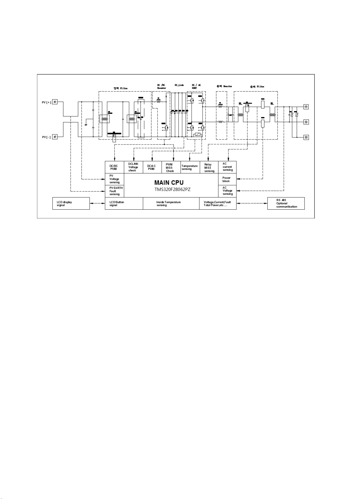
3.1 Block diagram
1) DSP-123K6-OD
※Sections marked with broken line indicate the inner aspect of the inverter.
3.2 Installation location
Please install at a location that satisfied the following conditions.
1) Please install at a location without direct sunlight.
2) Do not install at a location with vibration.
3) Since the inverter lifespan is greatly affected by the surrounding temperature, make sure that the
temperature in the area of installation does not exceed the allowed temperature range (-20 ~ 50℃).
4) Avoid location with high temperature and humidity (less than relative humidity of 90% and absence of
dew formation).
5) Since inverter generates high level of heat, make sure to install it on surface with non-flammable
material.
6) Install the inverter by securing sufficient space around it to allow harmonious dispersion of heat.
7) Avoid location with oil mist, inflammable gas, fibrous dust, dust and moisture, etc.
8) Install it erect by firmly securing with bolts.
9) Install at a location without salinity. (In particular, if it is installed in seacoast, corrosion of the product
can occur. As such, avoid the product coming in contact with salinity in the methods such as use of
separate casing or indoor installation, etc.)
10
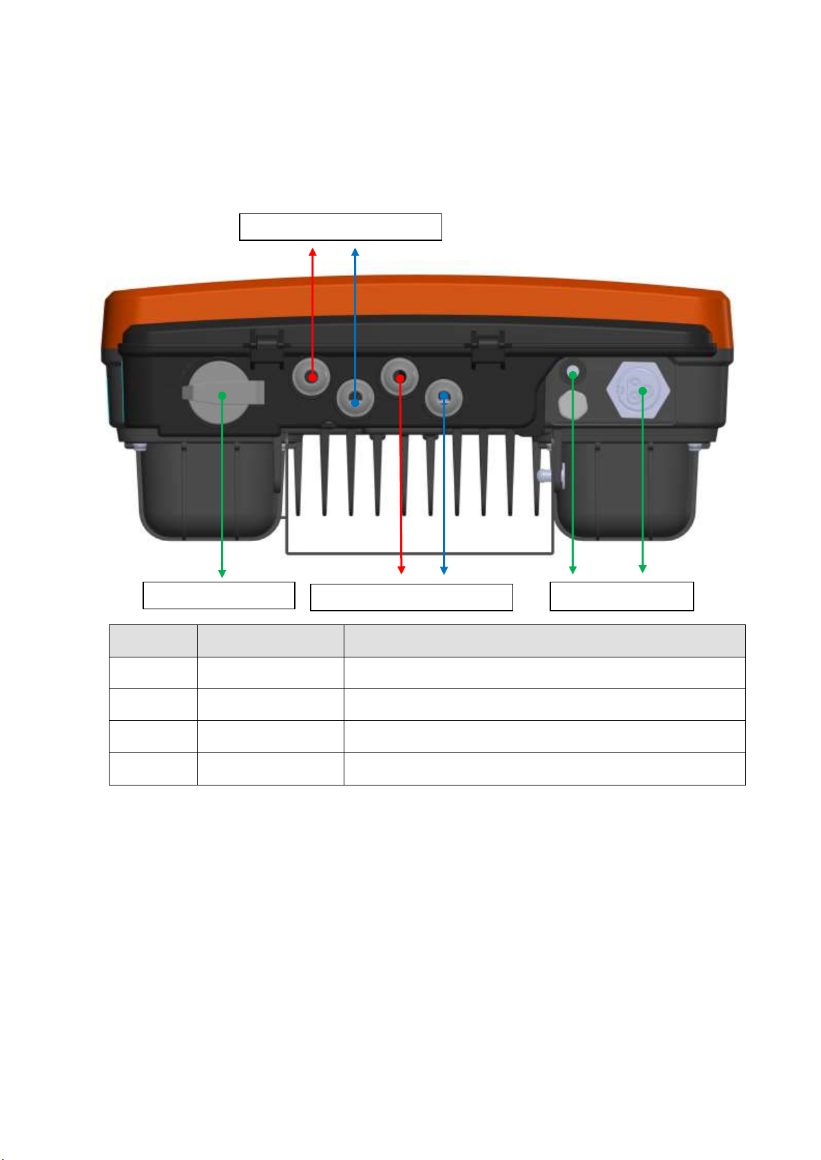
3.3 Wiring diagram for connecting terminal
Section for connection with the connector is situated at the bottom of the inverter.
Read the terminal-wiring diagram carefully before connecting the connector.
1) Explanations on the main circuit connecting terminal section
Terminal
signs
Terminal names
Explanations
DC [+]
PV input power (+)
Connect with the (+) terminal of the output power of solar cell
DC [-]
PV input power (-)
Connect with (-) terminal of output power of solar cell
RS485
Communication
terminal
Connect with the signal line of monitoring system
AC
System power
connection terminal
Output from the inverter is connected to the KEPCO system
and grounding line.
Note) Refer to 6. Explanations on connection board for more details
CH1 DC(+) CH1 DC(-)
RS485 AC
CH2 DC(+) CH2 DC(-)
DC Switch

11
2) Explanations on RS485C communication terminal and connector
Communication output terminal (inside the inverter):
RS485
Communication
BUS(+)
BUS(-)
Red
Black
①
②
Communication connector terminal (outside the inverter):
R485 communication terminal is designed as above.
Communication connector is an optional item. Please inquire with our company if you need
communication connection.
3) Setting of communication protocol
This product supports 2 different communication protocol modes, namely, Dass Tech protocol and
integrated new renewable energy convergence support monitoring system (REMS).
The basic value is set at integrated new renewable energy convergence support monitoring system
(REMS) at the time of shipping from the factory. ID is set at ‘1’as the basic value.
There is a need to change the communication protocol setting at the time of using Dass Tech protocol.
After having accessed Setting menu - Selection Set –REMS Monitor menu, change the set value to
Disable and save with Enter key. Then, cut off the input power to and discharge inverter prior to
reconnecting the power to convert to Dass Tech protocol.
3.4 Wiring
3.4.1 Main circuit wiring
1) Precautions at the time of wiring the main circuit
For input power, connect the CH1/CH2(+)terminal of solar cell panel to the internal
PV1(+)/PV2(+) terminal inside the junction box and CH1/CH2(-)terminal of solar cell panel to
the PV1(-)/PV2(-)terminal inside the junction box before inputting power.
Take precaution against loss due to fire arising from erroneous wiring of the junction box.
Do not disassemble connector during operation.
In the event of emergency power OFF during operation, turn OFF the DC switch of junction box.

12
In the event of altering wiring due to occurrence of incongruity, make sure that the LCD on the
keypad of the main body is turned off prior to conducting rewiring work. Since the internal capacitor
of inverter is charged at high voltage immediately after the power has been turned off. As such, take
precaution against danger of electrocution.
For prevention of electrocution, make sure to execute Class 3 grounding for the inverter and keep
the grounding resistance to less than 100Ω.
For grounding of inverter, connect to the dedicated grounding terminal. Do not use casing or bracket
screw as grounding terminal.
Use dedicated grounding cable. Use the grounding point as near to the inverter as possible. Use
grounding cable with the following thickness by maintaining the length as short as possible.
Capacity
Ground cable thickness (mm²)
1.5 ~ 3.5 kW
4.0
5 kW
6.0
Check the maximum input voltage of inverter and output voltage of solar cell array. If the output
voltage of solar cell array exceeds the maximum input voltage of inverter, it could result in severe
damage of the inverter.
Set the output voltage by considering the temperature coefficient at the time of wiring of solar cell
module. If the output voltage of solar cell array is set without such consideration, excessive or
substandard input voltage of inverter can occur depending on the atmospheric temperature.

13
2) AC Connector installation
3.4.2 Communication circuit wiring
1) Precautions at the time of communication circuit wiring
Use communication connector at the time of control circuit terminal wiring. Refer to 3.3 Terminal
wiring diagram.

14
4. Operation
4.1 Explanations on the display window functions
4.1.1 Exterior of display window
4.1.2 Display window functions and LED indications
Status LED
Explanations
PV
Indicates the status of solar cell string (Green light: Normal solar cell string)
GRID
Indicates the status of the system (Green light: Normal system)
RUN
Indicates the status of inverter operation (Green light: Normal inverter power generation)
FAULT
Indicates inverter breakdown (Red light: Lights up if inverter breakdown occurs)
CH-1,CH-2
Indicates breakdown for each channel at the time of disconnection of junction box FUSE
(Red light: Disconnection of junction box FUSE)
LCD display
window for power
generated
Explanations
100% LED
Lights up at the time of 61 ~ 100 [%] power generation
60% LED
Lights up at the time of 31 ~ 60 [%] power generation
30% LED
Lights up at the time of initial operation and 1 ~ 30 [%] power generation
15
4.2 Display mode for basic status (2-line and 16-character LCD)
Once the power to inverter is turned ON, information on the LCD display window is automatically
converted at every 10-second intervals.
4.2.1 Solar cell input
Input display Input voltage Input current
PV: solar cell DC voltage DC current
Status of inverter operation Unit
4.2.2 System power input
Input display System power frequency System power current
Line: System 60.0 Hz Output current
Status of inverter operation Output voltage
4.2.3 Check total power generated
Input display Total power generated
Total: Total power generated kWh
Status of inverter operation Unit
4.2.4 Check power generated on the day
Input display Total power generated
TODAY: Power generated on the day kWh
Status of inverter operation Unit
→PV 412V 9.0 A
▶▶▶▶▶▶▶▶▶▶ 3.5 kW
→Line 60Hz 16.0A
▶▶▶▶▶▶▶▶▶▶ 220V
→Total 500 kWh
▶▶▶▶▶▶▶▶▶▶ 3.5 kW
→TODAY 10 kWh
▶▶▶▶▶▶▶▶▶▶ 3.5 kW

16
4.2.5 Check power generated on the previous day
Input display Total power generated
DAY-1: Power generated on previous day kWh
Status of inverter operation Unit
4.2.6 Check current power generation
Input display Power generated at the moment
RUN: Status of operation kW
Status of inverter operation Unit
4.2.7 Error status
- Indicated for 5 minutes at the time of error occurrence
Input display Name of error
Error code: S-OV
Explanations on error
→DAY-1 10 kWh
▶▶▶▶▶▶▶▶▶▶ 3.5kW
→RUN 3.5kW
▶▶▶▶▶▶▶▶▶▶ 97.2%
[E012] Sol_OV
Solar Over Voltage

17
4.3 Operating method
4.3.1 Issues to be checked prior to operation
Check the status of wiring and installation of inverter.
In particular, check whether the input polarity of solar cell is accurately connected and whether the
system line connection is made accurately.
Supply DC solar cell power to inverter. When DC power is supplied, the inverter will automatically
check abnormality in AC power before commencing operation automatically after having undergone
300 seconds of operation countdown.
(If needed, apply power by turning ON the DC switch after having checked DC voltage by turning off
the DC switch of junction box.)
4.3.2 Automatic operation
At the time of shipment from factory, the initial setting is in automatic operation mode.
If the solar cell module voltage increases above the set value due to sunlight, the inverter will be
initiated automatically.
At the time of sunset, the solar cell module voltage will be dropped. If it falls below the set voltage, the
inverter will stop operating automatically. The system power is always monitored and the operation will
be stopped automatically in the event of abnormality.
5. Functions
5.1 Explanations on functions
5.1.1 System monitoring
Presence of normal and abnormal system voltage is determined by the difference in the voltage with the
normal voltage (Fault high vtg., Fault low vtg.). If this value is larger or smaller than the designated
value, the inverter will be stopped. If the frequency of the system voltage (Line frequency) is outside the
range of Fault high freq. and Fault low freq. values, it does not operate and stops the inverter.
In order to initiate power generation in normal system status, wait until operation countdown (Line tran.
time) is completed before operating with the system. The frequency of system voltage used can be set
in accordance with the system frequency.
5.1.2 MPPT control and total power generated
Since the output of the solar cell module changes in accordance with the ambient temperature, humidity
and sunlight, Maximum Power Point Tracking (MPPT) algorithm needs to be executed harmoniously.
Format applied to this product has almost no pulsation of current. Inverter will be stopped if the inverter
cannot be operated anymore due to the solar cell reaching the stop voltage (PV stop voltage).
Since the total power generated (Total power) is remembered by being accumulated, it is possible to
check the total power generated.

18
5.1.3 Initialization and measures to be taken at the time of abnormality
In the event of occurrence of abnormality in which the inverter is stopped, relevant message will be
displayed. Once the cause of the abnormality is removed, the system will recommence operation after
the standby time. If the same symptom occurs or reoperation does not occur, please contact our
company. A total of 100 faults will be stored in the order of the faults being scanned scan from No. 0 to
99 with the most recent fault being numbered with 0.
It is possible to discern the variables or the past abnormal status by using the UP and DOWN button on
the keypad inside the inverter.
Parameter values can be changed by using the internal keypad in the event of stoppage of inverter.
Initialization includes Parameter initialization and Fault initialization. Parameter initialization sets all
parameters or optional functions at the value set at the time of the shipment from factory, while Fault
initialization put the system in ready status by removing all the records of faults generated in the past.
Erroneous operation of inverter can occur if the internal keypad is manipulated arbitrarily. Please
contact our company in such event.
5.1.4 Breakdown (Fault)
1) Breakdown (Fault)
Protection against Input over voltage
If the voltage of solar cell is above the stipulated voltage, the system will be stopped to protect the
inverter.
Protection against output overcurrent
If output overcurrent occurs in the inverter under the abnormal conditions of load state, the system will
be stopped to protect the inverter.
Protection against output overload
If there is abnormal output over prescribed period of time in excess of the rated output of the inverter,
the system will be stopped to protect the inverter.
Protection against overheating of inverter
If the internal temperature of the inverter exceeds 105℃, overheating is prevented by stopping the
operation of the system. Once the internal temperature of the inverter returns to normal level, it will be
reset and re-operated normally.
Protection against earth fault
System will be stopped if leakage current occurs due to earth fault.
Protection against system fault (Over/Under frequency fault, Over/Under voltage fault)
System will be stopped in the event of abnormality in the system power (protection of the system and
voltage, low system voltage, over-frequency and under-frequency of the system)
PWM control fault (Over current 2)
System will be stopped in the event of occurrence of abnormality in the internal PWM control of the
inverter.
19
6. Explanations on junction box (DSP-123JB-OD)
6.1 Basic issues
6.1.1 Issues to be aware prior to the use
①Please use the product after having sufficiently familiarized with the contents of this User Manual.
②Make sure to install away from direct sunlight and in a cool location with good ventilation. Fuse may
become short-circuited due to heat if the internal temperature increases because of direct sunlight.
③Do not open the junction box cover unless by skilled technician. Even if the lamp for confirmation of
power doesn’t light up at the time of inverter breakdown, there could be high current flowing in the
junction box. In addition, even of the fuse is short-circuited, electricity is continuously being supplied by
the solar cells. As such, arbitrary removal of fuse can induce electric shock, burn, fire and death. Make
sure to request inspection to specialist solar cell technician.
④Never remove the internal fuse while the inverter is in operation. Since high current flows through the
inverter generating power, you can get burnt or fire can generate along with risk of death in serious
cases due to generation of powerful sparks if fuse is removed forcibly.
⑤Install the junction box in a location that allows the user to inspection it conveniently. Power lamp doesn’t
light up for the photovoltaic inverter in the event of short-circuiting of junction box fuse. Under normal
state, CH1 and CH2 lamps of the inverter section do not operate. (If CH1 and CH2 LED of the inverter
section flickers, inspect the fuse of connection board.)
⑥Do not use impact wrench or motorized tools at the time of connecting cable and tightening of the
external cover of the junction box. Take precaution against breakage of fixation bolt for the terminal
block and external cover of internal PCB at the time of tightening them.
※Repair for breakage arising from negligence in installation will be charged.
⑦If power has not been applied to inverter, check the status of ON and OFF of the DC switch first.
⑧This product is a junction box for exclusive use in DSP-123K6-OD and cannot be used for separation
type or other type of products.
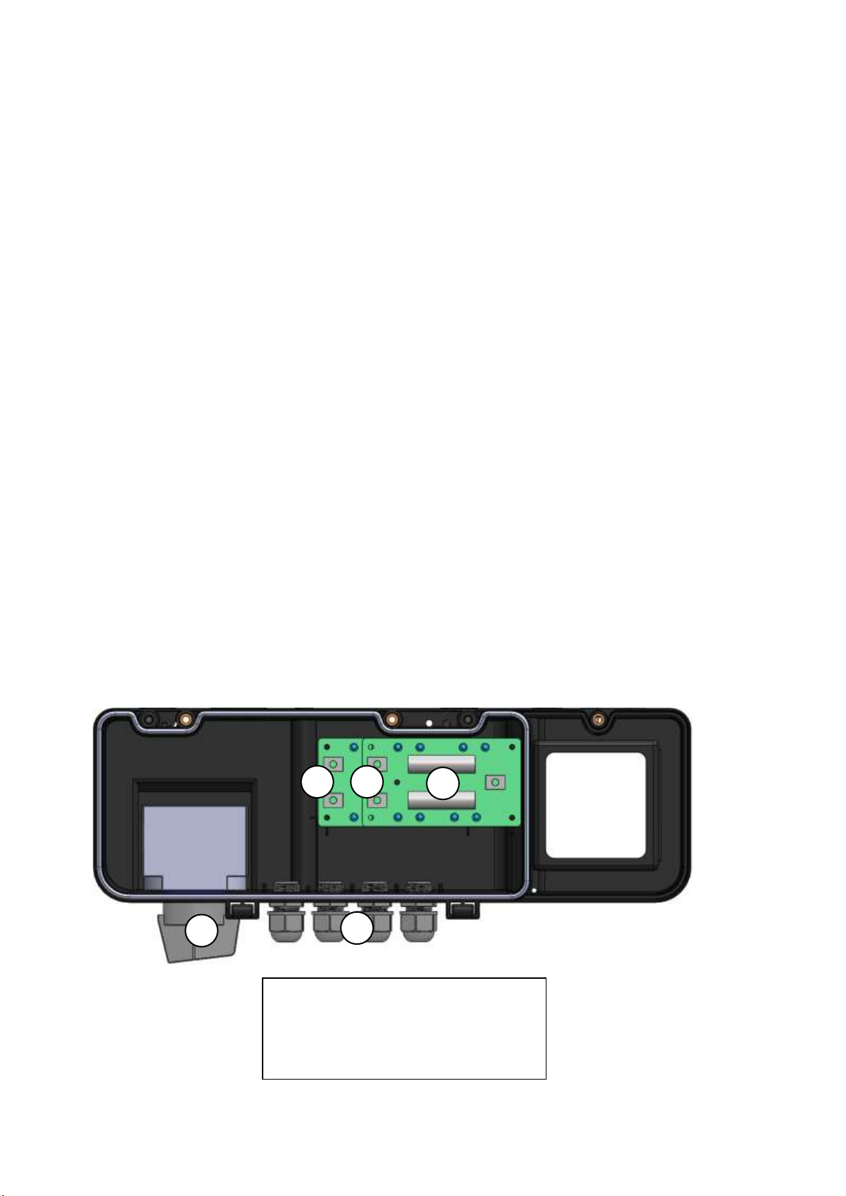
6.2 Components block diagram and names
①DC switch: 600Vdc 25A
②DC FUSE: 1000VDC 20A
③DC (-) input terminal: 30A
④DC (+) input terminal: 30A
⑤DC input (CH 1+,CH1-,CH2+,CH2-)
1
1
3
1
5
1
2
1
1
4
1
This manual suits for next models
1
Table of contents
Other Dass Inverter manuals


