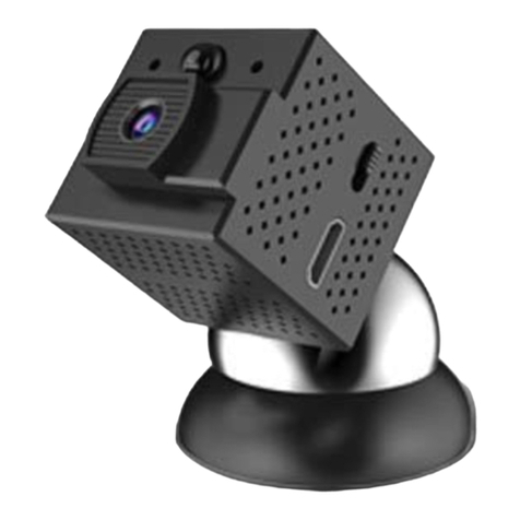
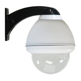
DASYS High Speed Dome User manual

-1-
User sManual
Thankyou forusingour high speeddome. This state-of-the-artspeeddomewill fulfillyour widerangeprofessional
securitysurveillance need.
Features:
l220presets,4 sequences with upto30presets each, 4patternwithmin.180 seconds each, 4autoscan, 8 regions.
lAutoruning, runs theassignedfunctionautomaticallyafter aperiodof idling.
lUpto 8 privacymasks.
lWithdome,preset,pattern, autoscanand region titles, thetitlescanbeset to not display,display or displayfor a
period oftime.
lPowerful OSDmenu, all thefunctions canbesetviaOSD menu.
lWithRS485, Manchester, Bi-phaseor Coaxitroncontrol interface, support Factory,VCL, PELCO-P,PELCO-D,
PELCO-C, PHILIPS,VICON, KALATEL,AMERICANDYNAMICS,MOLYNX, PANASONICetc.protocols.
lBuilt in DSPcamera, with autofocus,auto BLC, autolight control, autowhitebalanceetc. functions.
lColor/monoauto, manual or switchatasettime. (for day/night models).
lWith4000Vvideo, data,powerlightningproof and surgeproof.
lHi-accuracymotor driveswith 0.5 degreepresetaccuracy, min. 0.5degreemovingwithout anyvibration.
l360degree continuous pan,90 degree tiltwith autoflip.
lIP66standardizedfor outdoor speeddome.
WELCOME

-2-User sManual
This equipmenthas beentestedand found tocomply withthelimitsfor aClass Adigitaldevice, pursuant to part 15
of FCC rules and EuropeanUnion 89/336/EEC directiveand its latest amendedversion.Theselimits aredesignedto
providereasonableprotection againstharmfulinterference whentheequipmentis operatedinacommercial
environment.Thisequipment generates, uses, and canradiateradio frequencyenergy and, if not installedandused
in accordancewith theinstructionmanual,may causeharmful interferencetoradiocommunications. Operationof
this equipment inaresidential area is likelytocauseharmful interferencein thatcasetheuser willberequiredto
correcttheinterferenceat his own expense.Modificationsnot expressly approvedbythemanufacturer couldvoid
theuser sauthoritytooperatetheequipment under CE and FCC rules.
Precautions:
1.Onlyqualifiedand experiencedperson cancarryonthisinstallation.
2.Alwaysconformtonationalandlocalsafetycodesduring installation.
3.Usereliabletools only, poor quality tools maycausedanger. e.g.ladder.
4. Doinstallthespeeddometoappropriateenvironment (Refertothechartbelow). Thisproductconforms toIP66
standardas specifiedin “Housing Protection Classification (IP code)”.
5.Checkthespace and toughness of thesitebeforeinstalling. It shouldbeabletobear 4 times theweight of thedome
anditsaccessories.
6.Keepall theoriginaldomepackagematerialsin caseof futurerepackingand transportation.
Warnings:
1. DO NOT install this speeddomeinhazardous places wherecombustibleor explosivematerials arestoredorused.
2. DONOT install indoor domein outdoor environment.
3. This speeddomerunson24V AC. DO NOT connect higheror lowervoltageto it.
4. DO NOT turnpower onbeforecompleting installation.
5. DO NOT disassembleanypartof theitems.
6.Usesoft towelto cleanthedown cover whennecessary. DONOT usecaustic detergent.
7.ToprotectCCD, avoid facingthecamerato direct stronglight. e.g thesun.
ModelIndoorOutdoor
MaximumTemp Range -10 oC~+50oC-40 oC~+60oC
Humidity<90%<90%
AirPressure86~106KPa86~106KPa
Power SupplyAC24V/1.25A,50/60HzAC24V/2.5A,50/60Hz
DECLARATION

-3-
User sManual
INSTALLATIONPREPARATION
ToolsLists:
You mayneedfollowing tools for theinstallation:
Screws andnuts, Philipsscrewdriver, Small slotted
screwdriver,Wirecutter, Ladder,Drill, Saw.
Cables:
VideoCoaxialCable
The videocoaxial cableshouldbe:
1) 75Ohmimpedance.
2) Solid copper wire.
3)95% braidedcoppershield.
Checkthemax transmissiondistancereferringto the
chartbelow.
InternationalGaugeTransmissionDistance(Max.)
RG59/U750ft(229m)
RG6/U1,000ft(305m)
RG16/U1,500ft(457m)
RS485 Cable
0.56mm (24AWG) twistedpair smaxi-
mum transmissiondistancesareasfollows.
Baud RateTransmissionDistance(Max.)
2400bps5,906ft (1800m)
4800bps3,937ft (1200m)
9600bps2,625ft (800m)
DIP switchesand jumperssettings
Referto appendix Ito setthefollowings:
Protocol and Baud rate
Domeaddress
Videocabletype
RS485 terminationresistor
Wiring Diagramforvideo & RS485and
Power
NOTE: UseRS485 distributor ifyouneedtotransmit
further. TolearnmoreaboutRS485, referto appendix
III.
AC 24V
RJ45
RS485-
TX+
TX-
V_gnd
Video
RS485+
1234
DIPSwitch
Video:video signals
V_gnd: videoground signals
TX-/TX+:RS422communication patternandsend
siganls
RS485-/RS485+: receivesignals
AC 24v:ACpower supply

-4-User sManual
INSTALLATION TYPEGUIDE
INSTALLATONTYPE GUIDE
INSTALLATIONTYPE GUIDE
3.PoleMount
2.Corner Mount
4. PendantMount5. ParapetMount
BracketMount
1.Wall Mount
NOTE: Installation siteshouldbeabletowithstand
at least4 timestheweightofthedome.
TypeWeight(kg/lb)
SurfaceDome2.20kg(4.85lb)
IndoorCeilingDome2.43kg(5.35lb)
Indoor Dome
(excludingbracket) 2.93kg(6.45lb)
Outdoor Dome
(excludingbracket) 3.78kg(8.33lb)
PendantBracket1.53kg(3.37lb)
Wall Bracket1.25kg(2.75lb)
CornerBracket1.90kg(4.19lb)
PoleBracket1.20kg(2.64lb)
ParapetBacket6.50kg(14.33lb)
High speeddomeis categorizedinto thefollowing
types:
1) In-ceiling Mount
2)SurfaceMount
3)BracketMount
Thereare5bracketoptionsfor bracket mount:
1)Wall Mount
2)CornerMount
3)PoleMount
4)Pendant Mount
5)Parapet Mount
In-ceilingMount SurfaceMount
NOTE:Bracketmountdomeis classfied intoindoorandoutdoor type. Comparing toindoortype,outdoortypeis
featuredwith extrasun-shield housingandtemperaturesensor, aswell asconforming toIP66 standard.
WARNING: DO NOTinstall indoor domeinoutdoor environment.

-5-
User sManual
In-Ceiling Mount
1Draw acircleonceiling
Determinetheinstallationposition and drawa
circleontheceilingaccording totheaccessory
paperpattern.Thepaper pattern sdiameteris
225mm.
Installationrequirements:
1. Thethicknessoftheceilingshouldbelessthan
42mm
2.Theceilingshould beableto bear 4 times the
weight ofthespeeddome.
3. Upperspaceshould beatleast20cmhigh.
Upper housing
Pan/tiltmodule
Black liner
Downcover
罩
机芯
下罩
Upperhousing
Pan/tilt module
Downcover
NOTE: therearetwo kindsof pan/tiltmodules available
as theleft pictureillustrated. Theuser should beaware
of thedifferencesof two pan/tilt modulesduring the
installation.

-6-User sManual
4Connectcables
Insertcablesintocorrespondingsockets onconnec-
tionboard.Aftercompletingcableconnection, turn
onthepower.TheredLED willlight up. Turnoff
thepowerafter checking. If theredLEDis not lit
up,checkthecableconnection.
NOTE:
lTherearesignsforeachport.Connect cablesas
picture showedin page3.PleaseMAKESURE
powerisoff beforedoingconnection.
lTwo videotransmissioninterfacesareavailableon
thedome.Pleaseconnect videocablewithcorre-
spondinginterfaceasyour requirement.
3Preparecables
Pass theconnection cables (Power/RS485/Video)
throughthewater-proofconnectorandthetop of
housing, and thensecurelytightentheconnector.
Waterproof
Connector
-
1
AC24V 2
RJ45
LED
3
RS485-
TX+
TX-
V_gnd
Video
RS485+
1234
DIPSwitch
Thedomecanbesetfor eithercoaxialor twisted-
paircommunicationthroughDIPswitchasshown
inthefollowing illustration.
1234
CoaxialOFFOFFONON
Twisted-pairONONOFFOFF
Pin positions
connectionmethod
settings
2Cutcircleoff
Useasawor propertoolto cut offthecircle.
NOTE: MAKE SURE thediameter of thecircleis
225+2mmbeforecuttingthecircleoff.
2252±

-7-
User sManual
7Set domeID,baud rateand protocol
SetdomeID, baudrateand protocolviaDIP switches
(pleasereferto APPENDIX I).
6Install housing
Pushhousing intoceilingandlettheclips stretchout
Finally,screwthethreeclips totighten thehousing
NOTE: Useevenstrengthtoadjust thethree clips,
otherwiseitmaydistorttheshapeofthehousing.
SW1
SW2
5Adjust clips
Adjust theheightofthethree mounting clips.Swing
thethree mounting clips to cling themto thehousing.
Ceiling Thickness
MountingClip

-8-User sManual
8InstallPan/Tiltmodule and blackliner
Takedown thekeyringfrom connectionbridge
in thehousingandbutton holeonthebase
boardwiththekeyring.
Loosentwo screwsandmatchthemwithtwo
guidanceholesonthebaseboard.Thenpush dome
moduleupwardand turnit anticlockwiseto theend.
Fastenscrews.
Plug RJ45connectorintothesocket onthepower
boardof thedomemodule.Pushtheblacklinerinto
thetwolockingtabs.
NOTE: When thedomemoduleisinstalled,pleaseturn
on thepowertomakesurethedomemodule isin
goodcondition.
3
2
1
1
2
3
3
SW2
SW1
2
3
1

-9-
User sManual
9Installdowncover
Fixthesafetychainon housing.Thesafetychain
prevents thedown coverdropping down. Matchthe
clasps and mounting holes,andthenturnthedown
coverframeanticlockwise.
NOTE:
lLet thesafetychaininsidethearcgrooveofthe
down cover,otherwiseitmayscratchthelens.
lIfyou finditdifficultto fitin thedowncover,try
to readjustthethreeclips.
SafetyChain
MountingHole
Clasp

-10-User sManual
Surface Mount
1 Detachdown housing
Turndown housing anticlockwiseandpull downthe
down housing.
2
1
Down
Housing
Surface
MountBase
Down
Housing
Surface
MountBase
Slot
Slot
Surtace
MountBase
Down
Housing
Installationrequirements:
1. Theceilingshouldbehardand solid.
2.Theceilingshould beableto bear4 timestheweight
ofthespeeddome.
Pan/tiltmodule
Black liner
Down cover
Upper housing
机芯
下罩
罩
Upper housing
Pan/tilt module
Down cover
NOTE: therearetwo kindsof pan/tiltmodules available
as theleft pictureillustrated. Theuser should beaware
of thedifferencesof two pan/tilt modulesduring the
installation.

-11-
User sManual
4Connect thecables
Insertcablesintocorrespondingsockets onconnec-
tionboard.Aftercompletingcableconnection, turn
onthepower.TheredLED willlight up. Turnoff
thepowerafter checking. If theredLEDis not lit
up,checkthecableconnection.
Thedomecanbeset for eithercoaxial or twisted-
paircommunicationthroughDIPswitchasshown
inthefollowing illustration.
NOTE:
lThere aresigns foreachport.cablesaspicture
showedin page3. PleaseMAKE SURE poweris off
beforedoingconnection.
lTwo videotransmissioninterfacesareavailableon
thdome.Pleaseconnectvideocablewith correspond-
inginterfaceas your requirement.
3Install thesurface mountbase
PassthePower/RS485/Videocablesthroughthecen
tralholeofsurfacemount baseandfixthemonthe
ceiling.
NOTE:Wires canbealsopassedthroughtheside
hole of surface mount base.
1
AC 24V 2
RJ45
LED
3
RS485-
TX+
TX-
V_gnd
Video
RS485+
1234
DIPSwitch
1234
CoaxialOFFOFFONON
Twisted-pairONONOFFOFF
Pin positions
connectionmethod
settings
2 Mark screws positions
Usingthesurfacemount baseas atemplatetomark
thefastenerpositionson theceiling, and thendrill 3
holes.
Side hole

-12-User sManual
6InstallPan/Tiltmodule and blackliner
Takedownthekeyringfrom connectionbridge
in thehousingandbutton holeonthebase
boardwiththekeyring.
Loosentwoscrewsandmatchthemwith two
guidanceholesonthebaseboard.Thenpushdome
moduleupward and turnit anticlockwisetotheend.
Fastenscrews.
Plug RJ45 connectorintothesocketonthepower
boardof thedomemodule. Pushtheblacklinerinto
thetwolockingtabs.
NOTE: When thedomemoduleisinstalled, please
powerontomakesurethedomemoduleisingood
condition.
1
2
3
3
5 Set domeID,baud rate andprotocol
Set domeID, baud rateandprotocol viaDIP switches
(refertoAPPENDIXI)..
SW1
SW2
SW2
SW1

-13-
User sManual
1
3
2
7Installdown housing
Matchthetabs ofdowncoverintotheslotsand turn
anti-clockwisesoas tofix thedownhousing.
NOTE: Check if it is tightly installed.

-14-User sManual
WallMount
Installationrequirements:
Thewall mountingsurface mustbefirmenoughtobear
4 timestheweight ofthespeeddome.
Upper housing
Pan/tiltmodule
Blackliner
Down cover
Upper housing
Pan/tilt module
Down cover
1Mark screwspositions
Takethebracket baseasthetemplate tomarkthe
screws positions on thewall, and thendrill theholes
toinsert expansion screws.
84
140
NOTE: therearetwo kindsof pan/tiltmodules available
as theleft pictureillustrated. Theuser should beaware
of thedifferencesof two pan/tilt modulesduring the
installation.

-15-
User sManual
4Connectcables
Insertcablesintocorrespondingsocketson con-
nection board.Aftercompletingcableconnection,
turnonthepower. TheredLEDwilllightup. Turn
offthepowerafterchecking. IftheredLEDis not
litup, checkthecableconnection.
NOTE:
lTherearesignsforeachport. Connect cablesas
pictureshowedinpage3.PleaseMAKESURE
powerisoff beforedoingconnection.
lTwo videotransmission interfacesareavailableon
th dome.Pleaseconnectvideocable withcorre-
spondinginterfaceasyour requirement.
3Installhousing
Windtheaccessorywaterproof tapearound thecon-
necting part ofthehousing, and thenpass thecables
through thehousing,finallyscrew thehousing clock-
wiseintothebracketandtightentheM4screw.
NOTE: Apply silicon tothegap between thebracket
andthewall in theeventofoutdoor dome.
M4
Tape
1
AC24V 2
RJ45
LED
3
RS485-
TX+
TX-
V_gnd
Video
RS485+
1234
DIPSwitch
Thedomecanbesetfor eithercoaxialor twisted-
paircommunicationthroughDIPswitchasshown
inthefollowing illustration.
1234
CoaxialOFFOFFONON
Twisted-pairONONOFFOFF
Pin positions
connectionmethod
settings
2Install bracket
PassthePower/RS485/Videocablesthroughthe
cavityof thebracket, andtheninstall bracketon
thewall.
NOTE: Pass thecablesthrough thewall or aside
thebracket.
M8

-16-User sManual
1
2
3
1
2
3
3
6InstallPan/Tiltmodule and blackliner
Takedown thekeyringfrom connectionbridge
in thehousingandbutton holeonthebase
boardwiththekeyring.
Loosentwoscrewsandmatch themwithtwo
guidanceholesonthebaseboard.Thenpushdome
moduleupward and turnit anticlockwisetotheend.
Fastenscrews
PlugRJ45 connectorintothesocket on thepower
boardof thedomemodule. Pushtheblacklinerinto
thetwolockingtabs.
NOTE: Whenthedomemoduleisinstalled, please
powerontomakesurethedomemoduleisingood
condition.
SW2
SW1
5Set domeID,baud rateand protocol
Set domeID, baud rateand protocol viaDIP switches
(pleaserefertoAPPENDIXI ).
SW1
SW2

-17-
User sManual
7 Install down cover
Loosenthetwoscrews M4onthedown coverring.
ApplylubricanttotheO-ring to makethedowncover
easiertoslipin. Push upwardthedowncoverinto
thehousing and thenfastendown coverwithtwo
M4 screws.
1
3
2

-18-User sManual
CornerMount
Installationrequirements:
Thecornermounting surface must befirmtobear4
timestheweight of thespeeddome.
1Mark screwspositions
Takethebracket baseasthetemplatetomarkthe
screws positions on thewall, and thendrill theholes
toinsert expansion screws.
Upper housing
Pan/tiltmodule
Black liner
Down cover
Upper housing
Pan/tilt module
Down cover
NOTE: therearetwo kindsof pan/tiltmodules available
as theleft pictureillustrated. Theuser should beaware
of thedifferencesof two pan/tilt modulesduring the
installation.

-19-
User sManual
3Install bracket
Pass thecablesthrough thecavityof bracket and
fastenbracket onthebase.
Tape
M4
4Installhousing
Windtheaccessorywaterproof tapearound thecon-
necting part ofthehousing, and thenpass thecables
through thehousing,finallyscrew thehousing clock-
wiseintothebracketandtightentheM4screw.
NOTE: Apply silicon tothegap between thebracket
andthewall in theeventofoutdoor dome.
2Install base
PassthePower/RS485/Videocablesthroughthe
holeofcornerbaseanduseM8nutsto fastenthe
cornerbaseonthemounting surface.
NOTE: Pass thecables throughthewall or aside
thecornerbase.

-20-User sManual
6Set domeID,baudrate and protocol
Set domeID,baud rateand protocol via DIP switches
(pleasereferto APPENDIX I).
SW1
SW2
Thedomecanbesetfor eithercoaxialor twisted-
paircommunicationthroughDIPswitchasshown
inthefollowing illustration.
1234
CoaxialOFFOFFONON
Twisted-pairONONOFFOFF
Pin positions
connectionmethod
settings
1
AC 24V 2
RJ45
LED
3
RS485-
TX+
TX-
V_gnd
Video
RS485+
1234
DIPSwitch
5Connect cables
Insertcablesintocorrespondingsockets onconnec-
tionboard.Aftercompletingcableconnection, turn
onthepower.TheredLED willlight up. Turnoff
thepowerafter checking. If theredLEDis not lit
up,checkthecableconnection.
NOTE:
lTherearesignsforeachport.Connect cablesas
picture showedin page3.PleaseMAKESURE
powerisoff beforedoingconnection.
lTwo videotransmissioninterfacesareavailableon
thedome.Pleaseconnect videocablewithcorre-
spondinginterfaceasyour requirement.
SW2
SW1
Table of contents

