Viale Vicenza, 14
36063 Marostica VI - Italy
www.vimar.com
49401245A0 00 1711
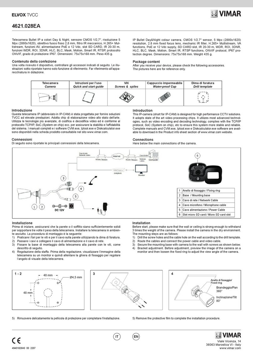
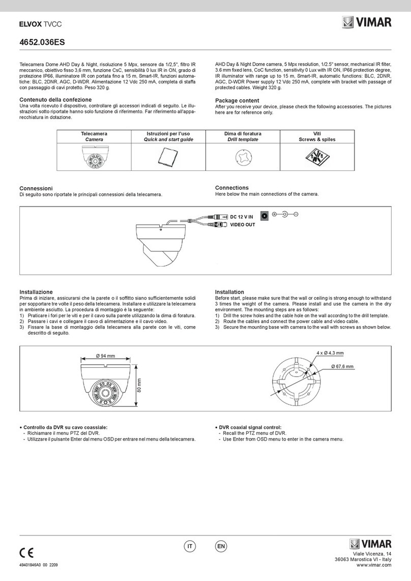
46226.312FM
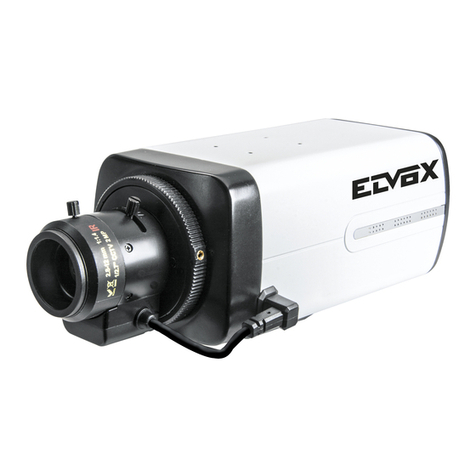
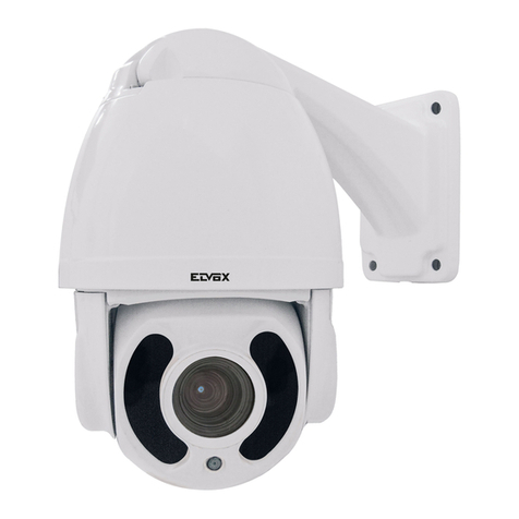
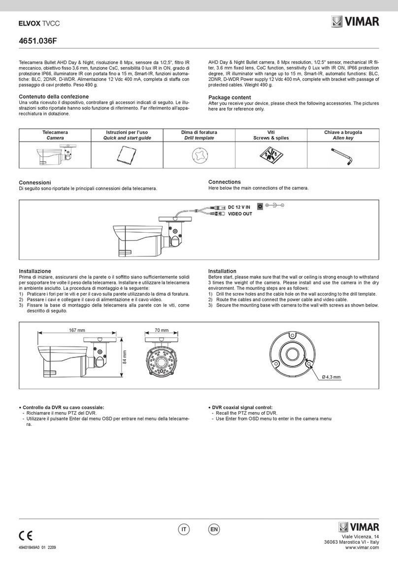
Telecamera Dome IP a colori Day & Night, sensore CMOS 1/2,5", risoluzione 8 Mpx
(3804x2160), obiettivo varifocale motorizzato 3,3-12 mm, filtro IR meccanico, H.265 e H.264
Multistream, alimentazione PoE o 12 Vdc, slot SD CARD, IR 20- 30 m, CVBS, Audio IN/OUT,
funzioni WDR, HLC, BLC, ROI, 3DNR, Mask, Motion, DC-Iris, Smart IR, RTSP, protocollo
ONVIF, grado di protezione IP66 e IK10. Dimensioni: Ø 150x114 mm. Peso 1260 g
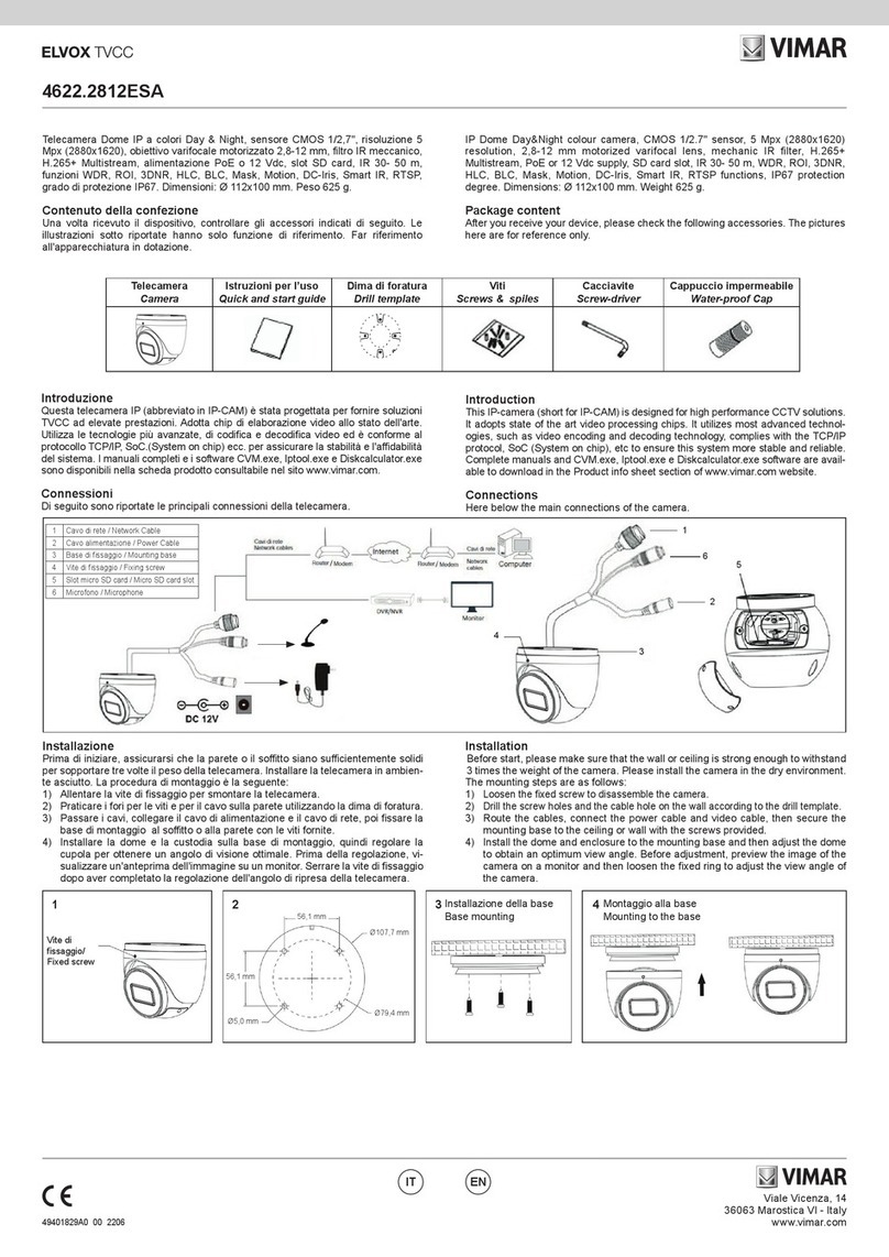
Contenuto della confezione
Una volta ricevuto il dispositivo, controllare gli accessori indicati di seguito.Le illu-
strazioni sotto riportate hanno solo funzione di riferimento. Far riferimento all'appa-
recchiatura in dotazione.
Package content
After you receive your device, please check the following accessories.
The pictures here are for reference only.
Introduzione
Questa telecamera IP (abbreviato in IP-CAM) è stata progettata per fornire soluzioni
TVCC ad elevate prestazioni. Adotta chip di elaborazione video allo stato dell'arte.
Utilizza le tecnologie più avanzate, di codica e decodica video ed è conforme al
protocollo TCP/IP, SoC.(System on chip) ecc. per assicurare la stabilità e l'adabilità
del sistema. I manuali completi e i software CVM.exe, Iptool.exe e Diskcalculator.exe
sono disponibili nella scheda prodotto consultabile nel sito www.vimar.com
Introduction
This IP-camera (short for IP-CAM) is designed for high performance CCTV solu-
tions. It adopts state of the art video processing chips. It utilizes most advanced
technologies, such as video encoding and decoding technology, complies with the
TCP/IP protocol, SoC (System on chip), etc to ensure this system more stable and
reliable. Complete manuals and CVM.exe, Iptool.exe e Diskcalculator.exe software are
available to download in the Product info sheet section of www.vimar.com website.
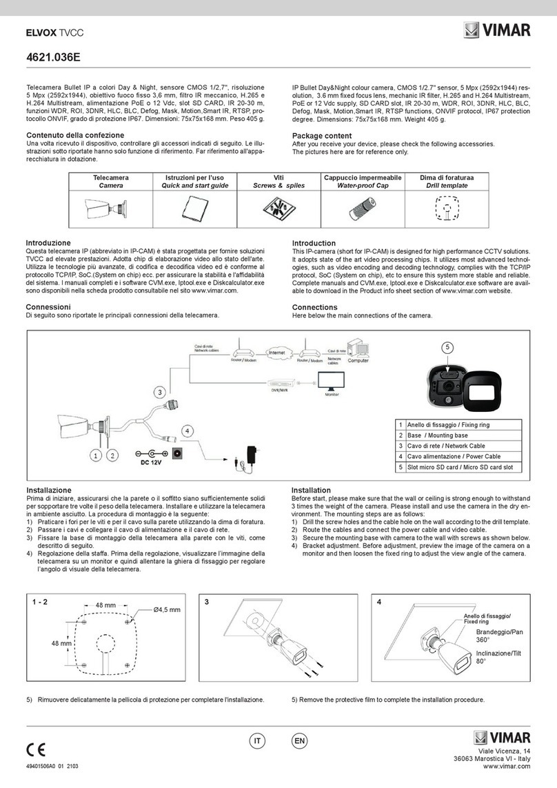
Connessioni
Di seguito sono riportate le principali connessioni della telecamera
ENIT
IP Dome Day&Night colour camera, CMOS 1/2,5" sensor, 8 Mpx (3804x2160) resolution,
3,3-12 mm motorized varifocal lens, mechanic IR filter, H.265 and H.264 Multistream, PoE
or 12 Vdc supply, slot SD CARD, IR 20- 30 m, CVBS, Audio IN/OUT, WDR, HLC, BLC, ROI,
3DNR, Mask, Motion, DC-Iris, Smart IR, RTSP functions, ON/VIF protocol, IP66 and IK10
protection degree. Dimensions: Ø 150x114 mm. Weight 1260 g
Connections
Here below the main connections of the camera
1 Cavo di rete / Network Cable
2 Cavo alimentazione / Power Cable
3Cavo cue / Headphone Cable
4 Uscita video / Video output
5 Ingresso-uscita allarme / Alarm input-output
6 Cavo RS485 / RS485 cable
7 Cavo alimentazione / Power cable
8 Slot per cheda TF / TF Card slot
9 Foro per il reset / Reset Hole
10 Porta CVBS/DC IN per test
CVBS/DC IN port for testing
Installazione
Prima di iniziare, assicurarsi che la parete o il sotto siano sucientemente solidi
per sopportare tre volte il peso della telecamera. Installare e utilizzare la telecamera
in ambiente asciutto. Si consiglia di riposizionare il copri obiettivo entro 4 ore dalla
sua rimozione. La procedura di montaggio è la seguente:
1) Allentare le viti per aprire la cupola inferiore, quindi allentare la vite di bloccag-
gio per rimuovere la base di montaggio.
2) Posizionare la dima per la foratura dove si intende ssare la telecamera, quindi
praticare i 4 fori per le viti e il foro per i cavi (nel caso si intenda far passare i
cavi attraverso la base di montaggio) in base alla dima.
3) Passare i cavi e collegarli. Quindi ssare la base di montaggio al sotto o pare-
te con le viti.
4) Fissare la telecamera alla base di montaggio con la vite di bloccaggio.
5) Regolazione dei tre assi. Prima della regolazione, visualizzare l’immagine della
telecamera su un monitor e quindi eettuarne la regolazione secondo le gure
seguenti per ottenere l’angolo migliore.
Installation
Before start, please make sure that the wall or ceiling is strong enough to withstand
3 times the weight of the camera. Please install and use the camera in the dry en-
vironment. You’d better install back the lens cover less than 4 hours after removing
it. The mounting steps are as follows:
1) Unscrewed the lock screw to open the lower cup and remove the base;
2) Position the drill template to x the camera and drill the 4 holes for screws and
cables (in case it is necessary to pass the cable through the mounting base)
3) Connect the cables and x with the screws the mounting base to the ceiling or
wall
4) Fix the camera with thelock screw to the mounting base
5) Adjustment of 3 axis. Before the adjustment, display the image to a monitor and
then adjust the camera according to the diagram below in order to achieve the
expected angle.
6) Regolazione della messa a fuoco e dello zoom.
Questo modello di telecamera, è dotato di lente motorizzata. Utilizzare i controlli
dell'interfaccia web per modicare le impostazioni di Fuoco e Zoom.
6) Adjustment the focusing and zoom. This type of camera is supplied of motorized
lens, it is necessary to connect to the web interface for setting the zoom and
focusing.
Zoom - Zoom +
Focus - Focus +
7) Screw the lower cup of the camera and remove softly the protection lm to
complete the installation procedure.
7) Fissare la cupola inferiore sulla telecamera con le viti e rimuovere
delicatamente la pellicola di protezione per completare l’installazione.
Telecamera
Camera
Istruzioni per l’uso
Quick and start guide
Dima di foratura
Drill template
Viti
Screws &
spiles
Cacciavite
Screw-driver
Cavo di connessione
CVBS e DC IN
CVBS & DC
in cables
Cappuccio impermeabile
Water-proof Cap
1 2 3 4 5
