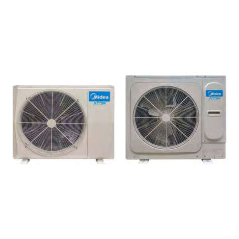
Data Aire DARC 03 Instruction manual


CONGRATULATIONS ON THE SELECTION OF A DATA AIRE PRECISION ENVIRONMENTAL CON-
TROL SYSTEM. PROPER INSTALLATION, OPERATION AND MAINTENANCE OF THIS EQUIP-
MENT WILL ENSURE YEARS OF OPTIMAL PERFORMANCE.
NOTE: This manual is intended to assist trained service personnel by providing neces-
sary guidelines for this particular equipment. Service to Data Aire units should be done
by qualied individuals with an adequate background in areas such as HVAC, electrical,
plumbing and electronics, as applicable.
WARNING: Service performed by unauthorized or unqualied technicians may void manu-
facturers’ warranties and could result in property damage and/or personal injury.
Special care should be given to those areas where these symbols
appear.
Data Aire, Inc. reserves the right to make design changes for the purpose of
product improvement or to withdraw any design without notice.

TABLE OF CONTENT
1.0 INTRODUCTION................................................................................................. 5
1.1 Model Identication ........................................................................................ 5
1.2 Inspection....................................................................................................... 5
1.3 Paperwork...................................................................................................... 5
1.4 Storage........................................................................................................... 6
1.5 Locating the Remote Heat Exchanger ........................................................... 6
1.6 Leg Assembly................................................................................................. 7
1.7 Rigging........................................................................................................... 7
1.8 Installation...................................................................................................... 8
1.8.1 Installation Checklist .................................................................................. 8
2.0 PIPING ............................................................................................................ 10
2.1 Discharge Lines ........................................................................................... 10
2.2 Liquid Lines.................................................................................................. 10
2.3 Field Piping, Remote Condenser Above Evaporator.....................................11
2.4 Field Piping, Remote Condenser Below Evaporator.....................................11
2.5 Condenser Connection Sizes....................................................................... 12
2.6 Leak Testing ................................................................................................. 13
2.7 Evacuation ................................................................................................... 13
3.0 ELECTRICAL CONNECTIONS......................................................................... 14
3.1 Electrical Service.......................................................................................... 14
3.2 Nameplate Ratings....................................................................................... 14
3.3 Grounding .................................................................................................... 14
3.4 Voltage Tolerance......................................................................................... 14
3.5 Phase........................................................................................................... 15
3.6 Auxiliary Control Wiring................................................................................ 15
3.7 Wiring Diagrams........................................................................................... 15
4.0 CHARGING....................................................................................................... 16
4.1 Fan Speed Control/Fan Cycling................................................................... 16
4.2 Ambient Sensing Thermostats ..................................................................... 16
4.2.1 Typical Ambient Thermostats Factory Settings........................................ 16
4.3 Charging with Fan Speed Control................................................................ 17
4.3.1 R-410a – Charging/Installation Work Procedures.................................... 18
4.4 Flooded Systems ......................................................................................... 18
4.4.1 Charging Flooded Systems...................................................................... 18
4.5 Refrigerant Handling .................................................................................... 19

4.6 Condenser with EC Motor Axial Fan(s) (Option) .......................................... 19
4.6.1 EC Motor Speed Adjustments.................................................................. 19
5.0 WARRANTY...................................................................................................... 20
6.0 PREVENTIVE MAINTENANCE ........................................................................ 20
6.1 Maintenance Functions................................................................................ 20
6.2 Electronically commutated (EC) Fan Trouble Shooting ............................... 20
6.3 Coil Cleaning................................................................................................ 20
6.3.1 When to Clean ......................................................................................... 20
6.3.2 What to Use ............................................................................................. 20
6.3.3 How to Clean ........................................................................................... 21
7.0 LINE SIZES....................................................................................................... 21
8.0 CONTACT DATA AIRE ...................................................................................... 22

5 • Air Cooled Condenser User Manual
1.0 INTRODUCTION
The Data Aire air-cooled condenser is low-prole direct-drive propeller or axial fan-type heat ex-
changer unit suitable for mounting outdoors. It provides for the heat rejection of either one or two
separate refrigeration circuits, matching heat rejection capacity varying with the outdoor ambient
temperatures and with each corresponding compressors heat rejection requirements. Constructed
with an aluminum cabinet and a copper-tube aluminum n coil, the unit is quiet and corrosion re-
sistant. The condenser is quickly and easily installed, because all internal wiring is completed at
the factory with only electrical connections to be made at the job site. All electrical connections and
controls are enclosed in an integral weatherproof electrical control section of the condenser.
1.1 ModelIdentication
1.2 Inspection
This Data Aire unit has been factory run tested and has passed a comprehensive inspection prior to
packaging and shipment ensuring it arrives in excellent condition. However, shipping damage can
occur and a visual inspection of the outer crating immediately upon delivery should be performed.
Note any external damage or other transportation damage on the freight carrier’s forms. Inspect the
unit itself for internal damage. A claim should be led with the shipping company if the equipment
is damaged or incomplete.
Loose items such as remote control panels, disconnect switch handles or other items are packed
inside the unit. Refer to the yellow shipping tag located on the door for details.
NOTE: Freight damage claims are the responsibility of the purchaser. Action to recover
losses should be led immediately. Please notify factory personnel of any claims.
1.3 Paperwork
Each Data Aire unit ships with a start-up sheet that should be completed during installation. Return
the completed startup sheet to the factory to validate the warranty. Also included in the paperwork
is a warranty/information packet that provides important wiring diagrams, specic component lit-
erature, warranty registration cards and other valuable paperwork including a copy of this Instal-
lation, Operation and Maintenance Manual (IOM). A yellow tag is attached to the outside panel to
indicate articles that may have been packaged and shipped loose within the unit that are not factory
mounted.

6 • Air Cooled Condenser User Manual
NOTE: It is the responsibility of the installing contractor to return the start-up sheet and
warranty registration card to Data Aire for proper activation of the unit warranty. Failure
to do so may cause delays and in some cases void the warranty.
WARNING: This equipment may contain substance that has been deemed harmful
to public health and the environment. Venting of refrigerants to the atmosphere is
illegal. Refrigerant recovery devices must be used when installing and/or servicing
these types of products.
1.4 Storage
Data Aire equipment comes ready for immediate installation. However, in some instances, it may
be necessary to store the equipment for a period of time. If you must store the equipment it should
be done in a dry area, out of the weather, protected from freezing temperatures, protected from
damage by other equipment in storage, or transportation equipment. Avoid stacking and frequent
relocation.
If equipment is stored for longer than 30 days special precautions must be taken to avoid coil dam-
age. All coils should be charged and sealed with a low pressure (less the 25 PSIG) inert gas, such
nitrogen. This prevents contaminants from entering the coils. When the seal is broken at installa-
tion, the rush of escaping gas veries the coil is still leak free. If coils are not charged and sealed,
condensation mixes with air pollutants forming a weak acid and over time can cause pinhole leaks
to develop in coil tubes.
When equipment is installed after storage, caution should be taken to inspect and replace damaged
components, if required. All moving parts should be hand tested to ensure they are free and clear
prior to start-up.
1.5 Locating the remote heat exchanger
Remote air-cooled condensers (i.e., heat exchangers) should be located in secure areas where
service is easily accessible. Areas where public access is available should be avoided. Avoid areas
that contribute to ice and snow accumulation. The condenser may need to be elevated to ensure it is
above the snow line in certain regions of the country. Condensers should be located in clean areas
free from debris or foreign matter that could block the coil surface. Avoid areas of hot air or fume
exhaust. Condensers should not be located near steam vents.
Figure 1

7 • Air Cooled Condenser User Manual
Condensers should not be closer than 36 inches from a wall or any obstruction. With proper clear-
ance on all other sides units can be placed side by side. Additional units should be placed no closer
than 48 inches apart, see Figure 1. Avoid air recirculation conditions that could be caused by walls,
screening, etc. Do not connect ductwork to the coil inlet or fan outlet. Keep fan discharge away
from building air intakes.
The remote heat exchanger must be located in an area that will ensure airflow into and out of the
heat exchanger plus adequate service access clearance. Short circuiting of the airflow or the in-
take of warmer air from another unit will seriously degrade the performance of the air-cooled heat
exchanger.
Do not locate the heat exchanger in a location that is bordered by tall obstructions (i.e. higher than
10 feet) on no more than two sides. See Figure 1 for minimum clearance from obstructions and
between units. With proper clearance on all sides, two units can be placed side by side. Additional
units should be placed at least 48 inches apart.
Noise factors should be considered when locating an air-cooled heat exchanger. Proximity to win-
dows, walls and surrounding structures can cause objections by the occupants. An acoustical ex-
pert should be consulted when noise is of a particular concern.
Avoid installing units near occupied spaces, above or outside utility spaces and corridors whenever
possible in order to reduce sound transmission and/or vibration to occupied spaces. Refrigerant
piping should be flexible enough to prevent transmission noise or vibration from the unit. Isolation
hangers should be used to prevent the transmission of vibration on all suspended (from the building)
refrigerant lines.
Air-cooled condensers should be placed at a level that is higher than the indoor evaporator. It is not
recommended to mount the condenser more than 10 feet below the evaporator. Excessive liquid
line pressure drop can cause poor evaporator performance.
1.6 Leg Assembly
The legs must be unbolted from their collapsed shipping position and extended prior to placing the
unit on its pad. Each leg extends down approximately 18” and reattaches using the same bolts.
NOTE: Failure to extend the legs will result in poor air distribution over the cooling coil
resulting in signicant capacity reduction and system failure.
Concrete pads are often used to provide support for the heat exchanger when set on the ground.
Bolt holes in the bottom of each leg can be used to anchor the unit. Units mounted on the roof
should be placed on rails designed to distribute the unit weight. Standard practices and local codes
should be followed in either instance.
1.7 Rigging
Outdoor condensers should be moved to their mounting location (typically rooftop) using a crane or
fork lift. Each fan section has heavy gage, steel leg supports with lifting holes at the top.

8 • Air Cooled Condenser User Manual
Do not lift with a choke sling around the unit. Spreader bars are recommended for lifting multiple fan
units (See Figure 2). Under no circumstances should the coil headers or piping be used for lifting
the unit. Ideally, the unit should be kept in its shipping crate until it is ready to be set in place.
WARNING: Use care when moving. Improper handling could result in injury. Proper
care should be taken when uncrating the unit. The packaging has wrapping bands with
sharp edges that are under tension, crating has staples and splinters. Proper protective
equipment should be worn by qualied personnel.
Figure 2
1.8 Installation
NOTE: There is no intent on the part of Data Aire, Inc. to dene local codes or statutes
which may supersede common trade practices. The manufacturer assumes no respon-
sibility for their interpretation. Consult local building codes and the National Electrical
Code (NEC) for special installation requirements.
1.8.1 Installation Checklist
As a precaution, review the following checklist to ensure proper operation:
• Check for any damage
• Check all wiring connections
WARNING: When preparing the equipment, proper care should be taken when uncrat-
ing the unit. The packaging has wrapping bands with sharp edges that are under ten-
sion, crating has staples and splinters. Proper protective equipment should be worn by
qualied personnel.
● Remove the metal strapping bands
● Remove the wooden crating
● Remove the protective plastic covering
WARNING: Before removing from the packaging inspect the unit for any damage.
Report any damage to the carrier and le a damage claim.

9 • Air Cooled Condenser User Manual
Only qualied and experienced service technicians should perform installation and maintenance on
this product. Equipment damage and personal injury can result from improper piping installation,
leak checking and improper handling.
This equipment is designed to operate properly and produce rated capacities when installed in ac-
cordance with industry standards. Failure to meet the following conditions could result in voiding
the warranty:
• System piping must be installed following industry standards for good piping practices
• System must be thoroughly leak checked before initial charging
• System power supply must meet voltage tolerance (see section 3.4)
• All controls and safety devices properly connected per wiring diagram
• Factory installed wiring must not be changed without written factory approval
Additionally, the refrigerant piping must comply with local code. After piping is completed all joints
(and connections) should be leak tested.

10 • Air Cooled Condenser User Manual
2.0 Piping
Refer to the Line Size chart (7.0 LINE SIZES) for a guideline to sizing refrigerant lines. The ultimate
responsibility for line size selection is that of the installing contractor or project engineer. Data Aire
does not assume this responsibility. The chart covers distances up to 200 equivalent feet. For in-
stallations greater than this distance refer to ASHRAE or similar references.
Note: Standard piping practice must be used to ensure proper oil return and ecient
operation. The interconnecting lines to the remote air-cooled condenser must be in-
stalled by a qualied refrigeration mechanic.
• Only use refrigerant grade copper tubing (ACR1 preferred)
• Soft solder joints are not acceptable
• Purge dry nitrogen through the lines while brazing
• Do not leave dehydrated piping or components open to atmosphere any longer than is re-
quired
Welded or sweat joints should be used. Piping must be supported within 18 inches of the inlet and
outlet connections on the units.
2.1 Discharge Lines
Discharge lines (also called hot gas lines) should be trapped at the top (inverted) and the bottom.
In addition, a trap should be installed for every 15 to 20 feet of vertical rise. Discharge line check
valves are highly recommended on all installations. Check valves should be installed 6 to 10 feet
from the compressor. See Figure 3
Proper design will minimize refrigerant pressure drop and will maintain sucient gas velocity to
carry oil through the condenser. Discharge line pressure drop should not exceed 6 PSI. Recom-
mended gas velocity for proper oil return is 1,000 FPM. Slope horizontal lines downward in the
direction of refrigerant flow (1/2” for every 10 feet of line length).
2.2 Liquid Lines
Liquid line size is determined by pressure drop and velocity. The liquid line pressure drop for R-407C
should not exceed 5 PSI (35 kPa) or 9 PSI (62 kPa) for R-410A. The recommended liquid velocity
should be between 200 and 300 FPM (1 to 1.5 m/sec). To avoid excessive liquid line pressure drop,
the air cooled condenser should be located above or at the same level as the evaporator. Condenser
installations more than 15 feet below the evaporator are not recommended. Insulation of liquid lines
is not required but can be useful in preventing excessive sub-cooling or flashing on long exposed
pipe runs.
1 The American refrigeration industry uses dierent copper pipe call ACR (air conditioning and refrigeration eld services) pipe, which is
sized directly by its outside diameter (OD) and a type letter indicating wall thickness. ACR pipe is manufactured without processing oils that would
be incompatible with the oils used to lubricate the compressors in the HVAC system

11 • Air Cooled Condenser User Manual
2.3 Field Piping, Remote Condenser Above Evaporator
Figure 3
2.4 Field Piping, Remote Condenser Below Evaporator

12 • Air Cooled Condenser User Manual
Note: Field connections at the indoor evaporator section and remote condenser will not
necessarily be the same as the eld pipe size required. These could vary signicantly.
2.5 Condenser Connection Sizes
CONDENSER CONNECTION SIZES – Single Circuit
Standard
Fans
Discharge
(Hot Gas) Line
Liquid
Line EC Fans
Discharge
(Hot Gas) Line
Liquid
Line
DARC 03 1/2” 1/2” GHRC 011 1/2” 1/2”
DARC 05 1/2” 1/2” GHRC 018 1/2” 1/2”
DARC 07 1-1/8” 7/8” GHRC 025 1-1/8” 7/8”
DARC 09 1-1/8” 7/8” GHRC 032 1-1/8” 7/8”
DARC 11 1-1/8” 7/8” GHRC 039 1-1/8” 7/8”
DARC 15 1-1/8” 7/8” GHRC 053 1-1/8” 7/8”
DARC 17 1-3/8” 7/8” GHRC 060 1-3/8” 7/8”
DARC 21 1-3/8” 7/8” GHRC 074 1-3/8” 7/8”
CONDENSER CONNECTION SIZES – Dual Circuit
Standard Fans
Discharge
(Hot Gas) Line
Liquid
Line EC Fan(s)
Discharge
(Hot Gas) Line
Liquid
Line
DARC 07 1-1/8” 7/8” GHRC 025 1-1/8” 7/8”
DARC 09 1-1/8” 7/8” GHRC 032 1-1/8” 7/8”
DARC 11 1-1/8” 7/8” GHRC 039 1-1/8” 7/8”
DARC 15 1-1/8” 7/8” GHRC 053 1-1/8” 7/8”
DARC 17 1-3/8” 7/8” GHRC 060 1-3/8” 7/8”
DARC 21 1-3/8” 7/8” GHRC 074 1-3/8” 7/8”
DARC 24 1-3/8” 7/8” GHRC 084 1-3/8” 7/8”
DARC 28 1-3/8” 7/8” GHRC 099 1-3/8” 7/8”
DARC 30 1-3/8” 7/8” GHRC 106 1-3/8” 7/8”
DARC 37 1-5/8” 1-1/8” GHRC 130 1-5/8” 1-1/8”
DARC 40 1-5/8” 1-1/8” GHRC 141 1-5/8” 1-1/8”
DARC 44 1-5/8” 1-1/8” GHRC 155 1-5/8” 1-1/8”
DARC 50 1-5/8” 1-1/8” GHRC 176 1-5/8” 1-1/8”
DARC 57 (DW)21-3/8” 7/8” GHRC 201 1-3/8” 7/8”
DARC 61 (DW)21-3/8” 7/8” GHRC 215 1-3/8” 7/8”
DARC 75 (DW)21-5/8” 1-1/8” GHRC 264 1-5/8” 1-1/8”
DARC 80 (DW)21-5/8” 1-1/8” GHRC 281 1-5/8” 1-1/8”
DARC 88 (DW)21-5/8” 1-1/8” GHRC 310 1-5/8” 1-1/8”
DARC 100 (DW)21-5/8” 1-1/8” GHRC 352 1-5/8” 1-1/8”
2 DW - double wide condenser

13 • Air Cooled Condenser User Manual
2.6 Leak Testing
NOTE: With any connection there is risk of leakage. Leakage could result in damage.
Leakage can be a result from improper installation and/or practices.
No installation is complete until the entire system has been thoroughly checked for leaks. This
includes checking the refrigerant tubing, flare ttings, pressure controls, Schrader ttings and com-
pressor Rotalock service valves.
With recent changes in the handling and recovery of refrigerant, it is not permissible to release
refrigerant into the atmosphere. Many leak-test methods recommended in the past are no longer
possible. Current standard practices must be used.
Pressurize the system circuit(s) to 150 PSIG (1034 kPa) using dry nitrogen with a trace of refriger-
ant. Check the entire system for leaks with a suitable leak nder (per local code) including but not
limited to all braze joints, caps, ttings and flare nuts on both eld and factory furnished compo-
nents. After completion of leak testing, release test pressure and pull a vacuum on the system.
NOTE: Tightening of tting and valves is the responsibility of the installing contractor.
2.7 Evacuation
Evacuate the refrigerant lines, condenser coil evaporator coil to 300 microns or lower (micron gauge
and 2-stage vacuum pump are required). Valve o and turn OFF the vacuum pump and wait at least
20 minutes to make sure the micron gauge reading does not go back above 500 microns. If it does,
restart the vacuum pump and evacuate until the system reaches 300 microns. If the system still
does not hold the vacuum below 500 microns the system needs to be rechecked for leaks.
NOTE: Do not apply power to the compressor (i.e., run the compressor) when under
a vacuum.

14 • Air Cooled Condenser User Manual
3.0 ELECTRICAL CONNECTIONS
WARNING: The Data Aire cooling unit must be connected by a licensed and qualied
electrician. Risk of electrical shock could result in injury or death. Disconnect all remote
electrical power supplies prior to working on the unit.
NOTE: Disconnect switches are optional. The disconnect switch when turned OFF will
de-energize the high voltage.
WARNING: Before proceeding with the electrical connections, make certain that the
volts, hertz and phase correspond to that specied on the unit electrical nameplate.
Use copper conductors only.
3.1 Electrical Service
Check to be sure the service provided by the utility is sucient to handle the additional load imposed
by this equipment. Units with secondary heat exchangers will require a separate power source and
eld-provided, interconnecting control wires.
3.2 Nameplate Ratings
Refer to the unit electrical nameplate for equipment electrical requirements. Minimum circuit am-
pacity (MCA) also known as wire sizing amps, will dictate the minimum required wire gauge.
Maximum overcurrent protection (MOP) device amps will dictate the maximum circuit breaker or
fuse size.
3.3 Grounding
The unit cabinet must have an uninterrupted true earth ground. An electrical ground wire of ad-
equate size must be connected to the ground lug provided inside the main electrical box.
3.4 Voltage Tolerance
The supply voltage to the unit must be within tolerance; -5% to +10% for 208-230 voltage, +10% for
460 volts as indicated on the unit electrical nameplate. Phase to phase imbalance must not exceed
3%. The local utility company should be contacted for improper line voltage. Deviation from voltage
ratings can cause premature failures and possibly void unit warranties.
WARNING: Check the wiring connections in the unit control panel to ensure they are
tight. Screw terminals may become loose in transit. Tightening of wiring connections
is the responsibility of the installing contractor.

15 • Air Cooled Condenser User Manual
3.5 Phase
The air-cooled condenser may be ordered as three-phase but the individual fan motors are single
phase and will only run in one direction. Check operation by placing a momentary jumper across
eld terminals #39 and #40 (refer to unit electrical wiring diagram). This energizes the control circuit.
If the fans do not run:
• The head pressure has not exceeded the require discharge pressure. The rst fan (with fan
speed control) reacts to head pressure
• Multiple fan units also have a pressure control on the second motor
3.6 Auxiliary Control Wiring
Auxiliary control wiring for secondary heat exchangers (i.e., condensers) is accomplished by con-
necting two 18 gauge wires from the electrical box of the indoor evaporator to the electrical box of
the remote heat exchanger. Follow the wiring diagrams for each of these pieces of equipment.
On most evaporator sections the interface connections will be on terminals #46 and #47. On older
units with the DAP-II controller, the terminals are #42 and #43. On most remote heat exchangers
the terminals will be #39 and #40.
All control wiring on Data Aire equipment is 24 VAC or less. Refer to the wiring diagrams.
WARNING: Check the wiring connections in the unit control panel to ensure they are
tight. Screw terminals may become loose in transit. Tightening of wiring connections
is the responsibility of the installing contractor.
3.7 Wiring Diagrams
Every Data Aire condenser comes with a wiring diagram. These diagrams are ladder type schemat-
ics intended for service personnel. The intent is to allow the technician to understand the wiring
details associated with the electrical components and how they interface with the controls as well
as peripheral equipment (including secondary heat exchangers).
The wiring diagram in the evaporator will indicate eld interface terminals to the secondary heat
exchanger. The internal wiring of the heat exchanger is found on a separate diagram which can be
found on the inside cover of the heat exchanger electrical box. Both diagram types are also placed
inside the shipping/warranty packet secured in the evaporator section.

16 • Air Cooled Condenser User Manual
4.0 CHARGING
4.1 Fan Speed Control/Fan Cycling
Data Aire air-cooled condensers (DARC) is equipped with the latest upgrade to control the high side pressure
of the refrigeration system. The Fan Speed Control (FSC) is a single-phase condenser fan speed controller that
is compact, weather-resistant, and durable speed control for single-phase, permanent-split capacitor (PSC)
motors used in a wide variety of low-ambient refrigeration and air conditioning condenser applications. The
FSC is designed to allow additional features and application flexibility.
On single fan condensers this is the only means of fan speed control. Multiple fan condensers are
provided with fan speed control on the rst motor (nearest the header) and ON/OFF operation for
all other motors. The FSC is pre-programmed at the factory and there is no need to adjust the unit
in the eld. The rst fan will cycle with the head pressure of the unit.
Refrigerant Starting Pressure Full Speed Pressure
R-410a 320 PSIG 400 PSIG
R-407c 220 PSIG 285 PSIG
When the condenser load exceeds the output capacity of the rst fan (controlled by the FSC), the
second fan will turn ON to full speed and the rst fan will modulate, as required to maintain the
head pressure of the unit. This allows the condenser load to be modulated by the cooling eect of
two fans instead of just one.
4.2 Ambient Sensing Thermostats
On condensers with more than two fans, the additional motors (subsequent to the rst and second
motors) are cycled by means of ambient temperature sensing thermostats. These thermostats have
a capillary tube with remote sensing bulb. They function best with the sensing bulb is mounted
below the coil, away from exposure to direct sun light and the bulb in the vertical position. An in-
struction set comes as part of a mounting kit that includes a sheet metal bracket, mounting clamps
and TEK screws. This includes directions for eld mounting and adjustment. The ambient sensing
thermostats are adjusted to maintain a desired head pressure range shown below:
Refrigerant Head Pressure
R-410a 340 to 400 PSIG
R-407c 230 to 285 PSIG
4.2.1 Typical Ambient Thermostats Factory Settings
AMBIENT THERMOSTATS FACTORY SETTINGS
Number of
Fans
Motor Number
1
Motor Number 2 Motor Number
3
Motor Number
4
Motor Number
5
1 FSC N/A N/A N/A N/A
2 FSC Pressure Control N/A N/A N/A
3 FSC Pressure Control 50°F N/A N/A
4 FSC Pressure Control 75°F 50°F N/A
5 FSC Pressure Control 85°F 75°F 50°F
As the ambient air temperature decreases the capacity of the condenser increases. The capacity
increase is directly proportional to the temperature dierence (TD) between the condensing tem-

17 • Air Cooled Condenser User Manual
perature and the ambient air temperature entering the condenser coil. Air-cooled condensers are
required to operate over a wide range of ambient air temperatures. Provisions must be made to
maintain the overall system balance. Air-cooled condensers tend to run at low head pressure when
operating in low ambient condition. Low head pressure can cause poor expansion valve operation
and poor system performance.
4.3 Charging with Fan Speed Control
As previously noted, the standard Data Aire air-cooled condenser (DARC) comes equipped with fan
speed control on the lead motor (motor number 1, nearest the header). After eld refrigerant pip-
ing is properly completed, connect a refrigerant drum to the low side of the system and charge with
vapor (refer to Section 2.5 Leak Testing and Section 2.6 Evacuation prior to charging the system).
Connect the refrigerant drum to the high side and charge with liquid. Charge with approximately
2.55 pounds per nominal ton. Make sure all hoses are properly purged.
NOTE: Before starting the compressor(s) the crankcase should be energized for a
minimum of 12 hours to reduce the possibility of liquid slugging on start-up. Failure to
energize the crankcase heater could result in compressor damage.
Use the manual override switches (evaporator motor and compressor) on the unit mounted control-
lers (dap4, DAP-III or DAP-II) to switch the units to the ON position (all automatic control will be
disabled but safety switches will remain functional).
Start the evaporator fan and then the compressor. Check the liquid line sight glass to get a feel for
the approximate charge. Bubbles in the sight-glass are not unusual at this point. It is more likely that
more refrigerant will be required to complete the charging procedure.
Adjust the refrigerant charge until the system measures 8 to 10°F of sub-cooling . For system with
Electronic Expansion Valves (EEV), the superheat setpoint defaulted is 6°F and should be between 5
to 10°F. Units with dual refrigerant circuits should have both compressors energized. The unit should
be allowed to stabilize for at least 20 minutes before meaningful measurements can be recorded.
After the system is allowed to stabilize, a few key measurements should be noted. The superheat
should be measured at the compressor suction line, at least 6 inches away from the compressor.
KEY MEASUREMENTS
Refrigerant Discharge Head
Pressure5
Sub-Cooling6
(depending on ambient condi-
tions)
Suction Pressure7Superheat8
R-410a 340 to 415 PSIG 8 to 10°F 104 PSIG or greater 8 to 15°F
R-410a With Elec-
tronic Expansion Valves 340 to 415 PSIG 8 to 10°F 104 PSIG 5 to 10°F
R-407c 245 to 285 PSIG 8 to 10°F 52 PSIG or greater 8 to 15°F
5 Discharge pressure (also called high side pressure or head pressure) is the pressure generated on the output side of a gas compressor
in a refrigeration of air conditioning system. The discharge pressure is aected by several factors: size and speed of the condenser fan, condition
and cleanliness of the condenser coil, and the size of the discharge line.
6 The term subcooling refers to a liquid existing at a temperature below its normal saturation temperature. Subcooling is normally used so
that when the cycling refrigerant reaches the thermostatic expansion valve, it is totally in liquid form, thus, allowing the valve to work properly.
7 In refrigeration and air conditioning systems, the suction pressure (also called the low-side pressure) is the intake pressure generated by
the system compressor while operating.
8 In refrigeration superheat is the amount of heat added to the refrigerant after it has changed from liquid to vapor state.

18 • Air Cooled Condenser User Manual
NOTE: Charging to a full liquid line sight-glass should never be the sole means of de-
termining the correct refrigerant charge. Other parameters such as superheat, suction
pressure, head pressure, sub-cooling and ambient air temperature are also important.
A system charged to a full sight-glass is often overcharged.
4.3.1 R-410a – Charging/Installation Work Procedures
The basic installation work procedures are the same as R-407c refrigerant. Since the working pres-
sure is 1.6 times higher than the conventional refrigerant, some of the piping, installation and tools
are special.
Special Service Equipment
• High pressure manifold gauge set
• High pressure recovery machine
• High pressure recovery tank (DOT 4BA400 or ABW400)
NOTE: R-410a and R-407c use Polyolester oil (POE) oil that is prone to absorbing
moisture. The system should never be left open to the atmosphere.
4.4 Flooded Systems
Flooded systems are units having refrigerant circuits with optional liquid receiver and head pressure
control (recommended for low ambient conditions). When the ambient temperature falls during cold
weather, the head pressure control valve will regulate the flow of refrigerant to ensure nearly con-
stant receiver pressure. The condenser is partially flooded with liquid refrigerant in cold weather. In
warm weather the extra refrigerant is stored in the receiver.
Data Aire units with optional receivers are either provided within the evaporator section (depending
on the unit size) or shipped loose for eld installation. The receiver includes heaters and thermostat.
A thermostat monitors temperature in the receiver and prevent overheating (overheating of receiv-
ers may cause the soft plug to blow and loss of refrigerant charge).
4.4.1 Charging Flooded Systems
Flooded systems require more refrigerant than condensers with fan speed control. With the unit
under a vacuum, add liquid refrigerant directly into the receiver. Make sure all hoses are properly
purged.
Use the manual override switches (evaporator motor and compressor) on the unit mounted control-
lers (dap4, DAP-III or DAP-II) to switch the units to the ON position (all automatic control will be
disabled but safety switches will remain functional).
Hook up charging gauges to the suction line. If the receiver (head) pressure is below the pressure
shown in the chart below for the required refrigerant, block part of the condenser coil surface until
the pressure rises to the specied pressure or higher. During extremely cold weather all the con-
denser fans may have to be de-energized to maintain the desired receiver (head) pressure.
Refrigerant Receiver (Head) Pressure
R-410a 342 PSIG
R-407c 242 PSIG 10
Observe the sight-glass on the receiver. Add refrigerant liquid through the suction line until the level
of liquid in the receiver is approximately 1/3 from the bottom of the sight-glass which is about 80%

19 • Air Cooled Condenser User Manual
full. The sight-glass on outdoor receivers will be dicult to observe however, this step is required for
proper charging.
WARNING: When adding refrigerant through the suction line it is imperative that the
refrigerant is meter carefully to the compressor. Charging a liquid into the suction line
too rapidly can cause damage to the compressor.
Units with dual refrigerant circuits should have both compressors running. The unit should be al-
lowed to stabilize for 20 minutes before meaningful measurements can be recorded.
After the system is allowed to stabilize, the superheat at the compressor suction line (at least 6
inches away from the compressor) should be 8 to 15°F. For system with electronic expansion
valves, the superheat setpoint is defaulted at 6°F and should be between 5 to 10°F. Remove the
block from the condenser coil. If the ambient air temperature while charging is below 60°F, some of
the refrigerant will be backed up in the condenser coil, causing the liquid level in the receiver to drop.
NOTE: Charging to a full liquid line sight-glass should never be the sole means of de-
termining the correct refrigerant charge. Other parameters such as superheat, suction
pressure, head pressure, sub-cooling and ambient air temperature are also important.
A system charged to a full sight-glass is often overcharged.
4.5 Refrigerant Handling
The use of recovery/recycling units is required by the U.S. Environmental Protection Agency (EPA)
regulations. Technician who service and dispose of air conditioning and refrigeration equipment
must recover the refrigerant instead of venting it to the atmosphere.
Except for extremely small releases of refrigerant such as what occurs when disconnecting service
hoses (diminutive release), a technician who knowingly releases or vents refrigerant to the atmo-
sphere is in violation of this regulation. Freon purchases must be made by certied technicians and
have a valid EPA certication card.
4.6 Condenser with EC Motor Axial Fan(s) (Option)
Data Aire air-cooled condensers (GHRC) provided with optional axial Electronically Commutated
(EC) fan(s) provide variable speed control based on head pressure. The EC motor has all the re-
quired components to run at variable speeds.
The control system in a GHRC condenser allows all fans to modulate, as required, to maintain the
proper head pressure of the unit.
4.6.1 EC Motor Speed Adjustments
The EC motor varies its speed linearly based on a 0-10V input signal from the head pressure trans-
ducers. The fans are scaled per the following table:
Refrigerant Pressure Settings (PSIG)
Refrigerant Cut-in 100O F Full Speed
R-410a 319 370
R-407c 226 270

20 • Air Cooled Condenser User Manual
5.0 WARRANTY
NOTE: See separate warranty certicate and registration card that is supplied with
each unit as part of the paperwork package.
6.0 PREVENTIVE MAINTENANCE
The operating life of the condenser can be extended by following a simple preventive maintenance
schedule. This schedule will reduce the possibility of failure of components and unnecessary mal-
function of the system. Although the service technicians must be thoroughly familiar with the special
design features of this equipment before attempting any service or repair, an experienced techni-
cian can perform certain simple maintenance functions to ensure normal, trouble-free operation.
6.1 Maintenance Functions
Monthly
Inspect condenser for obstruction to the inlet air side of the coil.
Inspect the motor/fan blade assemblies to ensure the bearings are
free and the motor mounts and fan(s) are secure.
Seasonally
Inspect electrical components for loose wire connections.
Inspect contactor contacts for pitting.
Inspect fan motor(s).
In the winter, do not allow snow to accumulate or build-up around the
sides or underneath the coil.
Bi-annually Clean the condenser coil of all debris that could restrict air flow.
Annually Check all refrigerant lines and connections for leaks or any sign of oil.
6.2 Electronically Commutated (EC) Fan Troubleshooting
Refer to the EC fan manufacturer’s Operating Instructions for detailed instructions, critical safety
information and troubleshooting instructions for this product.
6.3 Coil Cleaning
Keeping the outdoor coils clean is an important factor in maintaining peak eciency, reliability and
long life of the equipment. It is much easier to keep up on frequent cleanings rather than wait until
heavy build up has occurred which may create head pressure problems with the evaporator units.
6.3.1 When to Clean
Normal conditions typically dictate cleaning twice a year, spring and fall. On-site or area conditions
such as cottonwood trees, construction, etc., can increase cleaning frequency. On your standard
monthly preventive maintenance schedule, a visual inspection of the coil is recommended to moni-
tor conditions.
6.3.2 What to Use
The best overall coil cleaner to use is plain water. If the coil has been maintained and cleaned at
regular intervals, water is sucient to remove dirt and debris from the ns. Heavy build up on the
exterior of the ns can be removed with a brush. Water pressure from a garden hose and sprayer
usually works well.
This manual suits for next models
47
Table of contents
Other Data Aire Air Conditioner manuals
Data Aire
Data Aire LCS User manual
Data Aire
Data Aire gForce Ultra Instruction manual
Data Aire
Data Aire DAMA-01 User manual
Data Aire
Data Aire gForce DX series User manual

Data Aire
Data Aire gForce Ultra User manual

Data Aire
Data Aire gForce Ultra User manual
Data Aire
Data Aire LCS User manual
Data Aire
Data Aire gForce GT series User manual
Popular Air Conditioner manuals by other brands

Friedrich
Friedrich Chill CP18 Installation and operation manual
York
York YNKFZC024-055BAADAFX owner's manual
Friedrich
Friedrich CCW06B10B operating instructions
Cruisair
Cruisair Zephyr Installation and operation manual
Airwell
Airwell AWSI-HDD018-H11 Service manual

Ocean Breeze
Ocean Breeze OBZ-10ESN owner's manual


