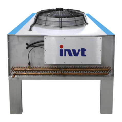
INVT VCS Series User manual

Preface
VcolSer Rack Air Conditioner
II
Preface-About the product and manual
[Manual purpose]
This manual introduces the main features, performance, and working principle
of the new generation of intelligent rack-mounted precision air conditioners and
provides users with information on usage, operation, and maintenance.
[User]
Technical Support Engineer
Maintenance Engineer
[Disclaimer]
1. Outside the free warranty period;
2. Disassemble or modify the product without authorization;
3. Violation of product operation or use specifications;
4. Man-made faults;
5. The product suffered losses caused by irresistible or other external factors on
the client-side.
[Note:Any of the above exemption clauses will not be covered by the warranty.]
[Related description]
1. This manual is provided with the product, please keep it in a safe place so that
you can check it at any time when you need it. In case this manual is
accidentally lost or damaged, please obtain it directly from the manufacturer
or local distributor;
2. This manual is written for VCS series air-cooled products, and the content
may not be applicable to other models;
3. Due to product version upgrades or other reasons, the content of this
document will be updated from time to time.
Unless otherwise agreed, this document is only used as a guide, and all reports,
information, and suggestions in this document do not constitute any express or
implied guarantee.
4. The copyright of this manual belongs to Shenzhen INVT Network Technology
Co., Ltd., and all rights are reserved. The content is subject to change without
notice.

CONTENTS
VcolSer Rack Air Conditioner
III
CONTENTS
Preface-About the product and manual.........................................................................................II
Chapter 1 General ..........................................................................................................................1
1.1 Products Introduction...........................................................................................................1
1.2 Operating Parameters and Requirements.............................................................................2
1.3 Type Description..................................................................................................................2
1.4 System Composition ............................................................................................................2
1.5 Product Specification ...........................................................................................................3
1.5.1 Dimensions and Net Weight..........................................................................................3
1.5.2 External Structure..........................................................................................................3
Chapter 2 Receiving.......................................................................................................................5
2.1 Transportation ......................................................................................................................5
2.2 Receiving..............................................................................................................................5
2.2.1 Receiving Process Suggestions .....................................................................................5
2.2.2 External Checking .........................................................................................................6
2.2.3 Unboxing.......................................................................................................................7
2.2.4 Internal Checking ..........................................................................................................7
2.2.5 Storage...........................................................................................................................8
Chapter 3 Installation.....................................................................................................................9
3.1 Installation Site.....................................................................................................................9
3.2 Installation Form..................................................................................................................9
3.3 Mechanical Installation......................................................................................................10
3.3.1 Install Indoor Machine.................................................................................................10
3.3.2 Install Outdoor Machine..............................................................................................11
3.3.3 Connecting Tube..........................................................................................................12
3.4 Electrical Installation..........................................................................................................16
3.4.1 Operating the Project...................................................................................................16
3.4.2 Matters Needing Attention ..........................................................................................16

CONTENTS
VcolSer Rack Air Conditioner
IV
3.4.3 Detection......................................................................................................................17
3.4.4 Graphical Representation ............................................................................................17
Chapter 4 Controller ....................................................................................................................18
4.1 Features ..............................................................................................................................18
4.2 Display (when optional).....................................................................................................18
4.3 Control Key........................................................................................................................19
4.4 Switch Operation................................................................................................................19
4.5 Status Query.......................................................................................................................20
4.6 User Settings ......................................................................................................................20
Chapter 5 Inspection and Debugging...........................................................................................23
5.1 Inspection...........................................................................................................................23
5.2 Nitrogen to Maintain Pressure............................................................................................23
5.3 Refrigerant Charging..........................................................................................................24
5.4 Lubricating Oil Supplement...............................................................................................25
5.5 Function Test......................................................................................................................25
5.6 System Debugging .............................................................................................................25
Chapter 6 Maintenance and Troubleshooting..............................................................................26
6.1 Daily Maintenance .............................................................................................................26
6.2 Common Troubleshooting .................................................................................................27
Annex ⅠElectrical Schematic Diagram of the Indoor Unit.....................................................30
Annex ⅡElectrical Schematic Diagram of the Outdoor Unit ..................................................31

Chapter 1 General
VcolSer Rack Air Conditioner
1
Chapter 1 General
Summary--This chapter mainly describes five aspects including product introduction, operating
parameters and requirements, type description, system composition, and product specifications.
1.1 Products Introduction
Products
The VCS series Rack Air Conditioner is a product highly suitable for the application scenarios
of micro-module products. It is embedded in a standard cabinet to achieve near-end cooling and
reduce the PUE value of the data center. It has the characteristics of high efficiency and energy
saving, easy installation, high integration, flexible combination, safety, and reliability.
Types
This product is divided into a variety of models with heating and humidification and without
heating and humidification. The main functions of the humidifier with heating are: refrigeration,
dehumidification, humidification, and heating; the humidifier without heating has only the cooling
and dehumidification functions.
Refrigerating capacity
The refrigeration levels of VCS series rack air conditioners are:3.5kW~12.5kW.
Features
1. High reliability, high sensible heat ratio, large air volume;
2. High-efficiency backward-inclined centrifugal EC fan design, with large air volume, high
efficiency, and low noise;
3. The well-designed and matched refrigeration system ensures optimal energy-saving
operation all-weather;
4. The rack-mounted design concept makes the layout application more flexible and exquisite;
5. Adopt R410A green environmental protection refrigerant, in line with international
environmental protection refrigerant requirements;
6. Adopt a large-area "V"-shaped evaporator design to make heat exchange faster and more
efficient;
7. The electronic expansion valve is used to accurately control the refrigerant flow, which can
save up to 30% of energy consumption;
8. Adopt international famous brand DC inverter compressor, its excellent quality guarantees
the unit's high efficiency and stability;
9. The use of high-quality refrigeration valves makes the operation more reliable;

Chapter 1 General
VcolSer Rack Air Conditioner
2
10. A variety of optional accessories, to provide users with a variety of options.
1.2 Operating Parameters and Requirements
Table 1-1 Operating parameters and requirements table
--
Item
Indoor
Outdoor
Operating Parameters
Temperature/T
0℃~45℃
-40℃~+45℃
Humidity /RH
5%~95%
——
Operating
Requirements
Altitude/M
Altitude <1000M, more than 1000M need to be derated
Power supply /V
220V±10%, 50±2Hz
1.3 Type Description
E.g.:Type——VCS003AH**
Figure 1-1 Naming rules for indoor units
Figure 1-2 Naming rules for outdoor units
1.4 System Composition
VCS series rack air conditioners are mainly composed of refrigeration system, control system,
ventilation system, humidification system, and heating system. The unit is mainly composed of the
following components:
1. Compressor. Using high-efficiency DC inverter compressor, matched with R410A
refrigerant, environmental protection and pollution-free;
2. Evaporator. Large area "V" or "/" type evaporator design, which makes heat exchange
faster and more efficient;
3. Expansion valve. Electronic expansion valve, wide adjustment range, precise flow
Air-cooled
Type
Front air supply
VCS Series Rack Air Conditioner
VCS
A
003
VCS
Single
Type
Formal type
Condenser
VCP
S
005
F
VCP
H
003
A
H
005
S
F
**
**
Internal code

Chapter 1 General
VcolSer Rack Air Conditioner
3
adjustment, high reliability of operation;
4. Heater. PTC heater, with fast heating speed and even heat;
5. Wet film humidification components (when optional). Adopt wet film evaporative
cooling technology, environmental protection, and energy-saving, low maintenance cost;
6. Filter drier. Protect the refrigeration system, make the system free of moisture, acid, and
solid impurities;
7. Compressor heating belt. Used to heat the oil sump of the compressor crankcase. The
heating belt must be energized for at least 12 hours before starting;
8. EC fan. To achieve step-less speed regulation of wind speed, wide adjustment range;
9. Air filter. Filter dust and impurities in the air to ensure the cleanliness of the environment;
10. Controller. Standard RS485 communication interface, support remote centralized control,
call self-start, password protection, timing on/off, etc.;
1.5 Product Specification
1.5.1 Dimensions and Net Weight
Table 1- 2 Dimensions and net weight
Product
Type
Dimension (mm)W×H×D
Net Weight (kg)
Indoor unit
VCS003AH**
442×220×8 00
26
Outdoor unit
VCP005SF
840×606×340
38
1.5.2 External Structure
The appearance and structure of the indoor unit and outdoor unit:
(Side view)(Front view)
Figure1- 1 VCS003AH

Chapter 1 General
VcolSer Rack Air Conditioner
4
(Top view)(Front view)
Figure 1- 2 VCP005S

Chapter 2 Receiving
VcolSer Rack Air Conditioner
5
Chapter 2 Receiving
Summary--This chapter mainly introduces the process and related precautions in the process of
product transportation and reception.
2.1 Transportation
Special Note
The VCS series Rack air conditioners contain mechanical, electrical and other equipment.
Improper transportation and handling may cause damage to the product and cause the equipment to
fail to operate normally. Please ensure the safety and quality of the product during transportation and
handling.
Precautions
Precautions related to transportation and handling:
1. Please try to choose a better transportation method (such as railway transportation,
shipping). When choosing automobile transportation, you should choose a road with better
road conditions to prevent excessive bumps;
2. The transportation environment and placement requirements should be implemented in
accordance with relevant requirements;
3. Please try to use mechanical handling tools when unloading and transporting;
4. Anti-collision, anti-drenching, etc.
Table 2- 1 Packaging dimensions and gross weight of VCS precision air conditioners
Type
Packaging Dimensions
(mm)W×D×H
Gross Weight(kg)
VCS003AH**
650×450×1050
32
VCP005SF
870×960×550
43
2.2 Receiving
Special Note
VCS series Rack Air Conditioners have passed strict quality assurance tests and inspections
before leaving the factory. Please check the equipment carefully when receiving the products to
ensure that the equipment has not been damaged during transportation.
2.2.1 Receiving Process Suggestions
In view of the fact that after the product arrives, users have two situations: immediate
installation and temporary non-installation. In order to provide users with a better receiving plan, the

Chapter 2 Receiving
VcolSer Rack Air Conditioner
6
following simulated receiving process is given for users' reference; please choose the best plan
according to the specific situation.
Flow Chart
The following figure 2-1 is a schematic diagram of the simulation of the receiving process, and
the specific content of each step is shown in this section.
Figure 2- 1 Schematic diagram of receiving process simulation
The figure shows the receiving process under two conditions, namely, condition Aand condition B:
A——Instant installation;
B——Delayed installation;
①——Arriving;
②——External Checking;
③——Carrying;
④——Unboxing;
⑤——Internal Checking;
⑥——Acceptance;
A:⑦——End Receiving.
B:⑦——Sealing;⑧——Storage;⑨——End Receiving.
2.2.2 External Checking
Transportation Checking
After arrival, check whether the transportation meets the transportation requirements.
Transportation requirements:
1. Keep out of the rain;
2. Place it upright;

Chapter 2 Receiving
VcolSer Rack Air Conditioner
7
3. Cannot be stacked;
4. Be careful of collisions.
[Note: The specific requirements shall prevail.]
External Checking
The content of the external inspection includes the outer packaging of the product and the
exterior of the product, etc.
Check Content:
1. Whether the outer packaging has been opened;
2. Whether the outer packaging has obvious damage and collision marks;
3. Whether the exposed parts of the equipment are damaged, such as fins are recessed, the
structure is deformed, and the topcoat is peeled off;
Related Tips
1. If you find that it has been opened, please check whether there is any information on the bill of
lading or other aspects; if not, please contact the relevant department;
2. If damage is found, please indicate the corresponding damage on the bill of lading and submit a
damage claim to the transportation company;
3. The above problems may cause damage to the production equipment and make the product
unable to be used normally. Please check carefully. If there is any problem, please contact INVT
service department.
2.2.3 Unboxing
Suggestion
1. It is recommended that the user move the product to a place as close as possible to the
installation site (or to the storage place) before unpacking;
2. When opening the box, it is recommended that the user consider the reusability of the box.
Related Tips
3. The product is packed in a carton, and the user must be careful when opening the box to
avoid damage to the equipment and malfunction due to improper operation;
4. Improper operation may cause damage to the equipment, which will invalidate the
manufacturer's warranty.
2.2.4 Internal Checking
Check Content:
1. After unpacking, please carefully check whether all the internal parts of the equipment are
complete and damaged;

Chapter 2 Receiving
VcolSer Rack Air Conditioner
8
2. Check whether the accessories are complete according to the packing list.
Related Tips
1. If any part is found to be missing or damaged during the inspection, it should be reported to
the carrier immediately; if any hidden damage is found, it should also be reported to the
carrier and product supplier;
2. If the packing list is not complete, please contact the relevant personnel of the product
supplier immediately.
2.2.5 Storage
After the user receives the product, please store it properly according to the following
requirements.
Table 2-2 Equipment storage requirements
Content
Requirements
Storage Environment
Clean、Safe
Temperature
-40℃~70℃
Humidity
<95%RH
Storage Time
The total transportation and storage time should not exceed 6 months, and the
performance needs to be re-calibrated if it exceeds 6 months.
Warning: 1. If the equipment has been unpacked, it must be repackaged according to the original
packaging requirements;
2. Exposure to the outside environment for a long time after the device is unpacked
may cause damage and invalidate the manufacturer's warranty.
警告
危险

Chapter 3 Installation
VcolSer Rack Air Conditioner
9
Chapter 3 Installation
Summary--This chapter mainly introduces the installation site, installation form, mechanical installation,
and electrical installation, etc.
3.1 Installation Site
In order to make the unit easy to install and run in the best condition, before the installation of the
equipment, users need to consider the relevant factors in the installation place to ensure that the room and
outdoor meet the requirements of use.
Consideration
1. Whether the equipment is convenient to enter the air-conditioned place, and whether the piping and
wiring are convenient;
2. Heat preservation and insulation treatment should be carried out in the air conditioning places to
minimize the heat load; Maintain positive pressure, prevent dust from entering through the gap, to
reduce the load of other heat and humidity, dust filtration;
3. Ensure that the air supply and return channels of air conditioning units are unobstructed;
[Note: The above factors are for reference only, please hire a professional engineering company to design according
to the relevant specifications according to the site conditions.]
[Note: When the actual total load of the server corresponding to a single air conditioner is less than 50% of the
cooling capacity of the air conditioner or the machine room is not well sealed, the humidity in the machine room may
be too high. This situation does not belong to the category of product quality. It is suggested to add a dehumidifier in
the machine room.]
3.2 Installation Form
The installation forms of VCS series rack air conditioners are divided into two forms: positive drop
and negative drop. The installation layout should follow the following principles:
1. Positive drop height: the scene in which the outdoor unit is higher than the indoor unit. The
vertical height difference between indoor and external machines is not more than 20M.In order
to ensure the reliability of the system, an oil collecting bend is set every 5m~6m on the vertical
height of the air pipe. When the vertical height of indoor and external machines exceeds 10M,
extension components should be selected.
2. Negative drop height: the scene in which the indoor unit is higher than the outdoor unit. The
vertical height difference between indoor and external machines should not exceed 5m.

Chapter 3 Installation
VcolSer Rack Air Conditioner
10
Figure 3- 1 Installation diagram of positive drop height
Figure 3- 2 Installation diagram of negative drop height
3.3 Mechanical Installation
3.3.1 Install Indoor Machine
1. Install the guide rail at the bottom of both sides of the cabinet respectively, and fix the front and
back ends of the guide rail with screws;
2. Push the indoor machine into the bottom of the cabinet along the guide rail and fix it with screws,
as shown in figure 3-3;

Chapter 3 Installation
VcolSer Rack Air Conditioner
11
Figure 3- 3 Installation diagram of indoor machine
3.3.2 Install Outdoor Machine
1. When installing the outdoor unit, it is necessary to ensure that the inlet and outlet of the condenser
have no dirty plugging, and try to install it in a clean place and as far away from residential areas as
possible.
2. Should avoid installation in more salt or corrosive gas and other places.
3. The installation site should be dry and ventilated without flammable gas leakage to avoid fire
disasters caused by flammable gas leakage.
4. The distance between the outdoor machine and walls, obstacles, or adjacent equipment should be
kept above 250mm.
5. The outdoor unit should be installed on a base that can bear the weight of the outdoor unit (see
Table 1-2 for specific weight). The base should be at least 50mm higher than the surrounding
ground, and the base size should be 50mm larger than the outdoor unit.
Installation Steps
1. Place the outdoor unit on the base.
2. Fix the outdoor unit on the base with an expansion bolt, and the size of the mounting hole of the

Chapter 3 Installation
VcolSer Rack Air Conditioner
12
base is shown in Figure 1-2.
Note:
1. When one condenser is placed on the other condenser, the upper condenser must be installed on
the bracket (as shown in Figure 3-4 below), and a cushion is installed between the unit and the
bracket to play the role of shock isolation. Do not stack the two condensers directly through the
screw connection!
2. If multiple outdoor units need to be overlapped, install them in accordance with the method
shown in Figure 3-4.
Figure 3-4. Schematic diagram of overlapping placement and installation of VCP005 outdoor unit
3.3.3 Connecting Tube
3.3.3.1 Principle
1. Copper pipe is used for connecting the indoor unit with the outdoor unit. The joints of an indoor
unit and outdoor unit are quickly threaded joints of British standards (when the pipe length
exceeds the standard pipe length of 5m, the increased copper pipe needs to be connected by
welding).
2. The standard refrigerant is R410A, which is prefilled when leaving the factory.
3. The refrigerant pipeline should be as short as possible, beautiful, neat, horizontal and vertical,
minimize the elbow, and be fixed.

Chapter 3 Installation
VcolSer Rack Air Conditioner
13
4. In line with the installation requirements of positive or negative drop height.
5. The equivalent length of local components is shown in Table 3-1, and the resistance loss caused
by the elbow and valve has been calculated.
Table 3-1 Local component equivalent length
Fluid Pipe Diameter(Mm)
Equivalent Length (M)
90°Elbow
45°Elbow
T Shaped
Three-Way Pipe
10
0.21
0.10
0.76
13
0.24
0.12
0.76
16
0.27
0.15
0.76
3.3.3.2 Notes for Joint Installation
Extreme care should be taken when installing quick-threaded couplings. Before an operation, please
read the following notes carefully:
1. Remove the dust cover of the valve joint.
2. Carefully wipe the connecting seat and the thread surface with a clean cloth.
3. Lubricate the mating surface of the joint with refrigerating oil.
4. Screw the connecting nut to the joint and make sure the thread fits on the front.
5. Tighten the hexagon nut of the connection body and connect the valve until there is significant
resistance.
6. In the installation process, two wrenches must be used to cooperate with the operation, the operation
of a wrench is easy to cause damage to the connecting copper pipe of the valve. Recommended
tightening torque values refer to Table 3-2.
Table 3-2 Suggested tightening torque value for quick threaded joints
Thread Joint Dimensions
Torque Values(N.M)
1/4"
10~12
3/8"
15~18
1/2"
20~23
5/8"
28~32
3/4"
35~40
7/8"
45~47

Chapter 3 Installation
VcolSer Rack Air Conditioner
14
3.3.3.3 Pipelines to Be Connected
Pipelines to be connected include:
1. The refrigerant pipeline between the indoor unit and the outdoor unit (suction pipe and liquid
supply pipe).
2. Drain pipes for indoor units.
3. The water supply pipe of the humidifier
Note:
After the installation of the project and before starting the equipment, please make sure that the
above pipelines need to be connected have been installed and there is no leakage.
3.3.3.4 Connect the Refrigerant Pipeline
Matters needing attention for connection of the refrigerant pipeline
1. Care should be taken to install and remove refrigerant piping so that the piping is not twisted or
damaged.
2. The refrigerant pipeline support should be arranged before the erection of the pipeline. The
refrigerant pipeline and the support frame should be connected and fixed with pipe clamps and pipe
hoops to avoid direct contact. See Table 3-3 for support intervals.
Table 3-3 Pipeline support interval reference table
Pipe Diameter
Maximum Distance of
Fulcrum (m)
mm
inch
6~12
1/4"~1/2"
1.2
16~22
5/8"~7/8"
1.5
28~35
1-1/8"~1-3/8"
2.0
42~54
1-5/8"~2-1/8"
2.5
1. When the refrigerant pipeline passes through the wall or other obstacles, it is necessary to
avoid direct contact between the copper pipe and the wall by means of a shock-absorbing pad, so
as to avoid damage to the pipeline and reduce vibration.
2. The slope of the horizontal pipeline should meet the design requirements to facilitate the oil
return of the unit.
3. When the installation position of the outdoor unit is higher than 6m of the indoor unit, the gas
side pipe should be installed with an oil storage bend.
4. Leak detection, pressure retention and vacuum should be carried out before the refrigerant
pipeline is used, and the refrigerant pipeline should be separated from the building with an

Chapter 3 Installation
VcolSer Rack Air Conditioner
15
anti-vibration isolation frame.
Indoor unit pipe interface
The pipe interface of the indoor unit is shown in the partial drawings of the unit in Figure 3-5. After the gas
side pipe and liquid side pipe of the indoor unit are connected, the pipe is connected to the pipe interface of
the outdoor unit. The pipe interface of the indoor unit and the outdoor unit is externally threaded joints.
Figure 3-5 Diagram of pipe interface of the indoor unit
3.3.3.5 Insulated
The connecting pipes of the refrigeration system must be insulated, and the suction pipe and the liquid
supply pipe should be insulated. Whether the insulation measures are appropriate will directly affect the
refrigeration performance of the unit and the energy-saving effect of the user.
Note:
The thermal insulation works should be carried out after the refrigeration system of the unit has
been checked for leakage, pressure holding and vacuum pumping. For details, see 5.2
Require:
1. Please choose the insulation pipe with good heat insulation performance, suitable size and
environmental protection and durability. The thickness of the insulation pipe shall be selected
according to engineering design standards.
2. When pasting the insulation pipe, it is necessary to ensure that the insulation pipe is pasted,
sealed, firm and close to the pipe.
3.3.3.6 Connect the Drainpipe of the Indoor Unit
Connect one end of the drainpipe to the drainpipe and fasten it with a clamp. Drains pipe should not be
placed in a position where the temperature is at freezing. The size of the unit drain pipe is shown in Table
3-4.
Note:

Chapter 3 Installation
VcolSer Rack Air Conditioner
16
1. Strictly ensure the pipe diameter and slope when installing the drainage pipe.
2. Do the water storage and drainage test. It is required that the drainage is smooth and the drainpipe is
installed at the trap.
Table 3-4 Drain size
--
Model
Drain/Ø
VCS003AH
No optional water pump
Diameter 20mm
Equipped with water pump
The standard configuration is 5m long
12mm outlet pipe
3.3.3.7 Connect the Water Supply Pipe of the Indoor Unit
The frame air conditioner with humidification function needs to supply water to the unit. Before the
installation of the unit, please set up the water supply pipeline in advance as required.
Wet film humidifier can use tap water, recommended to use softened water or purified water,
requirements:
1. Ice-free and turbidity (scattering turbidity unit) /NTU < 3;
2. Visible objects to the naked eye: none;
3. PH value: 6.5≤pH≤8.5;
4. Total hardness (CaCO3) ≤450mg/L.
3.4 Electrical Installation
3.4.1 Operating the Project
1. Main power line connection of the unit;
2. Outdoor unit line connection;
3. Communication line connection.
3.4.2 Matters Needing Attention
1. The connection of all lines must comply with national regulations;
2. For the full load current of related units, please refer to the nameplate of the equipment;
3. The main power supply meets the requirements of the unit, please refer to the nameplate of the
equipment;
4. Electrical installation must be carried out by trained professional installers;
5. Before connecting the circuit, use the voltmeter to measure the input voltage to make sure the power
supply is turned off.
This manual suits for next models
2
Table of contents
Other INVT Air Conditioner manuals
Popular Air Conditioner manuals by other brands

Retro Aire
Retro Aire R30C Installation, operation & maintenance manual

Haier
Haier HWF05XC3 user manual

Celair
Celair Profile Series owner's manual

Sealey
Sealey sac9000.V3 instruction manual

Haier
Haier HDU-42HT03/H Operating & installation manual

Mitsubishi Electric
Mitsubishi Electric Mr.SLIM MS24WN Service manual