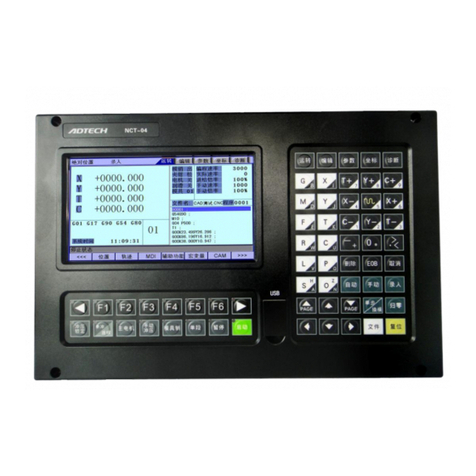
Adtech CNC9 Series User manual

ADTECH 9 Series
CNC Maintenance Manual

Basic Information
This Manual is written by Adtech (Shenzhen) Technology Co., Ltd.
This Manual is mainly written by Tang Xiaobing.
This Manual was first released on June 27, 2016 with version No. A0101 and item number is applicable for all
the CNC9 series.
This Manual was revised on November 23, 2017 by Xu Yuwen with version No. A0102 and item number is
applicable for all the CNC9 series.
This Manual was revised on February 1, 2018 by Xu Yuwen with version No. A0103 and item number is
applicable for all the CNC9 series.
This Manual was revised on July 21, 2018 by Tang Xiaobing and Yao Lei with version No. A0104 and item
number is applicable for all the CNC9 series.
Copyright
Adtech (Shenzhen) Technology Co., Ltd. (Adtech hereafter) is in possession of the copyright of this manual.
Without the permission of Adtech, the imitation, copy, transcription and translation by any organization or
individual are prohibited. This manual doesn’t contain any assurance, stance or implication in any form. Adtech
and the employees are not responsible for any direct or indirect data disclosure, profits loss or cause termination
caused by this manual or any information about mentioned products in this manual. In addition, the products and
data in this manual are subject to changes without prior notice.
All rights reserved.
Adtech (Shenzhen) Technology Co., Ltd.

ADTECH9 Series CNC Maintenance Manual
- 1 -
Precautions and Explanations
※Transport and storage:
)Do not stack product package more than six layers;
)Do not climb, stand on or place heavy stuff on the product package;
)Do not pull the cable still connecting with machine to move product.
)Forbid impact and scratch on the panel and display;
)Prevent the product package from humidity, sun exposure, and rain.
※Open-box inspection:
)Open the package to confirm the product to be purchased by you.
)Check damages situation after transportation;
)Confirm the integrity of parts comparing with the parts list or damages situation;
)Contact our company promptly for discrepant models, shortage accessories, or transport damages.
※Wiring
)Ensure the persons involved into wiring and inspecting are specialized staff;
)Guarantee the product is grounded with less than 4Ωgrounding resistance. Do not use neutral line (N)
to substitute earth wire.
)Ensure grounding to be correct and solid, in order to avoid product failures or unexpected
consequences;
)Connect the surge absorption diodes to the product in the required direction, otherwise, the product
will be damaged;
)Ensure the power switch is OFF before inserting or removing plug, or disassembling chassis.
※Overhauling
)Ensure the power is OFF before overhauling or components replacement;
)Make sure to check failures after short circuit or overloading, and then restart the machine after
troubleshooting
)Do not allow to frequently connect and disconnect the power, and at least one minute interval between
power-on and power-off.
※Miscellaneous
)Do not open housing without permission;
)Keep power OFF if not in use for a long time;
)Pay close attention to keep dust and ferrous powder away from control;
)Fix freewheel diode on relay coil in parallel if non-solid state relay is used as output relay.
)Check whether power supply meets the requirement to ensure not burning the control.

ADTECH9 Series CNC Maintenance Manual
- 2 -
)Install cooling fan if processing field is in high temperature, due to close relationship between service
life of the control and environmental temperature.
)Keep proper operative temperature range for the control: 0℃~ 60℃.
)Avoid using the product in the overheating, humid, dusty, or corrosive environments;
)Add rubber rails as cushion on the place with strong vibration.
※Maintenance
Please implement routine inspection and regular check upon the following items, under the general usage
conditions (i.e. environmental condition: daily average 30℃, load rate: 80%, and operating rate: 12 hours/ day)
Routine
Inspection
Routine
●Confirm environmental temperature, humidity, dust, or
foreign objects.
●Confirm abnormal vibration and noise;
Regular Check One year
●Check whether solid components are loose
●Confirm whether terminal block is damaged

Foreword
CNC9 series CNC system is an economic embedded CNC system developed by Adtech (Shenzhen) Technology
Co., Ltd. for lathe and milling machines and machining centers, where CNC9640 is four axes motion controller,
CNC9960 is six axes motion controller, CNC9650 and CNC9810 are five axes motion controllers, and
CNC9810E is bus motion controller. (Note: ETherCAT bus control can be configured at most 12 axes of thread.)
Instructions and reading convention of the Manual
Before using this CNC system, please read this Manual carefully to operate properly.
Terminology note and reading convention in this Manual:
CNC9640 is control systems with different axes and same hardware functions. The programs developed on this
platform contain M series software for milling machines and L series software for lathes. Different software has
different functions and masks.
M series are system for milling machine motion. The ‘M’ or “M series” mark indicates specific interface or
function for milling machine software system.
L series are system for lathe motion. The ‘L’ or “L series” mark indicates specific interface or function for lathe
software system.
“CNC system”, “NC controller” and “CNC9XXX” mentioned in this Manual all refer to
CNC9640/CNC9960/CNC9810/CNC9816;
The articles marked with “Caution” prompt users to pay special attention for operation or setting, or else this
operation may fail or certain action can’t be performed.

ADTECH9 Series CNC Maintenance Manual
- 1 -
Contents
1.System technical characteristics ......................................................................................- 7 -
1.1System technical parameters ...................................................................................................... - 7 -
1.2System operating condition ........................................................................................................ - 9 -
1.3System function.......................................................................................................................... - 9 -
1.3.1.Self-diagnosis function.................................................................................................................................... - 9 -
1.3.2.Compensation.................................................................................................................................................. - 9 -
1.3.3.Abundant instruction system ........................................................................................................................... - 9 -
1.3.4.Full Chinese menu operation & full screen edit ............................................................................................ - 10 -
1.3.5.Abundant error-correction functions ............................................................................................................. - 10 -
1.3.6.Program exchange between CNC system and PC ......................................................................................... - 10 -
2.Operating panel............................................................................................................... - 11 -
2.1ADTCNC96 series system LCD/keypad...................................................................................- 11 -
2.2ADTCNC99 and 98 series system LCD/keypad ...................................................................... - 13 -
2.3System menus........................................................................................................................... - 15 -
2.3.1.Autorun ......................................................................................................................................................... - 15 -
2.3.2.Program edit.................................................................................................................................................. - 16 -
2.3.3.Parameter ...................................................................................................................................................... - 16 -
2.3.4.Work coordinates........................................................................................................................................... - 17 -
2.3.5.Diagnosis....................................................................................................................................................... - 18 -
2.4Operating keys.......................................................................................................................... - 19 -
3.Manual operation............................................................................................................- 21 -
3.1Returning to reference point manually ..................................................................................... - 21 -
3.2Each axis returns to reference point separately ........................................................................ - 21 -
3.3Each axis return to reference point simultaneously.................................................................. - 21 -
3.4Reset machine tool position ..................................................................................................... - 21 -
3.5Reset relative position manually .............................................................................................. - 22 -
3.6Continuous feeding manually................................................................................................... - 22 -
3.7Single-step feeding ................................................................................................................... - 23 -
3.7.1Single-step increment selection...................................................................................................................... - 23 -
3.8Handwheel feeding................................................................................................................... - 24 -
3.9Manual auxiliary function operation ........................................................................................ - 25 -
3.10Tool setting............................................................................................................................... - 26 -

ADTECH9 Series CNC Maintenance Manual
- 2 -
3.10.1.Centered (M series) ..................................................................................................................................... - 26 -
3.10.2.Tool regulator (M series) ............................................................................................................................. - 28 -
3.10.3.Auto tool setting mode ................................................................................................................................ - 34 -
3.10.4.Four-point centering:................................................................................................................................... - 34 -
3.10.5.Calculate the center of the circle using two points and radius..................................................................... - 34 -
3.10.6.Calculate circle center using 3 points .......................................................................................................... - 35 -
3.11Manual operation...................................................................................................................... - 35 -
3.12Data recording .......................................................................................................................... - 35 -
3.13Update the coordinate system................................................................................................... - 35 -
3.14Coordinate Parameter ............................................................................................................... - 35 -
3.14.1.EXT offset coordinates................................................................................................................................ - 35 -
3.14.2.Tool Regulator Parameter............................................................................................................................ - 37 -
3.14.3.Tool setting by test cutting (L series)........................................................................................................... - 38 -
3.15Data settings ............................................................................................................................. - 38 -
3.15.1.Tool compensation data settings.................................................................................................................. - 38 -
3.15.2.System parameters setting ........................................................................................................................... - 39 -
3.16System shortcuts....................................................................................................................... - 39 -
4.Automatic Operation ...................................................................................................... - 41 -
4.1Memory operation .................................................................................................................... - 41 -
4.2MDI operation .......................................................................................................................... - 41 -
4.3USB disk DNC ......................................................................................................................... - 41 -
4.4Speed rate adjustment............................................................................................................... - 42 -
4.5SBK function............................................................................................................................ - 42 -
4.6BDT function............................................................................................................................ - 43 -
4.7Stopping automatic operating................................................................................................... - 43 -
5.Safe operation.................................................................................................................. - 44 -
5.1Emergency stop ........................................................................................................................ - 44 -
5.2Hard limit over travel ............................................................................................................... - 44 -
5.3Soft limit over travel................................................................................................................. - 44 -
6.Alarm and self-diagnosis function.................................................................................- 45 -
6.1NC program execution alarm error........................................................................................... - 45 -
6.2System environment alarm content codes ................................................................................ - 47 -
6.3Alarm processing...................................................................................................................... - 52 -

ADTECH9 Series CNC Maintenance Manual
- 3 -
6.4Self-diagnosis function............................................................................................................. - 52 -
7.Program saving & editing...............................................................................................- 53 -
7.1Saving the program in the memory .......................................................................................... - 53 -
7.1.1Keypad input (new program).......................................................................................................................... - 53 -
7.1.2Computer network access/serial port input..................................................................................................... - 53 -
7.1.3Copying processing files from USB disk ....................................................................................................... - 57 -
7.2Reading programs into work area............................................................................................. - 57 -
7.2.1Reading programs from controller into work area.......................................................................................... - 57 -
7.2.2Reading programs from USB disk into work area.......................................................................................... - 57 -
7.3Editing & modifying programs ................................................................................................ - 58 -
7.3.1Single-line copy, paste and delete................................................................................................................... - 58 -
7.3.2Multi-line copy, paste and delete.................................................................................................................... - 58 -
7.3.3Macro function fast programming.................................................................................................................. - 58 -
7.4Deleting files ............................................................................................................................ - 59 -
7.4.1Deleting files in memory ................................................................................................................................ - 59 -
8.Main interfaces of the system......................................................................................... - 60 -
8.1Position Interface...................................................................................................................... - 60 -
8.1.1Absolute Position ........................................................................................................................................... - 61 -
8.1.2Relative Position ............................................................................................................................................ - 62 -
8.1.3Comprehensive coordinates............................................................................................................................ - 63 -
8.1.4Deviation position .......................................................................................................................................... - 63 -
8.2Edit ........................................................................................................................................... - 64 -
8.2.1Program edit................................................................................................................................................... - 65 -
8.2.2New program.................................................................................................................................................. - 65 -
8.2.3Save as............................................................................................................................................................ - 65 -
8.3MDI interface ........................................................................................................................... - 65 -
8.4File management ...................................................................................................................... - 67 -
8.4.1Copy............................................................................................................................................................... - 67 -
8.4.2Paste ............................................................................................................................................................... - 68 -
8.4.3Cut.................................................................................................................................................................. - 68 -
8.4.4Connect computer .......................................................................................................................................... - 68 -
8.5Graphic Simulation................................................................................................................... - 68 -
8.6Parameter Interface................................................................................................................... - 69 -

ADTECH9 Series CNC Maintenance Manual
- 4 -
8.6.1Comprehensive Parameter.............................................................................................................................. - 71 -
8.6.2Axis parameters.............................................................................................................................................. - 72 -
8.6.3Management Parameter.................................................................................................................................. - 73 -
8.6.4Tool magazine parameters.............................................................................................................................. - 74 -
8.6.5Spindle parameters ......................................................................................................................................... - 74 -
8.6.6IO configuration parameters........................................................................................................................... - 75 -
8.7Compensation interface............................................................................................................ - 75 -
8.8Milling system workpiece coordinate system setting interface................................................ - 76 -
8.8.1Workpiece coordinate system......................................................................................................................... - 76 -
8.8.2Settings of tool setting parameter ................................................................................................................... - 78 -
8.8.3Allowance ...................................................................................................................................................... - 79 -
8.8.4Offset.............................................................................................................................................................. - 80 -
8.8.5Screw itch error compensation ....................................................................................................................... - 80 -
8.9Controller diagnosis interface (diagnosis)................................................................................ - 82 -
8.9.1Alarm check ................................................................................................................................................... - 82 -
8.9.2IO diagnosis interface..................................................................................................................................... - 82 -
8.9.3Function test................................................................................................................................................... - 82 -
8.9.4System Info .................................................................................................................................................... - 83 -
8.10Macro variable view interface (macro variable)....................................................................... - 83 -
8.11Current mode instruction info .................................................................................................. - 84 -
9.System maintenance........................................................................................................- 85 -
9.1Restart....................................................................................................................................... - 85 -
9.2System upgrade ........................................................................................................................ - 85 -
9.3Reset......................................................................................................................................... - 85 -
9.4Parameter backup and restore................................................................................................... - 85 -
9.5Enter BIOS ............................................................................................................................... - 86 -
10.System parameters.......................................................................................................... - 87 -
10.1Parameter index list.................................................................................................................. - 88 -
10.2Comprehensive parameter (P1.) ..............................................................................................- 111 -
10.3Axis parameter configuration (P2.) ........................................................................................ - 131 -
10.4Management parameter (P3.) ................................................................................................. - 158 -
10.5Tool magazine parameter (P4.)............................................................................................... - 168 -
10.6Spindle parameters (P5.) ........................................................................................................ - 168 -

ADTECH9 Series CNC Maintenance Manual
- 5 -
10.7Port configuration (P6.).......................................................................................................... - 178 -
11.Hardware interface definition and connection instructions...................................... - 182 -
11.1Installation Layout.................................................................................................................. - 182 -
11.1.1.9640 series external interface diagram ...................................................................................................... - 182 -
11.1.2.9810 and 9650 series external interface diagram....................................................................................... - 183 -
11.1.3.99 series external interface diagram .......................................................................................................... - 184 -
11.1.4.96 Series Mounting dimensions................................................................................................................. - 185 -
11.1.5.99 Series Mounting dimensions................................................................................................................. - 185 -
11.1.6.Installation precautions.............................................................................................................................. - 186 -
11.2Interface Definition ................................................................................................................ - 188 -
12.2.1.Motor driver control interface ................................................................................................................... - 188 -
12.2.2.Digital input interface................................................................................................................................ - 192 -
12.2.3.Digital output interface.............................................................................................................................. - 198 -
12.2.4.Handheld box interface ............................................................................................................................. - 202 -
12.2.5.Analog output interface (9640 series XS8)................................................................................................ - 205 -
12.2.6.Spindle encoder interface (9640 series XS12)........................................................................................... - 206 -
12.2.7.RS232 interface (96 series XS9, 99 series XS11), RS-485 interface (9810 9650) and RJ45 network interface
(9 series) - 209 -
12.2.8.USB memory connection interface (96 series XS10) ................................................................................ - 210 -
12.2.9.PC USB communication interface (96 series XS11, 99 series X13).......................................................... - 210 -
11.3Electrical connection diagram ................................................................................................ - 210 -
11.3.1.Symbol schematic diagram........................................................................................................................ - 210 -
11.3.2.Power connection diagram ........................................................................................................................ - 211 -
11.3.3.Servo driver connection diagram............................................................................................................... - 212 -
11.3.4.Step connection diagram ........................................................................................................................... - 213 -
11.3.5.IO electrical connection diagram............................................................................................................... - 214 -
11.3.6.ADT9163 splitter wiring diagram.............................................................................................................. - 217 -
11.3.7.ET102A splitter wiring diagram ................................................................................................................ - 220 -
11.3.8.ET202A splitter wiring diagram ................................................................................................................ - 223 -
11.3.9.ADT-I24HNA input board......................................................................................................................... - 224 -
11.3.10.ADT-O24HNA output board ................................................................................................................... - 225 -
12.CNC9 Series Hardware Interface Instructions ..........................................................- 227 -
12.1.External Interface Diagram .......................................................................................................................... - 227 -

ADTECH9 Series CNC Maintenance Manual
- 6 -
12.2.Motor driver control interface ...................................................................................................................... - 227 -
12.3.ADT9163 splitter wiring diagram ................................................................................................................ - 230 -
12.4.ET102A splitter wiring diagram................................................................................................................... - 232 -
12.5.ET202A splitter wiring diagram................................................................................................................... - 236 -
13.Transmission of Computer NC Program Network to the system.............................- 239 -
13.1.System IP Settings........................................................................................................................................ - 239 -
14.Appendix-Common Servo Wiring Diagrams.............................................................. - 243 -
14.1.Pulse control port wiring definition.............................................................................................................. - 243 -
14.1.1.Wiring diagram of ADTECH QS, QX and Shanyang servo driver............................................................ - 243 -
14.1.2.Yaskawa, Matsushita, Fuji, TECO............................................................................................................. - 243 -

ADTECH9 Series CNC Maintenance Manual
- 7 -
1. System technical characteristics
1.1 System technical parameters
Function Name Specification
Control axis
Control axes
4 axes (CNC9640 series)
5 axes (CNC9650 series)
5 axes (CNC9810 series)
6 axes (CNC9960 series)
Bus axes (CNC9810E) up to 12 axes
Simultaneous control axes
4 axes linear interpolation (CNC9640 series)
6 axes linear interpolation (CNC9960 series)
5 axes linear interpolation (CNC9810 series)
5 axes linear interpolation (CNC9650 series)
2 axes arc interpolation
Input instruction
Minimum setting unit 0.001 mm
Minimum moving unit 0.001 mm
Maximum instruction value ±9999.999 mm
Feeding
Fast feeding speed
X axis, Y axis, Z axis, A axis: 9999 mm/min
(maximum)
Feeding speed range
Per minute 1~9999 mm/min
Per rotation 1~500 rpm
Automatic acceleration/deceleration Yes
Feeding speed rate 10~150%
Manual
Continuous manual feeding, Yes
Returning to reference point manually
All control axes return to reference point
simultaneously
(allow setting order of priority)
Single-step/handwheel function Yes
Interpolation
Positioning, linear interpolation, arc
interpolation
G00,G01,G02/G03

ADTECH9 Series CNC Maintenance Manual
- 8 -
Function Name Specification
Operating mode MDI, auto, manual, single-step, edit Yes
Testing function
Test run, single program segment,
Handwheel
Yes
Coordinate system and
pause
Pause (sec/ms) G04 X/P_
Coordinate system setting
G92 (M series)
G50 (L series)
Automatic coordinate system setting Yes
Safe functions
Soft & hard limit check Yes
Emergency stop Yes
Program storage
Program storage capacity, storage
quantity
Capacity: 2G
100 work areas
No limit on processing file quantity
Program edit
Program edit Insert, modify, delete, cancel
Program No., sequence No., address,
character retrieval
Yes
Decimal point programming Yes
Display
800×480 pixels 7” LCD
800×600 pixels 8”, 10.4” LCD
CNC9640, 9650
CNC9810, 9960
Position screen, program edit
Tool compensation setting, alarm
display
Handwheel test, diagnosis screen
Parameter setting, graphic simulation
Yes
M, S, T function
Auxiliary function M code
Spindle function
S0-S15 (gear control)
S15-S99999 (analog)
Tool function T code
Compensation function Tool compensation memory 30 tools length, radius compensation

ADTECH9 Series CNC Maintenance Manual
- 9 -
Function Name Specification
Reverse clearance compensation Yes
Other functions
Measurement centered
Automatic tool regulator
Yes
Specify arc radius R/center position Yes
Electronic gear ratio Yes
1.2 System operating condition
Operating voltage 24V DC (with filter)
Operating temperature 0℃-45℃
Optimum operating temperature 5℃-40℃
Operating humidity 10%-90% (no condensing)
Optimum operating humidity 20%-85%
Storage temperature 0℃-50℃
Storage humidity 10%-90%
Operating environment
No excessive dust, acid, alkali, corrosive and explosive gases, no strong
electromagnetic interference
1.3 System function
1.3.1. Self-diagnosis function
Diagnose CPU, memory, LCD, I/O interface, parameter state, coordinates and processing program
comprehensively every time the system is started or reset; diagnose power supply, spindle, limit and I/O ports in
real-time during operating.
1.3.2. Compensation
Automatic reverse clearance compensation
Automatic tool length compensation
Automatic tool radius compensation
Automatic tool radius biasing and automatic tool tip transition
1.3.3. Abundant instruction system
Scaling instruction
Mirror processing instruction
Tool biasing instructions

ADTECH9 Series CNC Maintenance Manual
- 10 -
Program cycle, program skip, program shift, program transfer, different end processing modes, macro definition
and program management instructions
Fixed-point instructions: starting point, setting point, etc.
Linear, arc and spiral interpolation instructions
Six workpiece coordinate systems, nine extension coordinate systems and one reference point
1.3.4. Full Chinese menu operation & full screen edit
9640/9620 CNC system uses cascading menu structure and full Chinese operation to ensure simple, intuitive and
convenient operation.
1.3.5. Abundant error-correction functions
Point out the nature and correct the errors in operation.
1.3.6. Program exchange between CNC system and PC
Perform CAD/CAM/CAPP auxiliary programming with abundant software in PC, and then transmit CNC
program to the system through communication interface (USB disk, RS232 interface), or transmit the programs
from the system to PC.

ADTECH9 Series CNC Maintenance Manual
- 11 -
2. Operating panel
2.1 ADTCNC96 series system LCD/keypad
Keypad
Fig. 2.1 CNC9640 Operating Panel Diagram
Note:
Press the submenu buttons to perform the operations of submenus.
Manual axis moving and edit & input are composite. It has different definitions in different modes.
System working mode switch area is used to switch working modes, which can improve the security and system
performance. Handwheel and single-step mode are switched with Repeat button.

ADTECH9 Series CNC Maintenance Manual
- 12 -
LCD unit
Fig. 2.2 CNC9640 LCD Screen Diagram
Note:
Screen info shows the information of current window
Working mode info shows currently selected working mode
System main screen shows current main screen.
The submenu options are used to switch submenus with left triangle, F1~F6 and right triangle. The right arrow is
used to turn pages, and the left arrow is used to close the submenus in next level and previous menu.

ADTECH9 Series CNC Maintenance Manual
- 13 -
2.2 ADTCNC99 and 98 series system LCD/keypad

ADTECH9 Series CNC Maintenance Manual
- 14 -

ADTECH9 Series CNC Maintenance Manual
- 15 -
2.3 System menus
CNC96XX system uses cascading menu structure. You can press the following keys to operate the menus.
Press a key to show the corresponding content in the bottom of the LCD.
Key in the left: Return to previous menu
Key in the right: Turn pages to show other menus of same level
The main menus of the system include [Monitor], [Prog Edit], [Parameter], [Coordinate] and [Diagnosis]. Each
main menu contains several submenus, which are shown below:
2.3.1. Autorun
This manual suits for next models
6
Table of contents
Other Adtech Control System manuals

Adtech
Adtech Q2BYG806DK User manual
Adtech
Adtech ADT-DK300A User manual

Adtech
Adtech ADT-RC400 User manual
Adtech
Adtech ZM430A-A01 User manual
Adtech
Adtech TV5600-B01 Series User manual

Adtech
Adtech ADT-CNC4220 User manual
Adtech
Adtech ADT-09 Series User manual
Adtech
Adtech 4 Series Mounting instructions

Adtech
Adtech 4 Series User manual
Adtech
Adtech ADTECH4 CNC Series User manual
