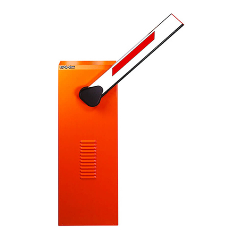
FAAC B614 User manual

B614

FAAC S.p.A. Soc. Unipersonale
Via Calari, 10 - 40069 Zola Predosa BOLOGNA - ITALY
Tel. +39 051 61724 - Fax +39 051 09 57 820
www.faac.it - www.faacgroup.com
FAAC International Inc.
Headquarter & East Coast Operations
3160 Murrell Road
Rockledge, FL 32955
Tel. 800 221 8278
www.faacusa.com
FAAC International Inc.
West Coast Operations
357 South Acacia Avenue
Fullerton, CA 92831

B614 1 532297 - Rev.D
CONTENTS
1. IMPORTANT SAFETY INFORMATION .................. 3
UL325 Gate Operator Classifications..................... 5
Introduction to this instructions manual................. 6
Transport and storage .................................. 7
Unpacking and handling................................ 8
Disposal of the product................................. 8
2. B614 .................................................. 9
2.1 Intended use......................................... 9
2.2 Limitations of use .................................... 9
2.3 Unauthorised use .................................... 9
2.4 Emergency use...................................... 10
2.5 Manual operation ................................... 10
Release procedure .................................... 10
Restore normal operation ............................. 10
2.6 Product identification................................ 11
2.7 Technical specifications .............................. 11
2.8 Component identification ............................ 12
2.9 Installation components ............................. 13
2.10 Optional accessories................................ 13
3. INSTALLATION REQUIREMENTS...................... 14
3.1 Mechanical requirements ............................ 14
3.2 Electrical system .................................... 15
3.3 Example system..................................... 16
4. MECHANICAL INSTALLATION......................... 17
4.1 Tools required ....................................... 17
4.2 Installing the foundation plate ....................... 18
4.3 Installing the barrier body ........................... 19
Rounting the cables inside the barrier .................. 20
4.4 Installing the arm ................................... 21
Preparing the rocker arm .............................. 21
Installation ........................................... 21
4.5 Mounting the spring................................. 23
Turnbuckle ........................................... 23
Single spring.......................................... 24
Double spring......................................... 24
4.6 Accessories on the arm............................... 25
4.7 Balancing the arm................................... 25
4.8 Limits adjustment................................... 26
4.9 Grounding the door ................................. 27
4.10 Closing the door ................................... 27
4.11 Installing the top cover ............................. 28
5. ELECTRONIC INSTALLATION.......................... 29
5.1 Board E614 ......................................... 29
Components ......................................... 29
5.2 Connections ........................................ 31
Control devices ....................................... 31
External loops ........................................ 32
BUS devices........................................... 32
OUT outputs .......................................... 32
24 V "flashing light ................................. 32
Motor ................................................ 32
Encoder .............................................. 32
Arm lights ............................................ 33
Integrated flashing light............................... 33
XF radio module ...................................... 33
Mains supply and earthing............................. 33
6. START-UP ............................................ 34
6.1 Programming ....................................... 34
Basic programming ................................... 34
Advanced programming .............................. 35
6.2 Operating logics..................................... 38
EP - Semi-automatic step by step ..................... 38
A- Automatic......................................... 38
AP - Automatic step-by-step.......................... 38
b- Semi-automatic b ................................. 38
bC- Semiautomatic bon opening/ person present Con
closing ............................................... 38
C- Dead-man ........................................ 38
P- Parking ........................................... 38
PA - Parking Automatic ............................... 38
6.3 SET-UP ............................................. 39
7. PUTTING INTO SERVICE .............................. 40
7.1 Final checks......................................... 40
7.2 Final operations ..................................... 40
Field installed labels .................................. 40
8. ACCESSORIES......................................... 41
8.1 24V
"flashing light ................................ 41
8.2 XF radio module..................................... 41
Deleting radio controls from memory .................. 42
LC/RC - Remote code STORING procedure ............... 42
8.3 BUS 2easy devices................................... 43
Connection ........................................... 43
BUS 2easy photocells .................................. 43
Control devices ....................................... 43
BUS 2easy device registration.......................... 44
8.4 Rectangular arm light kit ............................ 45
8.5 Integrated flashing light ............................. 45
8.6 Articulated arm kit .................................. 45
8.7 Skirt................................................ 46

B614 2 532297 - Rev.D
ADDENDUM
1 Foundation (barrier in maximum configuration) ......55
2 Balancing system...................................56
3 Routine maintenance ...............................57
TABLES
1 Symbols: notes and warnings on the instructions ......6
2 Symbols: markings on packaging .....................7
3 Technical data......................................11
4 E614 board technical data...........................29
5 Basic programming.................................35
7 Advanced programming ............................36
6 Default speed ......................................36
8 Orienting the photocells ............................43
9 Addressing control devices ..........................44
10 Troubleshooting....................................52
11 Rectangular arm balancing..........................56
8.8 Foot................................................ 46
8.9 Fork ................................................ 46
9. MASTER-SLAVE....................................... 47
Connection ........................................... 47
Slave barrier configuration ............................ 48
10. DIAGNOSTICS ....................................... 49
10.1 LEDs check......................................... 49
10.2 Direction of movement check ....................... 49
10.3 Encoder operation check............................ 49
10.4 Automation system status check .................... 49
10.5 Check firmware version............................. 49
10.6 Check of the registered BUS 2easy devices............ 49
11. MAINTENANCE...................................... 50
11.1 Routine maintenance............................... 50
11.2 Replacing the spring and flanged bushing ........... 51
11.3 Replacing the gearmotor ........................... 51
11.4 Fuse replacement .................................. 52
11.5 Operational problems .............................. 52
12. INSTRUCTIONS FOR USE ............................ 53
12.1 Safety recommendations ........................... 53
12.2 Emergency use..................................... 53
12.3 Manual operation .................................. 53
Release procedure .................................... 54
Restore normal operation ............................. 54

B614 3 532297 - Rev.D
Important Installation Instructions
1. Install the gate operator only when the
following conditions have been met:
• The operator is appropriate for the type
and usage class of the gate.
• All openings of a horizontal slide gate
have been guarded or screened from
the bottom of the gate to a minimum
of 4 feet (1.25 m) above the ground to
prevent a 2.25 inch (55 mm) diameter
sphere from passing through openings
anywhere in the gate or through that
portion of the adjacent fence that the
gate covers when in the open position.
• All exposed pinch points are eliminated
or guarded.
• Guarding is supplied for exposed rollers.
2. The operator is intended for installation on
gates used by vehicles only. Pedestrians
must be provided with a separate access
opening.
3. To reduce the risk of entrapment when
opening and closing, the gate must be
installed in a location that allows adequate
clearance between the gate and adjacent
structures. Swinging gates shall not open
outward into public access areas.
4. Before installing the gate operator, ensure
that the gate has been properly installed
and that it swings freely in both directions.
Do not over-tighten the operator clutch or
pressure relief valve to compensate for a
damaged gate.
5. User controls must be installed at least 6
feet (1.83 m) away from any moving part
of the gate and located where the user
is prevented from reaching over, under,
around or through the gate to operate the
controls. Controls located outdoors or those
that are easily accessible shall have security
features to prevent unauthorized use.
1. IMPORTANT SAFETY INFORMATION
Important Safety Instructions
WARNING - TO REDUCE THE RISK OF SEVERE
INJURY OR DEATH:
• READ AND FOLLOW ALL INSTRUCTIONS.
• Never let children operate or play with the
gate controls. Keep remote controls away
from children.
• Always keep people and objects away
from the gate. NO ONE SHOULD CROSS
THE PATH OF A MOVING GATE.
• Test the gate operator monthly. The gate
MUST reverse on contact with a rigid
object or when an object activates a non-
contact sensor. If necessary, adjust the
force or the limit of travel and then retest
the gate operator. Failure to properly
adjust and retest the gate operator can
increase the risk of injury or death.
• Use the manual release mechanism only
when the gate is not moving.
• KEEP GATE PROPERLY MAINTAINED. Have
a qualied service person make repairs to
gate hardware.
• The entrance is for vehicles only.
Pedestrians must use a separate entrance.
• SAVE THESE INSTRUCTIONS.

B614 4 532297 - Rev.D
6. The Stop and/or Reset buttons must be located
within line-of-sight of the gate. Activation of
the reset control shall not cause the operator to
start.
7. All warning signs and placards must be
installed and easily seen within visible
proximity of the gate. A minimum of one
warning sign shall be installed on each side of
the gate.
8. For gate operators that utilize a non-contact
sensor (photo arm or the like):
• See instructions on the placement of
non-contact sensors for each type of appli-
cation.
• Exercise care to reduce the risk of nuisance
tripping, such as when a vehicle trips the
sensor while the gate is still moving.
• Locate one or more non-contact sensors
where the risk of entrapment or obstruction
exists, such as at the reachable perimeter of
a moving gate or barrier.
9. For gate operators that utilize a contact sensor
(edge sensor or similar):
• Locate one or more contact sensors where
the risk of entrapment or obstruction exists,
such as at the leading edge, trailing edge,
and post mounted both inside and outside
of a vehicular horizontal slide gate
• Locate one or more contact sensors at the
bottom edge of a vehicular vertical lift gate.
• Locate one or more contact sensors at the
bottom edge of a vertical barrier (arm).
• Locate one or more contact sensors at the
pinch point of a vehicular vertical pivot gate.
• Locate hard-wired contact sensors and
wiring so that communication between
sensor and gate operator is not subjected to
mechanical damage.
• Locate wireless contact sensors, such as
those that transmit radio frequency (RF)
signals, where the transmission of signals
are not obstructed or impeded by building
structures, natural landscaping or similar
General Safety Precautions
Installation
• If you have any questions or concerns
regarding the safety of the gate operating
system, do not install the operator and
consult the manufacturer.
• The condition of the gate structure itself
directly aects the reliability and safety of
the gate operator.
• Only qualied personnel should install
this equipment. Failure to meet this
requirement could cause severe injury
and/or death, for which the manufacturer
cannot be held responsible.
• Install devices such as reversing edges
and photo arms to provide better
protection for personal property and
pedestrians. Install reversing devices that
are appropriate to the gate design and
application.
• Before applying electrical power,
ensure that voltage requirements of the
equipment correspond to the supply
voltage. Refer to the label on your gate
operator system.
Usage
• Use this equipment only in the capacity
for which it was designed. Any use other
than that stated should be considered
improper and therefore dangerous.
• The manufacturer cannot be held
responsible for damage caused by
improper, erroneous or unreasonable use.
• If a gate system component malfunctions,
disconnect the main power before
attempting to repair it.
hindrances. Wireless contact sensors shall
function under their intended end-use
conditions.

B614 5 532297 - Rev.D
• Do not impede the movement of the gate,
you may injure yourself or damage the gate
system as a result.
• This equipment may reach high thermal
temperatures during normal operation,
therefore use caution when touching the
external housing of the gate operator.
• Use the manual release mechanism according
to the procedures presented in this manual.
• Before performing any cleaning or
maintenance operations, disconnect power
to the equipment.
• All cleaning, maintenance or repair work
must performed by qualied personnel.
UL325 GATE OPERATOR CLASSIFICATIONS
RESIDENTIAL VEHICULAR GATE OPERATOR
CLASS I
A vehicular gate operator system intended
for use in a single family dwelling, garage or
associated parking area.
COMMERCIAL / GENERAL ACCESS VEHICULAR GATE
OPERATOR CLASS II
A vehicular gate operator system intended for
use in commercial locations or buildings such
as multi-family housing units (ve or more
single family units), hotels, parking garages,
retail stores or other buildings that service the
general public.
INDUSTRIAL / LIMITED ACCESS VEHICULAR GATE
OPERATOR CLASS III
A vehicular gate operator system intended for
use in industrial locations or buildings such as
factories, loading docks or other locations not
intended to service the general public.
RESTRICTED ACCESS VEHICULAR GATE OPERATOR
CLASS IV
A vehicular gate operator system intended for
use in guarded industrial locations or buildings
such as airport security areas or other restricted
access locations that do not service the general
public, and in which unauthorized access is pre-
vented via supervision by security personnel.

B614 6 532297 - Rev.D
INTRODUCTION TO THIS INSTRUCTIONS MANUAL
Meaning of the symbols used
1 Symbols: notes and warnings on the in-
structions
FWARNING ELECTRIC SHOCK HAZARD -The operation
or stage described must be performed following the
instructions supplied and applicable safety regulations
!
WARNING, PERSONAL INJURY HAZARD OR RISK OF
DAMAGE TO COMPONENTS - The operation or stage
described must be performed following the supplied
instructions and applicable safety regulations
WARNING - Details and specifications that must be
complied with in order to ensure that the system
operates correctly.
RECYCLING and DISPOSAL - Components and struc-
tural materials, batteries and electronic components
must not be disposed of together with household
waste.They must be taken to authorised disposal and
recycling centres
For manual lifting, there should be 1 person for every
20 kg to be lifted
PAGE E.g.: 6 see Page 6
FIGURE E.g.: 1-3 see Figure 1 - item 3
TABLE E.g.: 1 see Table 1
§ CHAPTER/SECTION E.g.: §1.1 see section 1.1
APPENDIX E.g.: 1 see Appendix 1
Automatic operation - automation locked
Manual operation - automation unlocked

B614 7 532297 - Rev.D
TRANSPORT AND STORAGE
! Follow the instructions on the packaging during
handling. Two people must move the package. Use
the HANDLES.
2 Symbols: markings on packaging
Read the instructions
This way up indication: do not turn upside down
Store away from water and humidity
Maximum number of stackable pallets
3Maximum number of stackable packages
Percent storage humidity
Storage temperature
CE marking
Wear work gloves
Wear safety footwear
20 kg is the MAX weight one person can lift
Kg ___
_
Weight of package
PALLETISED SUPPLY
SINGLE PACKAGE
! Use a forklift or pallet truck, fol-
lowing safety regulations to avoid
the risk of impacts or collisions.
For manual lifting, there should
be 1 person for every 44 lb (20 kg)
to be lifted.
STORAGE
Store the product in its original packaging, in closed
and dry premises, protected from the sun and free
from dust and aggressive substances. Protect from
mechanical stress. If stored for more than 3 months,
regularly check the condition of the components and
the packaging.
-Storage temperature: 41° to 86°F (5° to 30°C).
-Percentage of humidity: 30% to 70%.

1
B614 8 532297 - Rev.D
1
2
3
4
HAZARDOUSVOLTAGE.
Disconnectpower
beforeservicing.
WARNING
VOLTAGEDANGEREUSE.
Débrancherl’alimentation
avantl’entretien.
ATTENTION
WARNING
Movinggatecancause
SeriousInjuryorDeath
KEEPCLEAR!Gatemaymoveat any
timewithoutpriorwarning.
Donotletchildrenoperatethe gate or
playinthegatearea.
Thisentranceisforvehiclesonly.
Pedestriansmustuseseparate
entrance.
ATTENT ION
Unebarrièreenmouvementpeut
causerdesblessuresgravesoude
mortalité
RESTEZÀL’ÈCARTE!Labarrière peut
bougerátoutmomentetsans
avertissement.Nelaissezpaslesenfants
utiliserlabarrièreoujouerdans la région
delabarrière.L’entréeestpourvéhicules
seulement.Lespiétonsdoiventutiliser
unentréeséparée.
HAZARDOUSVOLTAGE.
Disconnectpower
beforeservicing.
WARNING
VOLTAGEDANGEREUSE.
Débrancherl’alimentation
avantl’entretien.
ATTENTION
Movinggate can cause
SeriousInjur y or Death
KEEPCLEAR! Gate may move at any
timewithout prior warning.
Donot let children operate the gate or
playin the gate area.
Thisentrance is for vehicles only.
Pedestriansmust use separate
entrance.
WARNIN G ATTENTION
Unebarrière en mouvement peut
causerdes blessures graves ou de
mortalité
RESTEZÀ L’ÈCARTE ! La barrière peut
bougerá tout moment et sans
avertissement.Ne laissez pas les enfants
utiliserla barrière ou jouer dans la région
dela barrière. L’entréeest pour véhicules
seulement.Les piétons doivent utiliser
unentrée séparée.
5
UNPACKING AND HANDLING
Two people are reccomended to handle the packa-
ge. Use the handles.
!Never manage the barrier by holding the control
board.
1. Carefully set the package down on the ground.
2. Cut the packaging to open it right up and remove
all the packaging material.
3. Stand the barrier on the base.
Check that all components are present and intact
1.
4. Dispose of the packaging materials.
!The packaging materials (plastic, polystyrene etc.)
must not be left within reach of children as they are
potential sources of danger.
When you have finished with them, dispose of the
packaging in the appropriate containers, as per
applicable waste disposal regulations.
1B614 barrier body
2Top cover
3Installation accessories
4Instruction manual
5UL Field Labels
DISPOSAL OF THE PRODUCT
After having dismantled the product, dispose of it
in compliance with the current waste disposal regu-
lations.
Components and structural materials, batteries and
electronic components must not be disposed of
together with household waste. They must be taken
to authorised disposal and recycling centres.

B614 9 532297 - Rev.D
2. B614
2.1 INTENDED USE
The B614 barriers are designed for vehicular access
control in residential buildings/apartment complexes.
To move the arm manually, follow the instructions for
manual operation.
! Any other use that is not expressly specified in these
instructions is prohibited and could affect the integri-
ty of the product and/or represent a source of danger.
2.2 LIMITATIONS OF USE
Comply with the limitations on frequency of use listed
in the technical data section.
The B614 requires the use of a specific FAAC arm
that conforms to the dimensions indicated in this
manual. Only the FAAC accessories indicated in this
manual should be installed on the arm.
The B614 requires the use of a FAAC spring that is
adequate for counterbalancing the weight of the arm
and the relative accessories.
Barriers must be used exclusively for vehicle access
control and it must be complemented by suitable
visible signs prohibiting foot traffic. A separate route
for foot traffic outside the range of the arm must be
provided and properly indicated.
The presence of weather conditions such as snow, ice
and strong wind, even occasional, could affect the
correct operation of the automation, the integrity of
the components and be a potential source of danger
(see § 2.4). The limitations of use of the B614 in wind
is equivalent to grade 10 on the Beaufort Scale (max.
speed: 63 mph).
The installation must be visible during the day and
at night. If it is not, appropriate solutions must be
provided to make the fixed and moving parts visible
(light kit on the arm).
The B614 must be connected to a FAAC electronic
board as indicated in this manual (Technical cha-
racteristics).
Implementing the automation requires the installa-
tion of the necessary safety devices, identified by the
installer through an appropriate risk assessment of
the installation site.
2.3 UNAUTHORISED USE
-Uses other than the intended ones are prohibited.
-It is prohibited to install the automation system
outside of the limits specified in theTechnical Data
and Installation Requirements sections.
-It is forbidden to use B614 in a constructional
configuration other than the one provided by the
manufacturer.
-No component part of the product may be mo-
dified.
-It is prohibited to install the automation system
on escape routes.
-It is prohibited to install the automation system in
environments in which there is a risk of explosion
and/or fire: the presence of flammable gases or
fumes is a serious safety hazard.
-It is prohibited to power the system with energy
sources other than those specified.
-It is prohibited to integrate commercial systems
and/or equipment other than those specified, or
use them for purposes not intended and authorised
by their respective manufacturers.
-Do not expose the barrier to direct jets of water of
any type and size.
-Do not expose the barrier to aggressive chemical
or environmental agents.
-The barrier may not be used to move moving parts
other than the arms produced by FAAC specified
in this manual.
-Use to control pedestrian access, bicycle traffic and
the passage of animals is prohibited.
-Use of the barrier at level crossings is prohibited.
-Use of the barrier on public thoroughfares is
prohibited.
-It is prohibited to use and/or install accessories
which have not been specifically approved by
FAAC S.p.A.
-It is prohibited to use the automation system before
performing commissioning.
-It is prohibited to use the automation system in the
presence of faults which could compromise safety.
-It is prohibited to use the automation system with
the fixed and/or mobile guards removed or altered.
-Do not use the automation system unless the area
of operation is free of persons, animals or objects.
-Do not enter/remain in the area of operation of the
automation system while it is moving.
-Do not try to prevent the movement of the auto-
mation system.
-Do not climb or catch on to the arm or lift yourself
up on it. Do not climb on the barrier cabinet.
-Do not allow children to approach or play in the
area of operation of the automation system.
-Do not allow the control devices to be used by
anyone who is not specifically authorised and
trained to do so.
! During manual handling, accompany the arm slowly
for the entire movement. Do not let the arm travel
freely.

2
B614 10 532297 - Rev.D
1
2
2.4 EMERGENCY USE
In emergencies or if there is a fault, turn off the power
supply to the automation and disconnect the backup
batteries if there are any. If the arm can be moved
safely by hand, use the MANUAL OPERATION mode;
otherwise place the automation out of service until it
has been reset/repaired.
In the case of a breakdown, the automation must be
reset/repaired exclusively by the installer/maintenance
technician.
2.5 MANUAL OPERATION
!- Operate the manual release only when there is no
electrical power and the arm is not moving
- During manual handling, accompany the arm
slowly for the entire movement. Do not let the arm
travel freely.
- Do not leave the barrier unlocked. After the ma-
nual movement, restore automatic operation.
WARNING: The arm could come down unexpectedly
after being released. Always make sure that the
area underneath the arm is clear of objects or people
before operating the manual release key.
RELEASE PROCEDURE
1. 2 Open the lock cover. Insert the key and turn
it once counterclockwise until it stops (1).
2. Move the barrier arm manually.
3. Restore the operation.
RESTORE NORMAL OPERATION
1. 2 Insert the key and turn it twice clockwise
until it stops (2).
2. Check that manual movement is inhibited.
3. Remove the key and close the cover.

3
B614 11 532297 - Rev.D
tttttt
tttttt
tttt tttt
tttttt
tttt
tt
tttttt
tttttt
tttttt
BARRIER B614 110-120 VAC
FAAC International
xxxxxxxx xxxxxxxxxxx xxxxxxxxxxxx
xxxxxxxxx
0118 0001
Part Number
Product name
IDENTIFICATION NUMBER
Month/year of production +
progressive number for the
month of production
Example:
made in:
January 2019 progressive:
0001
2.6 PRODUCT IDENTIFICATION
The product is identified by the plate (3).
2.7 TECHNICAL SPECIFICATIONS
The B614 is an electromechanical barrier with a E614
electronic board built in. The B614 must be installed
on the specific foundation plate and set onto a plinth.
RH/LH barrier The B614 can be easily installed as a right
hand or left hand barrier without having to do any
major modification the its structure.
It's reccomended to install the barrier with the door
towards the inside of the property for easier access.
Thebarrierisdefined bylookingatitfromthedoor side:
- RH barrier (right): the arm closes towards the right
(in a clockwise direction)
- LH barrier (left): the arm closes towards the left (in
an counterclockwise direction)
Self-Locking gear reduction To allow manual operation,
use the provided release mechanism.
Encoder The B614 has a built in encoder. The encoder
constantly detects the precise position of the arm and
makes it possible to manage the end of movement and
slow downs stored with the set up.
Anticrushing operation The encoder allows the board to
implement an anticrushing feature:
-the detection of an obstacle during closing causes
the movement to be reversed
-the detection of an obstacle during opening causes
the arm to stop.
Adjustablepositive stop The barrier has built in adjustable
mechanical positive stops to set the end of opening
and closing movements.
Equipment A rectangular arm can be installed. The
components necessary for the installation and the op-
tional equipment are listed in the dedicated sections.
Balancingsystem One or two balancing springs must be
used to balance the arm. The use of single or double
springs depends on the length and configuration of
the installed arm.
!The balancing system is important for safety reasons
to ensure the stability and control of the arm during
movement and keep it operating properly over time.
Master-Slave Configuration The configuration of two bar-
riers that open in opposite directions can be achieved
with the Master-Slave configuration.
Power supply voltage 115V~ +/-10% 50/60 Hz
Electric motor 24 V
"
Max power 165 W
Max torque 220 lbf (300 Nm)
Opening time (80°)
- arm < 9.8 ft (3 m)
- arm > 9.8 ft (3 m)
less than 2 sec.
less than 3 sec.
Use frequency Continuous use
Ambient operating tem-
perature
-4 ° to +131 °F (-20 ° to +55 °C)
Protection rating IP 55 (control board) - IP 44
Dimensions (L x D x H) 9.75 x 14 x 45.75 in
(247 x 357 x 1163 mm)
Weight 88 lb (40 kg)
FAAC foundation plate
Dimensions (L x H) 9.05x12.01 in (230 x 305 mm)
FAAC arm Arm length
Rectangular arm 4.4 ... 12.5 ft (1.35 ... 3.81 m)
3 Technical data

4
B614 12 532297 - Rev.D
1
58
9
7
6
2
3
10
411
12
11
B614 door side
B614 arm side
2.8 COMPONENT IDENTIFICATION
Standard equipment on the barrier body (4):
1 Enclosure
2 Drive shaft
3 Manual release (triangular key)
4 Top cover
5 Door with lock
6 E614 control board
7 E614 control board cover
8 Rocker arm / upper spring mounting hole
9 Electromechanical gearmotor with Encoder
10 Lower spring mounting hole
11 Positive stops
12 Mains ON/OFF switch

5
B614 13 532297 - Rev.D
1
2
3
4
Foundation plate
Single spring Double spring
Rectangular arm
Bracketfor rectangulararm
2.9 INSTALLATION COMPONENTS
A typical installation includes the following FAAC
components supplied separately (5):
1 Foundation plate
2 Rectangular arm
3 Arm mounting bracket
4 Single or double balancing spring
2.10 OPTIONAL ACCESSORIES
For the FAAC accessories for the B614 see the chap-
ter § 8.

6
B614 14 532297 - Rev.D
33.8 in
(860 mm)
11.8 in
(300 mm)
14.2 in
(360 mm)
9 in
(230 mm) 12 in
(305 mm)
45.8 in
(1163 mm)
Before starting any work make sure that all the fol-
lowing conditions are present, to ensure a safe and
reliable installation of the B614 barrier operator.
!There is firm ground to support the weight of the
barrier with flat, horizontal paving. There must be no
chance of water accumulating in the installation area.
For the installation of detection loops, refer to the
specific instructions.
There is a safety area between the wall (or other fixed
element) and the end of the arm, to protect against
the risk of people becoming trapped/crushed.
There are safety areas between the fixed and moving
parts to prevent hands from being crushed.
There is enough working space for the installation
activities and subsequent maintenance operations,
bearing in mind the opening of the service door
and the positioning/removal of the cabinet and any
other elements.
There are no fixed or mobile obstacles to the move-
ment of the arm (e.g.: branches, overhead cables,
ceilings).
If the installation area presents the possibility of
vehicle impact, provide adequate structures to protect
the barrier body.
3. INSTALLATION REQUIREMENTS
3.1 MECHANICAL REQUIREMENTS

B614 15 532297 - Rev.D
3.2 ELECTRICAL SYSTEM
F Always shut off the power supply before performing
any work. If the disconnect switch is not in view,
apply a warning sign stating “WARNING - Mainte-
nance in Progress”.
! All wiring and connections must comply with the
current applicable electrical code.
The power supply line for the operator should be on
a dedicated circuit and under a circuit breaker. The
metal parts of the enclosure must be grounded. The
electrical cables of the operator must be of a size
and insulation class that is compliant with current
electrical code and laid in appropriate rigid or flexible
conduits, either above or below ground.
Use separate conduits for the power supply and the
12-24 V control devices / accessories cables.
In the case of a Master-Slave configuration, a cable
conduit has to be installed for the cables that connect
the two electronic boards.
Check buried cable plans to ensure that there are no
other electrical cables in proximity to the planned
digging/drilling locations to prevent the risk of
electrocution.
Check that there are no pipes in the vicinity as well.
The location of the power disconnect breaker should
be easily accessible and marked.
The conduit fittings and the cable glands must prevent
the entry of moisture, insects and small animals.
Protect extension connections using junction boxes
with an IP 67 protection rating or higher.
The overall length of the BUS cables must not exceed
330ft (100 m).
The barrier must always be visible to prevent it from
being hit accidentally; an adequate lighting system
is required.
It is recommended to install a flashing light in a visible
position to indicate when it is moving.
For the installation of detection loops, refer to the
relative instructions.
The control accessories must be positioned in areas
that are always accessible and not dangerous for
the user. It is recommended to position the control
accessories within the field of view of the operator.
Comply with the following heights from the ground:
- control accessories = minimum 59.05 in (150 cm)
- emergency buttons = maximum 47.24 in (120 cm)
If the manual controls are intended to be used by
disabled or infirm persons, highlight them with
suitable pictograms and make sure that these users
are able to access them.

7
B614 16 532297 - Rev.D
4
22
3
1
6
7
5 6
3.3 EXAMPLE SYSTEM
!(7) The example is purely an illustration and is
only one of the possible applications of the B614.
Example system Minimum wire cross section
1 Barrier B614
2 Mains power supply 3x 14 AWG
3 Circuit breaker
4 Key button
5 Flashing light
6 BUS 2easy photocells 2 x 20 AWG
7 Foot traffic route

B614 17 532297 - Rev.D
4. MECHANICAL INSTALLATION
F Always perform the work with the power supply
disconnected.
F Mark off the work site and prohibit access/tran-
sit. Before the barrier is fixed to the foundation there
are risks of tripping and falls.
When working inside the enclosure there are risks of
cutting, shearing, crushing hands due to the presence
of moving parts. Until the installation is completed,
the partially installed barrier must always be left
blocked and with the door and upper cover always
closed to prevent access to the electronic parts and
the moving mechanical pars.
Never install the arm before securing the barrier body
and checking it.
Until the installation is complete, never leave the
barrier unguarded with the arm mounted. If the
arm is mounted, the barrier must be locked with
the arm open.
If installation is outside, it must be done in good
weather without rain or gusts of wind. If it is
raining, an adequate shelter for the barrier must be
made until the mechanical and electronic installation
is complete.
Never handle the barrier by holding the control
board support.
4.1 TOOLS REQUIRED
8-13-17-19
Wrench
4-6
Allen key
Level
TOOL with TORQUE ADJUSTMENT
Where necessary for safety, a torque wrench with the
specified tightening torque will be shown.
FASTENING TORQUE VALUE
The torque wrench and the tightening torque in Nm
is shown in the figures. E.g.: HEX WRENCH 6 set at
2.5 Nm
6
2.5
Nm

8
9
B614 18 532297 - Rev.D
.86 in
B614 door
side
arm side
4.2 INSTALLING THE FOUNDATION PLATE
FAlways perform the work with the power supply
disconnected.
!The barrier installation is facilitated by the use the
optional foundation plate.
-The blueprint appended to this manual that gives the
characteristics of the foundation is approximate. The
bluprint considers the barrier applied to the maximum
limits indicated in this manual and under the most
arduous conditions. The installation engineer is
responsible for the evaluation of the foundation mate-
rials and dimensions on the basis of the characteristics
of the ground and place of installation. Perform
structural calculations where necessary.
1. Dig the hole in the ground. Fill it with concrete,
allowing the cable conduits to protrude.
2. (8) Assemble the base plate.
3. (9) Immerse the base plate in the foundation
leaving the surface exposed.
!The plate must be in the centre of the plinth.
The hole for the cables to pass through must corre-
spond with the orientation planned for the barrier
(barrier side, door side).
The cable conduits must protrude from the hole in the
plate by approximately 8 in (20 cm).
Check the plate is horizontal using a level.
Clean the concrete off the surface of the plate and
the nuts with washers so they can be removed when
necessary.
4. Wait for the concrete to set.
Other manuals for B614
2
Table of contents
Other FAAC Control System manuals
Popular Control System manuals by other brands

Homa
Homa PCM Series Original instruction manual

CAME
CAME GARD 8 SERIES Installation and operation

Evco
Evco EVJD900N2VW quick start guide

Siemens
Siemens Sinumerik 801 Technical manual

Rowe
Rowe RE6 troubleshooting guide

Greenheck
Greenheck Grease Grabber Power Play Installation, operation and maintenance manual