Data Translation DT9812 Series User manual

DT9812,
UM-20769-R
DT9813, and
User’s Manual
DT9814 Series
Title Page

Fourteenth Edition
July, 2011
Data Translation, Inc.
100 Locke Drive
Marlboro, MA 01752-1192
(508) 481-3700
www.datatranslation.com
Fax: (508) 481-8620
E-mail: [email protected]
Copyright © 2006 - 2011 by Data Translation, Inc.
All rights reserved.
Information furnished by Data Translation, Inc. is believed to be
accurate and reliable; however, no responsibility is assumed by
Data Translation, Inc. for its use; nor for any infringements of
patents or other rights of third parties which may result from its
use. No license is granted by implication or otherwise under any
patent rights of Data Translation, Inc.
Use, duplication, or disclosure by the United States Government
is subject to restrictions as set forth in subparagraph (c)(1)(ii) of
the Rights in Technical Data and Computer software clause at 48
C.F.R, 252.227-7013, or in subparagraph (c)(2) of the Commercial
Computer Software - Registered Rights clause at 48 C.F.R.,
52-227-19 as applicable. Data Translation, Inc., 100 Locke Drive,
Marlboro, MA 01752.
Data Translation® is a registered trademark of Data Translation,
Inc. DT-Open LayersTM, DT-Open Layers for .NET Class
LibraryTM, DataAcq SDKTM, OMNI CDTM, LV-LinkTM, and
DTx-EZTM are trademarks of Data Translation, Inc.
All other brand and product names are trademarks or registered
trademarks of their respective companies.
Copyright Page

Radio and Television Interference
This equipment has been tested and found to comply with CISPR EN55022 Class A and
EN61000-6-1 requirements and also with the limits for a Class A digital device, pursuant to
Part 15 of the FCC Rules. These limits are designed to provide reasonable protection against
harmful interference when the equipment is operated in a commercial environment. This
equipment generates, uses, and can radiate radio frequency energy and, if not installed and
used in accordance with the instruction manual, may cause harmful interference to radio
communications. Operation of this equipment in a residential area is likely to cause harmful
interference, in which case the user will be required to correct the interference at his own
expense.
Changes or modifications to this equipment not expressly approved by Data Translation could
void your authority to operate the equipment under Part 15 of the FCC Rules.
Note: This product was verified to meet FCC requirements under test conditions that
included use of shielded cables and connectors between system components. It is important
that you use shielded cables and connectors to reduce the possibility of causing interference
to radio, television, and other electronic devices.
Canadian Department of Communications Statement
This digital apparatus does not exceed the Class A limits for radio noise emissions from
digital apparatus set out in the Radio Interference Regulations of the Canadian Department of
Communications.
Le présent appareil numérique n’émet pas de bruits radioélectriques dépassant les limites
applicables aux appareils numériques de la class A prescrites dans le Règlement sur le
brouillage radioélectrique édicté par le Ministère des Communications du Canada.
FCC
Page


5
Table of Contents
About this Manual . . . . . . . . . . . . . . . . . . . . . . . . . . . . . . . . . . . . . . . . . . . . . . . . . . . . . . 9
Intended Audience. . . . . . . . . . . . . . . . . . . . . . . . . . . . . . . . . . . . . . . . . . . . . . . . . . . . . . . . . . . . . 9
How this Manual is Organized . . . . . . . . . . . . . . . . . . . . . . . . . . . . . . . . . . . . . . . . . . . . . . . . . . 9
Conventions Used in this Manual . . . . . . . . . . . . . . . . . . . . . . . . . . . . . . . . . . . . . . . . . . . . . . . 10
Related Information . . . . . . . . . . . . . . . . . . . . . . . . . . . . . . . . . . . . . . . . . . . . . . . . . . . . . . . . . . . 10
Where To Get Help. . . . . . . . . . . . . . . . . . . . . . . . . . . . . . . . . . . . . . . . . . . . . . . . . . . . . . . . . . . . 11
Chapter 1: Overview . . . . . . . . . . . . . . . . . . . . . . . . . . . . . . . . . . . . . . . . . . . . . . . . . . . 13
Key Hardware Features . . . . . . . . . . . . . . . . . . . . . . . . . . . . . . . . . . . . . . . . . . . . . . . . . . . . . . . 14
Supported Software . . . . . . . . . . . . . . . . . . . . . . . . . . . . . . . . . . . . . . . . . . . . . . . . . . . . . . . . . . . 15
Getting Started Procedure. . . . . . . . . . . . . . . . . . . . . . . . . . . . . . . . . . . . . . . . . . . . . . . . . . . . . . 16
Part 1: Getting Started . . . . . . . . . . . . . . . . . . . . . . . . . . . . . . . . . . . . . 17
Chapter 2: Setting Up and Installing the Module . . . . . . . . . . . . . . . . . . . . . . . . . . . . 19
Unpacking . . . . . . . . . . . . . . . . . . . . . . . . . . . . . . . . . . . . . . . . . . . . . . . . . . . . . . . . . . . . . . . . . . . 21
Attaching Modules to the Computer . . . . . . . . . . . . . . . . . . . . . . . . . . . . . . . . . . . . . . . . . . . . 22
Connecting Directly to the USB Ports . . . . . . . . . . . . . . . . . . . . . . . . . . . . . . . . . . . . . . . . 22
Connecting to an Expansion Hub . . . . . . . . . . . . . . . . . . . . . . . . . . . . . . . . . . . . . . . . . . . 23
Changing the Name of a Module (Optional) . . . . . . . . . . . . . . . . . . . . . . . . . . . . . . . . . . . . . . 25
Chapter 3: Wiring Signals to the Module. . . . . . . . . . . . . . . . . . . . . . . . . . . . . . . . . . . 27
Preparing to Wire Signals . . . . . . . . . . . . . . . . . . . . . . . . . . . . . . . . . . . . . . . . . . . . . . . . . . . . . . 29
Wiring Recommendations . . . . . . . . . . . . . . . . . . . . . . . . . . . . . . . . . . . . . . . . . . . . . . . . . . 29
Wiring Signals to a DT9812-2.5V, DT9812-10V, DT9812A, DT9813-10V, DT9813A,
DT9814-10V, or DT9814A Module . . . . . . . . . . . . . . . . . . . . . . . . . . . . . . . . . . . . . . . . . . 29
Wiring Signals to the DT9812-10V-OEM Module. . . . . . . . . . . . . . . . . . . . . . . . . . . . . . . 32
Connecting Analog Input Signals . . . . . . . . . . . . . . . . . . . . . . . . . . . . . . . . . . . . . . . . . . . . . . . 34
Connecting Analog Output Signals. . . . . . . . . . . . . . . . . . . . . . . . . . . . . . . . . . . . . . . . . . . . . . 35
Connecting Digital I/O Signals . . . . . . . . . . . . . . . . . . . . . . . . . . . . . . . . . . . . . . . . . . . . . . . . . 36
Connecting Digital Input Lines. . . . . . . . . . . . . . . . . . . . . . . . . . . . . . . . . . . . . . . . . . . . . . 36
Connecting Digital Output SIgnals . . . . . . . . . . . . . . . . . . . . . . . . . . . . . . . . . . . . . . . . . . 37
Connecting Counter/Timer Signals . . . . . . . . . . . . . . . . . . . . . . . . . . . . . . . . . . . . . . . . . . . . . 39
Event Counting . . . . . . . . . . . . . . . . . . . . . . . . . . . . . . . . . . . . . . . . . . . . . . . . . . . . . . . . . . . 39
Frequency Measurement . . . . . . . . . . . . . . . . . . . . . . . . . . . . . . . . . . . . . . . . . . . . . . . . . . . 40
Edge-to-Edge Measurement . . . . . . . . . . . . . . . . . . . . . . . . . . . . . . . . . . . . . . . . . . . . . . . . 41
Rate Generation. . . . . . . . . . . . . . . . . . . . . . . . . . . . . . . . . . . . . . . . . . . . . . . . . . . . . . . . . . . 42
Table of Contents

Contents
6
Chapter 4: Verifying the Operation of a Module . . . . . . . . . . . . . . . . . . . . . . . . . . . . . 43
Running the Quick DataAcq Application . . . . . . . . . . . . . . . . . . . . . . . . . . . . . . . . . . . . . . . . 45
Testing Single-Value Analog Input . . . . . . . . . . . . . . . . . . . . . . . . . . . . . . . . . . . . . . . . . . . . . . 46
Testing Single-Value Analog Output . . . . . . . . . . . . . . . . . . . . . . . . . . . . . . . . . . . . . . . . . . . . 47
Testing Continuous Analog Input . . . . . . . . . . . . . . . . . . . . . . . . . . . . . . . . . . . . . . . . . . . . . . 48
Testing Single-Value Digital Input . . . . . . . . . . . . . . . . . . . . . . . . . . . . . . . . . . . . . . . . . . . . . . 49
Testing Single-Value Digital Output . . . . . . . . . . . . . . . . . . . . . . . . . . . . . . . . . . . . . . . . . . . . . 50
Testing Frequency Measurement . . . . . . . . . . . . . . . . . . . . . . . . . . . . . . . . . . . . . . . . . . . . . . . 51
Testing Pulse Output . . . . . . . . . . . . . . . . . . . . . . . . . . . . . . . . . . . . . . . . . . . . . . . . . . . . . . . . . . 52
Part 2: Using Your Module. . . . . . . . . . . . . . . . . . . . . . . . . . . . . . . . . . 53
Chapter 5: Principles of Operation . . . . . . . . . . . . . . . . . . . . . . . . . . . . . . . . . . . . . . . 55
Analog Input Features. . . . . . . . . . . . . . . . . . . . . . . . . . . . . . . . . . . . . . . . . . . . . . . . . . . . . . . . . 59
Input Resolution . . . . . . . . . . . . . . . . . . . . . . . . . . . . . . . . . . . . . . . . . . . . . . . . . . . . . . . . . . 59
Analog Input Channels . . . . . . . . . . . . . . . . . . . . . . . . . . . . . . . . . . . . . . . . . . . . . . . . . . . . 59
Specifying a Single Analog Input Channel . . . . . . . . . . . . . . . . . . . . . . . . . . . . . . . 59
Specifying One or More Analog Input Channels . . . . . . . . . . . . . . . . . . . . . . . . . . 59
Input Ranges and Gains . . . . . . . . . . . . . . . . . . . . . . . . . . . . . . . . . . . . . . . . . . . . . . . . . . . . 60
Input Sample Clock Sources . . . . . . . . . . . . . . . . . . . . . . . . . . . . . . . . . . . . . . . . . . . . . . . . 61
Analog Input Conversion Modes . . . . . . . . . . . . . . . . . . . . . . . . . . . . . . . . . . . . . . . . . . . . 62
Single-Value Operations . . . . . . . . . . . . . . . . . . . . . . . . . . . . . . . . . . . . . . . . . . . . . . . . 62
Continuous Scan Mode . . . . . . . . . . . . . . . . . . . . . . . . . . . . . . . . . . . . . . . . . . . . . . . . 62
Input Triggers . . . . . . . . . . . . . . . . . . . . . . . . . . . . . . . . . . . . . . . . . . . . . . . . . . . . . . . . . . . . 63
Data Transfer . . . . . . . . . . . . . . . . . . . . . . . . . . . . . . . . . . . . . . . . . . . . . . . . . . . . . . . . . . . . . 63
Data Format . . . . . . . . . . . . . . . . . . . . . . . . . . . . . . . . . . . . . . . . . . . . . . . . . . . . . . . . . . . . . . 63
Converting a Binary Code to a Voltage . . . . . . . . . . . . . . . . . . . . . . . . . . . . . . . . . . 63
Converting a Twos Complement Code to a Voltage . . . . . . . . . . . . . . . . . . . . . . . . 64
Error Conditions . . . . . . . . . . . . . . . . . . . . . . . . . . . . . . . . . . . . . . . . . . . . . . . . . . . . . . . . . . 64
Analog Output Features . . . . . . . . . . . . . . . . . . . . . . . . . . . . . . . . . . . . . . . . . . . . . . . . . . . . . . . 65
Output Resolution. . . . . . . . . . . . . . . . . . . . . . . . . . . . . . . . . . . . . . . . . . . . . . . . . . . . . . . . . 65
Analog Output Channels . . . . . . . . . . . . . . . . . . . . . . . . . . . . . . . . . . . . . . . . . . . . . . . . . . . 65
Specifying a Single Analog Output Channel . . . . . . . . . . . . . . . . . . . . . . . . . . . . . . 65
Specifying Analog Output Channels . . . . . . . . . . . . . . . . . . . . . . . . . . . . . . . . . . . . 65
Output Ranges and Gains . . . . . . . . . . . . . . . . . . . . . . . . . . . . . . . . . . . . . . . . . . . . . . . . . . 66
Output Trigger. . . . . . . . . . . . . . . . . . . . . . . . . . . . . . . . . . . . . . . . . . . . . . . . . . . . . . . . . . . . 66
Output Clock . . . . . . . . . . . . . . . . . . . . . . . . . . . . . . . . . . . . . . . . . . . . . . . . . . . . . . . . . . . . . 66
Output Conversion Modes . . . . . . . . . . . . . . . . . . . . . . . . . . . . . . . . . . . . . . . . . . . . . . . . . 66
Single-Value Operations . . . . . . . . . . . . . . . . . . . . . . . . . . . . . . . . . . . . . . . . . . . . . . . . 67
Continuous Output Mode . . . . . . . . . . . . . . . . . . . . . . . . . . . . . . . . . . . . . . . . . . . . . . 67
Data Transfer . . . . . . . . . . . . . . . . . . . . . . . . . . . . . . . . . . . . . . . . . . . . . . . . . . . . . . . . . . . . . 68

Contents
7
Data Format . . . . . . . . . . . . . . . . . . . . . . . . . . . . . . . . . . . . . . . . . . . . . . . . . . . . . . . . . . . . . . 68
Converting a Voltage into a Binary Code . . . . . . . . . . . . . . . . . . . . . . . . . . . . . . . . . 68
Converting a Voltage to a Twos Complement Code . . . . . . . . . . . . . . . . . . . . . . . . 69
Error Conditions . . . . . . . . . . . . . . . . . . . . . . . . . . . . . . . . . . . . . . . . . . . . . . . . . . . . . . . . . . 69
Digital I/O Features. . . . . . . . . . . . . . . . . . . . . . . . . . . . . . . . . . . . . . . . . . . . . . . . . . . . . . . . . . . 70
Digital I/O Lines . . . . . . . . . . . . . . . . . . . . . . . . . . . . . . . . . . . . . . . . . . . . . . . . . . . . . . . . . . 70
Resolution. . . . . . . . . . . . . . . . . . . . . . . . . . . . . . . . . . . . . . . . . . . . . . . . . . . . . . . . . . . . . . . . 70
Operation Modes. . . . . . . . . . . . . . . . . . . . . . . . . . . . . . . . . . . . . . . . . . . . . . . . . . . . . . . . . . 70
Counter/Timer Features . . . . . . . . . . . . . . . . . . . . . . . . . . . . . . . . . . . . . . . . . . . . . . . . . . . . . . . 71
C/T Channels . . . . . . . . . . . . . . . . . . . . . . . . . . . . . . . . . . . . . . . . . . . . . . . . . . . . . . . . . . . . 71
C/T Clock Sources . . . . . . . . . . . . . . . . . . . . . . . . . . . . . . . . . . . . . . . . . . . . . . . . . . . . . . . . 71
Gate Types . . . . . . . . . . . . . . . . . . . . . . . . . . . . . . . . . . . . . . . . . . . . . . . . . . . . . . . . . . . . . . . 72
Pulse Duty Cycles . . . . . . . . . . . . . . . . . . . . . . . . . . . . . . . . . . . . . . . . . . . . . . . . . . . . . . . . . 72
Counter/Timer Operation Modes . . . . . . . . . . . . . . . . . . . . . . . . . . . . . . . . . . . . . . . . . . . 73
Event Counting . . . . . . . . . . . . . . . . . . . . . . . . . . . . . . . . . . . . . . . . . . . . . . . . . . . . . . . 73
Frequency Measurement . . . . . . . . . . . . . . . . . . . . . . . . . . . . . . . . . . . . . . . . . . . . . . . 73
Edge-to-Edge Measurement . . . . . . . . . . . . . . . . . . . . . . . . . . . . . . . . . . . . . . . . . . . . 74
Rate Generation . . . . . . . . . . . . . . . . . . . . . . . . . . . . . . . . . . . . . . . . . . . . . . . . . . . . . . 74
Chapter 6: Supported Device Driver Capabilities. . . . . . . . . . . . . . . . . . . . . . . . . . . . 77
Data Flow and Operation Options. . . . . . . . . . . . . . . . . . . . . . . . . . . . . . . . . . . . . . . . . . . . . . . 79
Buffering . . . . . . . . . . . . . . . . . . . . . . . . . . . . . . . . . . . . . . . . . . . . . . . . . . . . . . . . . . . . . . . . . . . . 80
Triggered Scan Mode . . . . . . . . . . . . . . . . . . . . . . . . . . . . . . . . . . . . . . . . . . . . . . . . . . . . . . . . . . 80
Data Encoding. . . . . . . . . . . . . . . . . . . . . . . . . . . . . . . . . . . . . . . . . . . . . . . . . . . . . . . . . . . . . . . . 80
Channels . . . . . . . . . . . . . . . . . . . . . . . . . . . . . . . . . . . . . . . . . . . . . . . . . . . . . . . . . . . . . . . . . . . . 81
Gain . . . . . . . . . . . . . . . . . . . . . . . . . . . . . . . . . . . . . . . . . . . . . . . . . . . . . . . . . . . . . . . . . . . . . . . . 81
Ranges . . . . . . . . . . . . . . . . . . . . . . . . . . . . . . . . . . . . . . . . . . . . . . . . . . . . . . . . . . . . . . . . . . . . . . 82
Resolution . . . . . . . . . . . . . . . . . . . . . . . . . . . . . . . . . . . . . . . . . . . . . . . . . . . . . . . . . . . . . . . . . . . 82
Thermocouple and RTD Support. . . . . . . . . . . . . . . . . . . . . . . . . . . . . . . . . . . . . . . . . . . . . . . . 83
IEPE Support. . . . . . . . . . . . . . . . . . . . . . . . . . . . . . . . . . . . . . . . . . . . . . . . . . . . . . . . . . . . . . . . . 83
Triggers . . . . . . . . . . . . . . . . . . . . . . . . . . . . . . . . . . . . . . . . . . . . . . . . . . . . . . . . . . . . . . . . . . . . . 84
Clocks. . . . . . . . . . . . . . . . . . . . . . . . . . . . . . . . . . . . . . . . . . . . . . . . . . . . . . . . . . . . . . . . . . . . . . . 85
Counter/Timers . . . . . . . . . . . . . . . . . . . . . . . . . . . . . . . . . . . . . . . . . . . . . . . . . . . . . . . . . . . . . . 86
Chapter 7: Troubleshooting . . . . . . . . . . . . . . . . . . . . . . . . . . . . . . . . . . . . . . . . . . . . . 89
General Checklist . . . . . . . . . . . . . . . . . . . . . . . . . . . . . . . . . . . . . . . . . . . . . . . . . . . . . . . . . . . . . 90
Technical Support . . . . . . . . . . . . . . . . . . . . . . . . . . . . . . . . . . . . . . . . . . . . . . . . . . . . . . . . . . . . 92
If Your Module Needs Factory Service . . . . . . . . . . . . . . . . . . . . . . . . . . . . . . . . . . . . . . . . . . . 93

Contents
8
Chapter 8: Calibration . . . . . . . . . . . . . . . . . . . . . . . . . . . . . . . . . . . . . . . . . . . . . . . . . . 95
Using the DT9812 Series Calibration Utility . . . . . . . . . . . . . . . . . . . . . . . . . . . . . . . . . . . . . . 97
Calibrating the Analog Input Subsystem . . . . . . . . . . . . . . . . . . . . . . . . . . . . . . . . . . . . . . . . . 98
Connecting a Precision Voltage Source . . . . . . . . . . . . . . . . . . . . . . . . . . . . . . . . . . . . . . . 98
Using the Auto-Calibration Procedure . . . . . . . . . . . . . . . . . . . . . . . . . . . . . . . . . . . . . . . 98
Using the Manual Calibration Procedure . . . . . . . . . . . . . . . . . . . . . . . . . . . . . . . . . . . . . 98
Calibrating the Analog Output Subsystem . . . . . . . . . . . . . . . . . . . . . . . . . . . . . . . . . . . . . . 100
Appendix A: Specifications . . . . . . . . . . . . . . . . . . . . . . . . . . . . . . . . . . . . . . . . . . . . 101
Analog Input Specifications . . . . . . . . . . . . . . . . . . . . . . . . . . . . . . . . . . . . . . . . . . . . . . . . . . . 102
Analog Output Specifications. . . . . . . . . . . . . . . . . . . . . . . . . . . . . . . . . . . . . . . . . . . . . . . . . . 104
Digital I/O Specifications . . . . . . . . . . . . . . . . . . . . . . . . . . . . . . . . . . . . . . . . . . . . . . . . . . . . . 106
Counter/Timer Specifications . . . . . . . . . . . . . . . . . . . . . . . . . . . . . . . . . . . . . . . . . . . . . . . . . 107
External Trigger Specifications . . . . . . . . . . . . . . . . . . . . . . . . . . . . . . . . . . . . . . . . . . . . . . . . . 108
External Clock Specifications . . . . . . . . . . . . . . . . . . . . . . . . . . . . . . . . . . . . . . . . . . . . . . . . . . 109
Power, Physical, and Environmental Specifications . . . . . . . . . . . . . . . . . . . . . . . . . . . . . . . 110
Regulatory Specifications . . . . . . . . . . . . . . . . . . . . . . . . . . . . . . . . . . . . . . . . . . . . . . . . . . . . . 111
Mating Connector Specifications . . . . . . . . . . . . . . . . . . . . . . . . . . . . . . . . . . . . . . . . . . . . . . . 112
Appendix B: Screw Terminal and Connector Pin Assignments . . . . . . . . . . . . . . . 113
Screw Terminal Assignments . . . . . . . . . . . . . . . . . . . . . . . . . . . . . . . . . . . . . . . . . . . . . . . . . . 114
DT9812-2.5V, DT9812-10V, and DT9812A Screw Terminal Assignments . . . . . . . . . . 114
DT9813-10V and DT9813A Screw Terminal Assignments . . . . . . . . . . . . . . . . . . . . . . 115
DT9814-10V and DT9814A Screw Terminal Assignments . . . . . . . . . . . . . . . . . . . . . . 116
DT9812-10V-OEM Connector Pin Assignments . . . . . . . . . . . . . . . . . . . . . . . . . . . . . . . . . . 117
Index . . . . . . . . . . . . . . . . . . . . . . . . . . . . . . . . . . . . . . . . . . . . . . . . . . . . . . . . . . . . . . . 119

9
About this Manual
The first part of this manual describes how to install and set up your DT9812, DT9813, and
DT9814 Series modules and software, and verify that your modules are working properly.
The second part of this manual describes the features of the DT9812, DT9813, and DT9814
Series modules, the capabilities of the device driver, and how to program the modules using
the DT-Open Layers for .NET Class Librarysoftware. Troubleshooting information is also
provided.
Note: For information on checking system requirements, installing the software, and
viewing the documentation, refer to the README file on the OMNI CD.
For more information on the class library, refer to the DT-Open Layers for .NET Class Library
User’s Manual. If you are using the DataAcq SDK or a software application to program your
device, refer to the documentation for that software for more information.
If the information applies to a specific module, this manual uses the specific product name,
such as DT9812-10V. Otherwise, the series name, such as DT9812 Series, is used.
Intended Audience
This document is intended for engineers, scientists, technicians, or others responsible for
using and/or programming the modules for data acquisition operations in the Microsoft®
Windows® XP, Windows Vista®, or Windows 7 operating system. It is assumed that you have
some familiarity with data acquisition principles and that you understand your application.
How this Manual is Organized
This manual is organized as follows:
•Chapter 1, “Overview,” describes the major features of the DT9812, DT9813, and DT9814
Series modules, as well as the supported software and accessories for the modules.
•Chapter 2, “Setting Up and Installing the Module,” describes how to install the module
and how to configure the device driver.
•Chapter 3, “Wiring Signals to the Module,” describes how to wire signals to the module.
•Chapter 4, “Verifying the Operation of a Module,” describes how to verify the operation
of the module with the Quick DataAcq application.
•Chapter 5, “Principles of Operation,” describes all of the features of the modules and how
to use them in your application.
•Chapter 6, “Supported Device Driver Capabilities,” lists the data acquisition subsystems
and the associated features accessible using the device driver.

About this Manual
10
•Chapter 7, “Troubleshooting,” provides information that you can use to resolve problems
with a module and device driver, should they occur.
•Chapter 8, “Calibration,” describes how to calibrate the analog I/O circuitry of the 10V
modules.
•Appendix A, “Specifications,” lists the specifications of the modules.
•Appendix B, “Screw Terminal and Connector Pin Assignments,” shows the screw
terminal assignments of the modules.
• An index completes this manual.
Conventions Used in this Manual
The following conventions are used in this manual:
• Notes provide useful information or information that requires special emphasis, cautions
provide information to help you avoid losing data or damaging your equipment, and
warnings provide information to help you avoid catastrophic damage to yourself or your
equipment.
• Items that you select or type are shown in bold.
Related Information
Refer to the following documents for more information on using the DT9812, DT9813, and
DT9814 Series modules:
•Benefits of the Universal Serial Bus for Data Acquisition. This white paper describes why USB
is an attractive alternative for data acquisition. It is available on the Data Translation web
site (www.datatranslation.com).
•Measure Foundry Manual (UM-19298) and online help. These documents describe how to
use Measure Foundry™ to build drag-and-drop test and measurement applications for
Data Translation® data acquisition devices.
•DT-Open Layers for .NET User’s Manual (UM-22161). For programmers who are developing
their own application programs using Visual C# or Visual Basic .NET, this manual
describes how to use the DT-Open Layers for .NET Class Library to access the capabilities
of Data Translation data acquisition devices.
•DataAcq SDK User’s Manual (UM-18326). For programmers who are developing their own
application programs using the Microsoft C compiler, this manual describes how to use
the DT-Open Layers DataAcq SDKto access the capabilities of Data Translation data
acquisition devices.
•DTx-EZ Getting Started Manual (UM-15428). This manual describes how to use the ActiveX
controls provided in DTx-EZto access the capabilities of Data Translation data
acquisition devices in Microsoft Visual Basic® or Visual C++®.

About this Manual
11
•DAQ Adaptor for MATLAB (UM-22024). This document describes how to use Data
Translation’s DAQ Adaptor to provide an interface between the MATLAB Data
Acquisition subsystem from The MathWorks and Data Translation’s DT-Open Layers
architecture.
•LV-Link Online Help. This help file describes how to use LV-Linkwith the LabVIEW
graphical programming language to access the capabilities of Data Translation data
acquisition devices.
• Microsoft Windows XP, Windows Vista, or Windows 7 documentation.
• USB web site (http://www.usb.org).
Where To Get Help
Should you run into problems installing or using a module, the Data Translation Technical
Support Department is available to provide technical assistance. Refer to Chapter 7 starting on
page 89 for more information. If you are outside the United States or Canada, call your local
distributor, whose number is listed on our web site (www.datatranslation.com).

About this Manual
12

13
1
Overview
Key Hardware Features. . . . . . . . . . . . . . . . . . . . . . . . . . . . . . . . . . . . . . . . . . . . . . . . . . . . . . . . 14
Supported Software . . . . . . . . . . . . . . . . . . . . . . . . . . . . . . . . . . . . . . . . . . . . . . . . . . . . . . . . . . . 15
Getting Started Procedure. . . . . . . . . . . . . . . . . . . . . . . . . . . . . . . . . . . . . . . . . . . . . . . . . . . . . . 16

Chapter 1
14
Key Hardware Features
The DT9812, DT9813, and DT9814 Series modules are economy, multifunction
mini-instruments. Table 1 lists the key features of each module.
All modules provide the following features:
• 32-location analog input channel-gain list; you can cycle through the channel-gain list
using continuous scan mode
• 2-location output channel list; you can update both DACs simultaneously at the
maximum analog output update rate
• 12-bit resolution
• One 32-bit counter/timer channel for performing event counting, frequency
measurement, edge-to-edge measurement, and rate generation (continuous pulse output)
operations
• Internal and external A/D clock sources
• Internal and external A/D trigger sources
• No external power supply required
Table 1: Key Features of the DT9812, DT9813, and DT9814 Series Modules
Module Analog Inputs Analog Outputs I/O Range
Analog Input
Sample Rate
Analog Output
Update Rate Digital I/O
DT9812-2.5V 8 SE 2 0 to 2.44 V 50 kS/s 50 kS/s 8 in/ 8 out
DT9812-10V and
DT9812-10V-OEMa
a. The DT9812-10V-OEM is an uncased, board-level module provided for OEM customers. Rather than provide screw terminals, this
module provides 2, 20-pin connectors for connecting I/O signals.
8 SE 2 10 V 50 kS/s 50 kS/s 8 in/ 8 out
DT9812A 8 SE 2 10 V 100 kS/s 75 kS/s 8 in/ 8 out
DT9813-10V 16 SE 2 10 V 50 kS/s 50 kS/s 4 in/ 4 out
DT9813A 16 SE 2 10 V 100 kS/s 75 kS/s 4 in/ 4 out
DT9814-10V 24 SE 2 10 V 50 kS/s 50 kS/s --
DT9814A 24 SE 2 10 V 100 kS/s 75 kS/s --

Overview
15
Supported Software
The following software is available for use with the DT9812, DT9813, and DT9814 Series
modules, and is provided on the OMNI CD:
•Device Driver– The DT9812, DT9813, or DT9814 Series Device Driver allows you to use
these modules with any of the supported software packages or utilities. Refer to Chapter 2
for more information on configuring the device driver.
•Quick DataAcq application –The Quick DataAcq application provides a quick way to get
up and running using a DT9812, DT9813, or DT9814 Series module. Using this
application, you can verify key features of the modules, display data on the screen, and
save data to disk. Refer to Chapter 4 for more information on using the Quick DataAcq
application.
•The quickDAQ application – An evaluation version of this .NET application is included
on the Data Acquisition OMNI CD. quickDAQ lets you acquire analog data from all
devices supported by DT-Open Layers for .NET software at high speed, plot it during
acquisition, analyze it, and/or save it to disk for later analysis.
•DT-Open Layers for .NET Class Library – Use this class library if you want to use Visual
C# or Visual Basic for .NET to develop your own application software for a DT9812,
DT9813, or DT9814 Series module using Visual Studio 2003 or Visual Studio 2005; the class
library complies with the DT-Open Layers standard.
•DataAcq SDK – Use the Data Acq SDK if you want to use Visual Studio 6.0 and Microsoft
C or C++ to develop your own application software for a DT9812, DT9813, or DT9814
Series module using Windows XP, Windows Vista, or Windows 7; the DataAcq SDK
complies with the DT-Open Layers standard.
•DTx-EZ – Use this optional software package if you want to use ActiveX controls to access
the capabilities of your modules using Microsoft Visual Basic or Visual C++; DTx-EZ
complies with the DT-Open Layersstandard.
•DAQ Adaptor for MATLAB – Data Translation’s DAQ Adaptor provides an interface
between the MATLAB Data Acquisition (DAQ) subsystem from The MathWorks and Data
Translation’s DT-Open Layers architecture.
•Measure Foundry – An evaluation version of this software is included or provided via a
link on the OMNI CD. DT Measure Foundry is drag-and-drop test and measurement
application builder designed to give you top performance with ease-of-use development.
Order the full development version of this software package to develop your own
application using real hardware.
•LV-Link – An evaluation version of LV-Link is included on the OMNI CD. Use this
software package if you want to use the LabVIEW graphical programming language to
access the capabilities of your modules.

Chapter 1
16
Getting Started Procedure
The flow diagram shown in Figure 1 illustrates the steps needed to get started using the
modules. This diagram is repeated in each chapter; the shaded area in the diagram shows you
where you are in the getting started procedure.
Figure 1: Getting Started Flow Diagram
Set Up and Install the Module
(see Chapter 2 starting on page 19)
Wire Signals to the Module
(see Chapter 3 starting on page 27)
Verify the Operation of the Module
(see Chapter 4 starting on page 43)

Part 1: Getting Started


19
2
Setting Up and Installing
the Module
Unpacking . . . . . . . . . . . . . . . . . . . . . . . . . . . . . . . . . . . . . . . . . . . . . . . . . . . . . . . . . . . . . . . . . . . 21
Attaching Modules to the Computer. . . . . . . . . . . . . . . . . . . . . . . . . . . . . . . . . . . . . . . . . . . . . 22
Changing the Name of a Module (Optional) . . . . . . . . . . . . . . . . . . . . . . . . . . . . . . . . . . . . . . 25
This manual suits for next models
11
Table of contents
Other Data Translation Measuring Instrument manuals
Data Translation
Data Translation DT9837A User manual
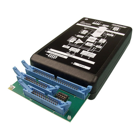
Data Translation
Data Translation DT9800 Series User manual
Data Translation
Data Translation DT8871 User manual
Data Translation
Data Translation DT9871 User manual
Data Translation
Data Translation DT9871U User manual
Data Translation
Data Translation DT9828 User manual
Popular Measuring Instrument manuals by other brands
Gentec-E
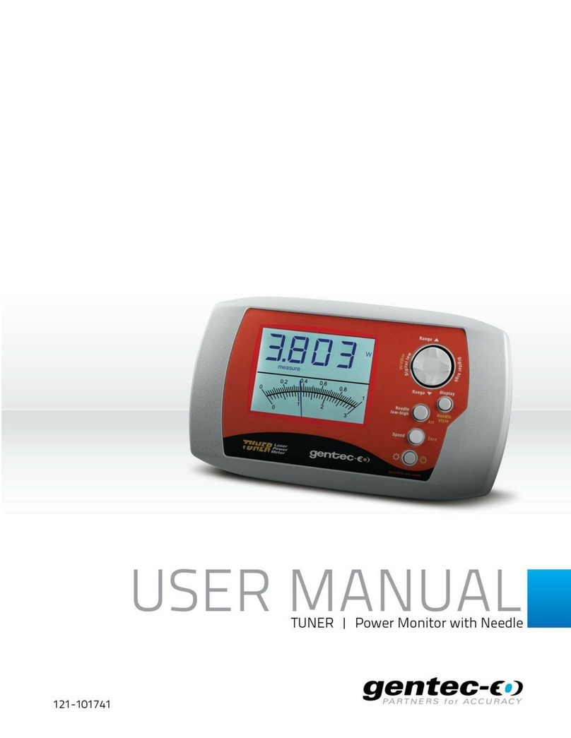
Gentec-E TUNER user manual
Unipulse
Unipulse F370 Operation manual
socomec
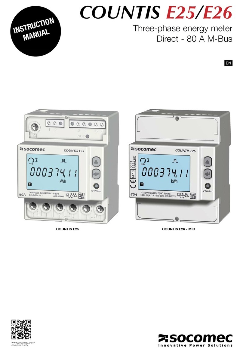
socomec COUNTIS E25 instruction manual

Hamamatsu
Hamamatsu ENERGETIQ LDLS EQ-99X Operation and maintenance manual

Bacharach
Bacharach Fyrite INTECH Configuration and operation manual

KROHNE
KROHNE M-PHASE 5000 Supplementary instructions

