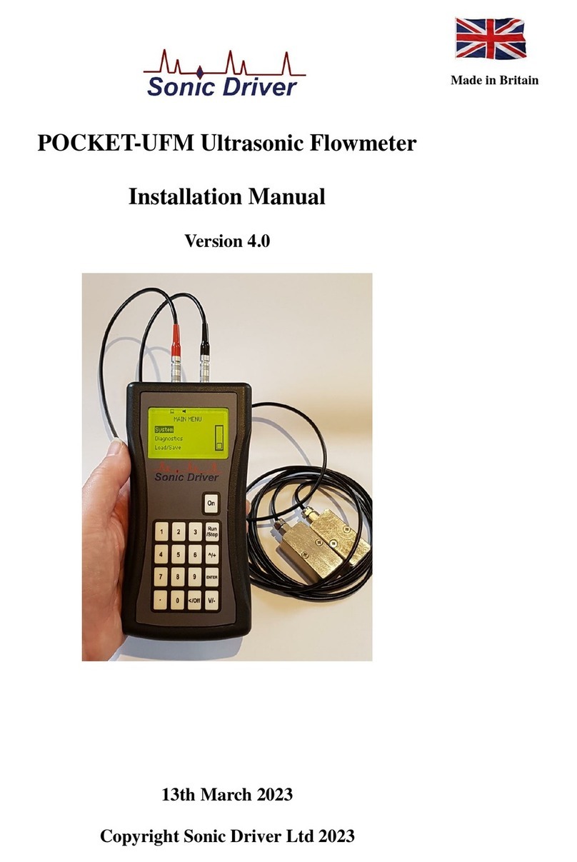
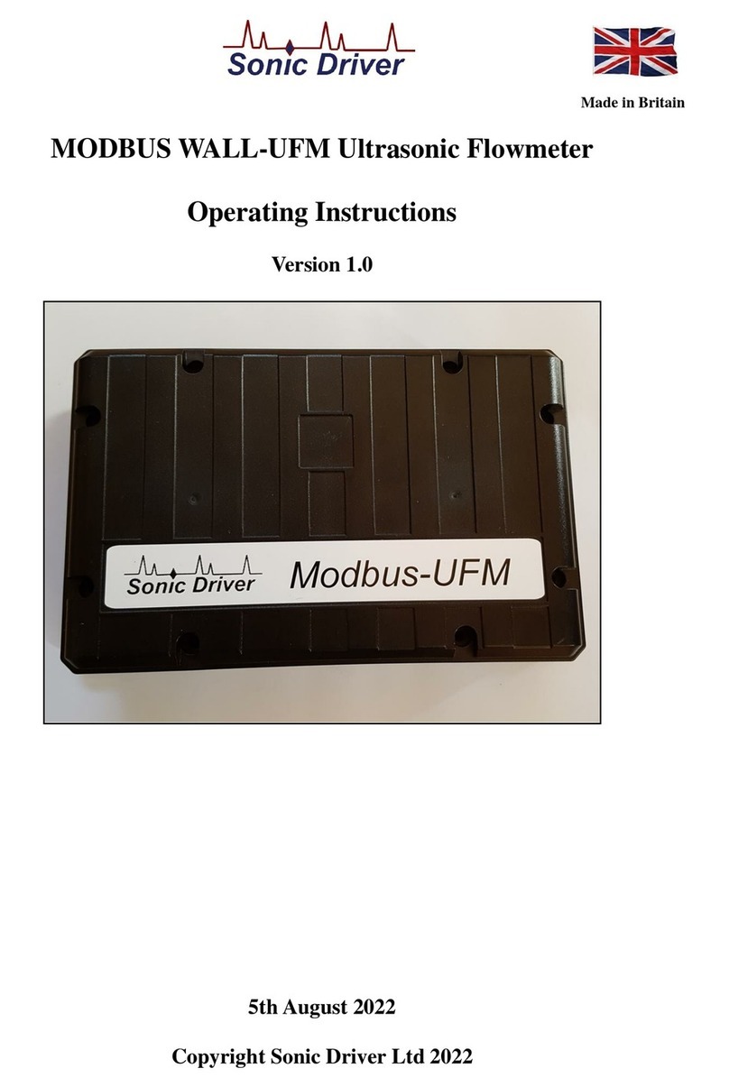
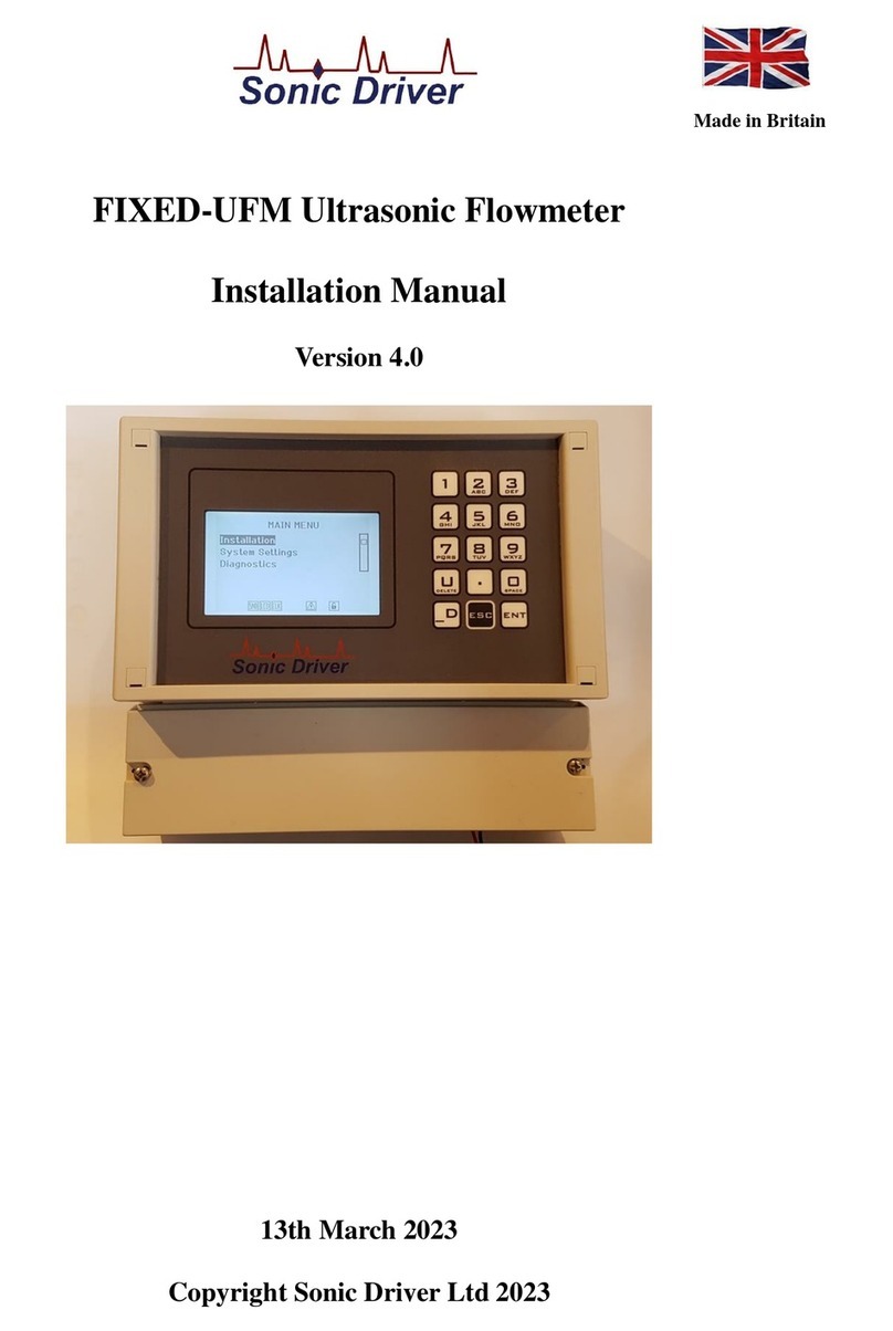
Sonic Driver POCKET PLUS-UFM User manual

Made in Britain
POCKET PLUS-UFM Ultrasonic Flowmeter
Operating Instructions
Version 3.0
13th March 2023
Copyright Sonic Driver Ltd 2023

Contents
1.0 Introduction
1.1 General Precautions
2.0 Keypad Functionality
3.0 FUNCTION KEY Functions
<1> Quick Start
<2> Transducer Positioning
<3>ATA/ETA %
<4> Flow Rate and Net Total
<5> Flow Velocity, Rate and Totals
<6> Flow Profile
<7> Energy Rate and Net Total
<8> Energy Rate and Totals
<9> Temperature
<.> Time Based Diagnostics
<0> Signal Based Diagnostics
4.0 Powering On
4.1 Power Off
5.0 User Interface (UI)
Quick Start Function
Installation Menu
Pipe Menu
Outer Diameter
Wall Thickness
Material
Roughness
Sound Velocity
WTG SOS
Liner Menu
Material
Sound Velocity
Thickness
Fluid Menu
Type
Temperature
Sound Velocity
Viscosity
Density
SHC
Inlet Temp
Outlet Temp
Transducer Menu
Type
Mounting
WTG Standoff

Calibration Settings Menu
Low Flow Cut
Corrected Flow
User Offset
User Scaling
Set Zero
Zero Tracking
Tup Method
Calculation Method
Display Units Menu
Flow Rate Units
Flow Rate Time Units
Totaliser Units
Energy Units
Energy Time Units
Measurement Units
Damping
Totalisers Menu
Net Flow Total
Pos Flow Total
Neg Flow Total
Flow Total Reset
Energy Total
Energy Total Reset
Load Defaults
System Settings Menu
LCD Backlit
Buzzer
Tag
Identifier
Test Display
Keypad
Memory
Clock
TOFM Scope
TOFM Values
Serial
Logger
System Info Menu
Model Code
Serial No.
HW Issue
SW Issue
Diagnostics Menu

Serial Menu
Mode
Baud
Parity
Logger Menu
Interval
Date
Time
Download
Erase
Load/Save Setups Menu
Save Option
Load Option
Delete Option
Appendix A Transducer parameters

1.0 Introduction
Congratulations on choosing the Sonic Driver TM POCKET PLUS-UFM TM clamp-on ultrasonic
flowmeter, figure(1).
Figure(1) The Sonic Driver POCKET PLUS-UFM.
The ultrasonic flowmeter (UFM) uses advanced Digital Signal Processing (DSP) and transit time
measurement techniques (Sonic Driver TM) to make accurate and reliable clamp-on ultrasonic flow
velocity measurements.
Using information about the installation, entered by the user, using the meters intuitive and easy to
us menu driven User Interface (UI) the UFM can display;
•Flow velocity
•Volumetric flow rate
•Mass flow rate
•Heat quantity flow rate
With the addition of a wall thickness measuring probe the UFM can also function as a pipe wall
thickness gauge (WTG).
The POCKET PLUS-UFM includes a date and time stamped 4MB datalogger and USB serial
communications functionality as standard.
When connected to a computer USB port or USB charger the UFM is powered over the USB. This
allows for extended datalogging sessions.

1.1 General Precautions
The content of this manual has been carefully checked and is believed to be accurate.
Sonic Driver Ltd assumes no responsibility for any inaccuracies that may be contained in this
manual.
In no event will Sonic Driver be liable for direct, indirect, special, incidental or consequential
damages resulting from any defect or omission in this manual, even if we are advised of the
possibility of such damages.
Sonic Driver Ltd reserves the right to make improvements to its manuals, instructions and products
at any time, without notice or obligation. The latest revisions may be found on the company web
site, www.sonic-driver.com
The UFM is a precision measuring instrument and should be handled and operated with care;
•Before operating the UFM for the first time read the installation manual and operating
instruction fully.
•Only use the UFM in the way and for the purpose that it is intended.
•Do not subject the UFM to bumps and shocks such as caused by dropping the UFM.
•Keep the UFM and its transducers and probes clean.
•Only use the UFM within its ambient temperature and stated level of Ingress Protection.
•Avoid excessive stress and bending of transducer cables and connectors.
•Avoid striking the clear display window and keypad with sharp objects.

2.0 Keypad Functionality
The UFM keypad offers several dual operation FUNCTION KEYS for quick setup and display.
Press any of the FUNCTION KEYS to go to the desired menu or display instantly. Note however
that depending on what the user is attempting to do the focus of certain keys will change.
On This key turns the flowmeter on.
When the user is navigating the UI and selecting a Menu screen;
1 Jump to MAIN MENU, the Quick Start option will be highlighted.
2 Jump to show Sensor Positioning screen, the user is prompted to select a
Transducer Type.
3 Jump to show ATA/ETA % diagnostic.
Run/Stop Jump to Measurement screen.
4 Jump to show Flow Rate and Net Total.
5 Jump to show flow velocity, flow rate, net, positive and negative flow totaliser.
6 Jump to show Reynolds Number, flow profile correction K Factor, Raw Flow
velocity and Corrected flow velocity.
^/+ Scroll up through Menu items.
7 Jump to show Energy Rate and Net Total.
8 Jump to show energy rate, net, positive and negative energy totaliser.
9 Jump to show Compensation, Inlet and Outlet temperature.
ENTER Step forward to selected Menu.
. Jump to show time based diagnostics.
0 Jump to show signal based diagnostics.
</Off Step back to previous Menu (When at Main Menu press and hold whilst progress bar
decrements to turn meter off).
V/- Scroll down through Menu items.
When the meter is in measurement mode and measuring the keypad keys have the following
functions;
1 Jump to MAIN MENU, the Quick Start option will be highlighted.
2 Jump to show Sensor Positioning screen, the user is prompted to select a
Transducer Type.
3 Jump to show ATA/ETA % diagnostic.
Run/Stop Jump to UI, show last menu accessed.
4 Jump to show Flow Rate and Net Total.
5 Jump to show flow velocity, flow rate, net, positive and negative flow totaliser.
6 Jump to show Reynolds Number, flow profile correction K Factor, Raw Flow
velocity and Corrected flow velocity.
^/+ Display contrast up.
7 Jump to show Energy Rate and Net Total.
8 Jump to show energy rate, net, positive and negative energy totaliser.
9 Jump to show Compensation, Inlet and Outlet temperature.
ENTER Step through all available display screens.
. Jump to show time based diagnostics.
0 Jump to show signal based diagnostics.
</Off No action.
V/- Display contrast down.

When the user is editing a parameter and the parameter editing cursor starts to flash the keypad keys
change function to become alphanumeric inputs;
1 Enter "1".
2 Enter "2".
3 Enter "3".
Run/Stop No action.
4 Enter "4".
5 Enter "5".
6 Enter "6".
^/+ Enter "+" symbol or scroll up though available parameter options in a list.
7 Enter "7".
8 Enter "8".
9 Enter "9".
ENTER Accept and Save changes and return to last Menu screen.
. Enter ".".
0 Enter "0".
</Off Return to last Menu screen, discard any changes.
V/- Enter "–" symbol or scroll down though available parameter options in a list.

3.0 FUNCTION KEY Functions
The keypad has a number of FUNCTION KEYS, which allow the user to instantly access functions;
<1> Quick Start
This key jumps to the Main Menu with the Quick Start option highlighted.
Press ENTER to start the Quick Start sequence or navigate the UI in the usual way.
<2> Transducer Positioning
This key gives access to a function which calculates the recommended transducer spacing and
displays diagnostics to aid transducer mounting and allows coupling optimization.
After entering the required Quick Start parameters, the spacing between the ends of the 2
transducers is calculated and displayed. Check the value displayed and space the transducers
accordingly.
If the Set Zero calibration function is enabled a zero flow calibration will also be made. It is vitally
important to ensure that there is zero flow during this procedure. If the UFM suspects that there is
flow in the pipe then a visual warning is given.
When the process is complete the user is returned to the UI.
<3>ATA/ETA %
This key gives access to a display of transit time ratio shown as a percentage value. This is a
measure of the ratio of the measured transit time to that which is expected given the parameters
entered by the user during Quick Start. It indicates if the transducer mounting and spacing is
accurate. The normal transit time ratio should be 100 ± 3% if the installation is correct.
It is acceptable to have to move one of the transducers up to ± 5mm to achieve a figure of 100%. If
more movement is necessary then one of the pipe parameters is probably incorrect. This is most
likely to be the value entered for pipe wall thickness as this is often taken from tables or it is an
estimated value.
<4> Flow Rate and Net Total
This key gives access to a display showing;
•Flow rate
•Net flow totaliser
<5> Flow Velocity, Rate and Totals
This key gives access to a display showing;
•Flow velocity
•Flow rate
•Net flow totaliser
•Positive flow totaliser

•Negative flow totaliser
Net total is simply the sum of the positive and negative flow totals.
<6> Flow Profile
This key gives access to a display showing;
•Reynolds Number
•Flow profile correction K factor
•Raw flow velocity
•Rolling average flow velocity
•Corrected flow velocity
The raw flow velocity is displayed without averaging and uncompensated for flow profile.
Rolling average flow velocity is raw flow velocity with average and flow profile compensation
applied.
Corrected flow velocity is rolling average flow velocity with zero flow cut off applied.
<7> Energy Rate and Net Total
This key gives access to a display showing;
•Energy rate
•Net energy totaliser
<8> Energy Rate and Totals
This key gives access to a display showing;
•Energy rate
•Net energy totaliser
•Positive energy totaliser
•Negative energy totaliser
<9> Temperature
This key gives access to a display showing;
•Fluid temperature
•Pipe inlet temperature
•Pipe outlet temperature
The fluid temperature is used for compensation of; speed of sound, density, viscosity and specific
heat capacity.

<.> Time Based Diagnostics
This display shows diagnostics relating to the timing measurements being made by the UFM.
•Delta Time
•Transit Time
•Path Time
•dT Offset
•SOS
The absolute upstream transit time through the fluid in the pipe and the absolute downstream transit
time through the fluid in the pipe are usually of the order of hundreds of microseconds. They are
very nearly identical. For this reason Transit Time is simply displaying the absolute upstream transit
time through the fluid in the pipe.
Delta Time is the difference in time between the two absolute transit times through the fluid. Delta
Time is of the order of tens of nanoseconds because the absolute upstream and downstream times
are so close together in value.
These values can help indicate the accuracy and condition of the installation. The measurement
calculations in the UFM are based upon these two values.
Therefore, when transit time difference fluctuates widely, the flow and velocities fluctuate
accordingly. This is usually accompanied by a signal strength and/or signal to noise ratio (SNR) that
is too low and varying. This may be the result of poor pipe installation conditions, inadequate
transducer installation, or incorrect parameter input. Generally, fluctuations should be less than ±
20%.
Path Time is the absolute upstream transit time through the entire ultrasonic path. This is different to
the absolute upstream transit time in the fluid as it includes time spent traversing the transducer
wedges, pipe and lining (if applicable). It is useful for fault finding with an oscilloscope as it is
referenced to a trigger signal available at a test point on the UFM PCB.
dT Offset is the offset value currently being used by the zero tracking function. This is usually in
the range ± 2.5ns.
SOS displays the expected and measured speed of sound in the fluid. It is used to calculate the value
of ATA/ETA %. Alarge difference (typically greater than ± 3%) can indicate something wrong in
the installation.
<0> Signal Based Diagnostics
This key gives access to a display showing diagnostics related to the signal strength and SNR of the
received sonic signal;
•Signal
•SNR
•Noise
•ATA/ETA
•Gain
Signal strength indicates the detected strength of the sonic signal in decibels (dB). Signal strength is

indicated by numbers from typically -25.0 to +55.0.
Normally, the stronger the signal strength detected the better and more reliable the flow
measurement is, as well as the more stable the measurement value obtained.
Adjust the transducer positioning to the best position, within limits and check to ensure that enough
sonic coupling compound is applied during installation in order to obtain the maximum signal
strength.
The UFM normally requires signal strength over 0.0dB to measure reliably. If the signal strength
detected is too low (is zero or negative), the transducer installation position and the transducer
mounting spacing should be adjusted and the pipe should be re-inspected. If necessary, change the
mounting method.
SNR indicates the quality of the sonic signal detected. SNR is indicated by numbers from typically
1.0 to 99.0, in dB.
represents the minimum SNR whilst 99.0 represents the maximum.
Normally, the transducer position should be adjusted and coupling compound application should be
checked until the SNR detected is as large as possible.
The UFM normally requires SNR over 12.0dB to measure reliably.
Noise indicates the level of extraneous sonic and electrical noise being detected in dB. Noise is
indicated by numbers from typically -25.0 to +55.0.
The UFM normally requires noise strength below +10.0dB to measure reliably.
Gain indicates the amount of electronic gain being used by the UFM receiver amplifier. Gain is
indicated by numbers from typically 0.0 to 81.0, in dB.
0.0 represents the minimum gain whilst 81.0 represents the maximum.
Old pipes, attenuating pipes, corrosion, attenuating fluids, etc. can require the UFM to automatically
turn up its gain.
The UFM normally operates with a gain typically around 30.0 to 60.0dB.
ATA/ETA% or transit time ratio indicates if the transducer mounting spacing is accurate. The
normal transit time ratio should be 100 ±3% if the installation is correct.
The Installation Manual that accompanies these Operating Instructions gives more details regarding
mounting, coupling and spacing the transducers correctly.

4.0 Powering On
To power on a POCKET-UFM press and hold the On key.
As soon as the UFM is switched on a self diagnostic program will start.
If an error is detected an error message will be displayed prompting user action. If the error persists
contact customer support.
Error codes and their meanings can be found in the Diagnostics Menu.
Alternatively, when connected to a computer USB port or USB charger the UFM is powered over
the USB and will power on automatically. This allows for extended datalogging sessions.
4.1 Power Off
From the Main Menu press and hold the “</Off” key.
A progress bar decrements to turn the meter off.
If the “</Off” key is released before the progress bar fully decrements the meter returns to the
Measurement screen.
If there is no keypad activity in UI mode for 60 seconds then the UFM will automatically power off.
Automatic power off does not apply in Measure mode.
To fully power down the UFM it is also necessary to disconnect the USB if it is connected.

5.0 User Interface (UI)
The Main Menu allows the user to select a group of parameters to edit or a meter function;
•Quick Start
•Installation
•System
•Diagnostics
•Serial
•Logger
•Load/Save

Quick Start Function
The Quick Start function takes the user through the minimum sequence of parameters needed to get
the UFM measuring reliably and accurately;
•Transducer Type
•Transducer Mounting
•Pipe Diameter
•Pipe Wall Thickness
•Pipe Material
•Liner Material
•Fluid
•Fluid Temperature
Each parameter is described below in the relevant section.
After selecting Transducer Type and Transducer Mounting it is also possible to jump to the end of
the sequence by pressing the Run/Stop key.
If Transducer Type WTG (Wall Thickness Gauge) is selected then the sequence of parameters
changes to;
•Transducer Type
•Pipe Material
and the UFM enters a wall thickness measuring mode. To make use of this feature the user must
purchase an additional WTG probe as well as a pair of flow measurement transducers. Contact
Sales for details.
When operating as a wall thickness gauge the user can scroll between 3 display modes by
repeatedly pressing the “Enter” key, the modes are;
•Full display of wall thickness measurement and all measurement diagnostics.
•A-Scan showing the raw received ultrasonic signal.
•Processed signal showing the measured signal corresponding to the wall thickness.

Installation Menu
The Installation Menu allows the user to edit parameters specific to the physical installation of the
UFM on a pipe;
•Pipe
•Liner
•Fluid
•Transducer
•Calibration
•Display Units
•Totaliser
•Load Defaults
These parameters represent an extended set of parameters needed to get the UFM measuring and
displaying values, above and beyond the very basic parameter set used by the Quick Start sequence.

Pipe Menu
This menu allows the user to change pipe settings. A test is made to check that the parameters that
are entered do not result in a Closed Pipe.
Outer Diameter
The user is prompted to enter a value for the pipe outer diameter. Allowed values are ranged 10.0 to
6500.0mm, default 60.6mm.
Wall Thickness
The user is prompted to enter a value for the pipe wall thickness.Allowed values are ranged 0.5 to
100.0mm, default 3.2mm.
Material
The user can select the pipe material from a list;
•Carbon Steel (Default)
•Stainless 304
•Stainless 316
•Cast Iron
•Ductile Iron
•Copper
•PVC
•Lead
•Nylon
•PE
•Aluminium
•Asbestos
•Fibre Glass
•Other
If Other is selected then the user is prompted to enter the transverse (shear) speed of sound in the
pipe material, see below. Otherwise the transverse speed of sound in the pipe material is read from a
database held in the UFM.
Roughness
The user is prompted to enter a value for the peak/trough height of the roughness on the inside
surface of the pipe. Allowed values are ranged 0.001 to 10.000mm, default 0.010mm.
If a liner material is selected then this roughness is automatically transposed and applied to the inner
surface of the lining.
This value is used in flow profile correction calculations.
Sound Velocity
Appearance of this parameter is context driven. If the Pipe Material is entered as Other then the user

is prompted to enter a pipe transverse sound velocity.
The user is prompted to enter the transverse speed of sound in the pipe.Allowed values are ranged
500 to 7000m/s, default 3206m/s (Carbon Steel default).
WTG SOS
This value is used to make wall thickness measurements using the UFM when fitted with a wall
thickness probe rather than flow transducers, see the Transducer Type parameter below.
Appearance of this parameter is context driven. If the Material is entered as Other then the user is
prompted to enter a pipe longitudinal sound velocity.
The user is prompted to enter the longitudinal speed of sound in the pipe. Allowed values are ranged
500 to 7000m/s, default 6412m/s (Carbon Steel default).

Liner Menu
This menu allows the user to change pipe lining settings.
Material
The user can select a pipe liner material from a list;
•None (Default)
•Cement
•Epoxy
•Glass
•PP
•Teflon
•Rubber
•Other
The list allows no liner (None) to be selected.
Sound Velocity
Appearance of this parameter is context driven. If the user selected Other from the list of liner
materials then the user is prompted to enter the transverse speed of sound in the liner material.
Otherwise the speed of sound in the liner material is read from a database held in the UFM.
Allowed values are ranged 500 to 7000m/s, default 0m/s (None).
Thickness
Appearance of this parameter is context driven. If the user selected a liner then the user is prompted
for the thickness of the liner. Allowed values are ranged 0.5 to 100.0mm, default 0.0mm (None).

Fluid Menu
This menu allows the user to change fluid settings.
Type
The user can select the fluid in the pipe from a list;
•Water (Default)
•Sea Water
•Kerosene
•Petrol
•Fuel Oil
•Crude Oil
•Freon R134a
•Freon R22
•Diesel Oil
•Castor Oil
•F-76 Fuel Oil
•Novec 1230
•Glycol/Water
•Alcohol
•Other
If the user selected Other from the list of fluid types then the user is prompted to enter various
context driven parameters, see below.
Temperature
The user is prompted to enter the temperature of the fluid in the pipe.Allowed values are ranged -20
to +150 degC, default 18 degC.
Changing Fluid Temperature causes Fluid Sound Velocity, Fluid Kinematic Viscosity, Fluid Density
and Fluid Specific Heat Capacity to be recalculated.
Sound Velocity
Appearance of this parameter is context driven. If the user selected Other from the list of fluid types
then the user is prompted to enter the longitudinal speed of sound in the fluid (NOTE not transverse
as this type of wave is not supported in fluids). Otherwise the longitudinal speed of sound in the
fluid is read from a database held in the UFM.
The user is prompted to enter the longitudinal speed of sound in the fluid. Allowed values are
ranged 50 to 4000m/s, default 1475m/s (Water at 18degC).
Viscosity
Appearance of this parameter is context driven. If the user selected Other from the list of fluid types
then the user is prompted to enter the kinematic viscosity of the fluid. Otherwise the kinematic
Table of contents
Other Sonic Driver Measuring Instrument manuals
Popular Measuring Instrument manuals by other brands
GREISINGER
GREISINGER GMH 3610 operating manual

BRUEL & KJAER
BRUEL & KJAER HBK Z6AM Mounting instructions
Coster
Coster IET 7143 C1 Wiring diagram
DEVA Broadcast
DEVA Broadcast Band Scanner PRO Quick user guide
EUTECH INSTRUMENTS
EUTECH INSTRUMENTS CyberScan IR TB100 instruction manual
Edmunds Gages
Edmunds Gages Trendsetter II user manual
