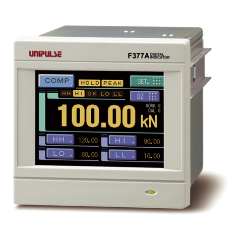
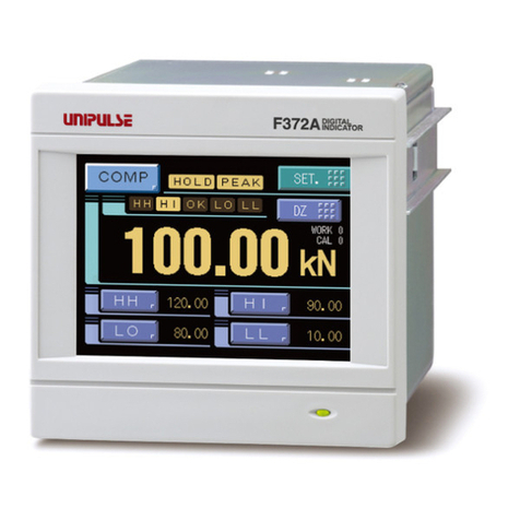
Unipulse F370 User manual

F370
DIGITAL INDICATOR
20 Jul. 2011
Rev. 1.19
OPERATION MANUAL

Cautions and Requests for Use
●Do not disassemble the main body for modifications or repair.
●Be sure to use crimp contacts for connection to terminal blocks, and do not to
connect bare wires as they are.
●Be sure to ground the protective ground terminal.
●Be sure to disconnect the power cable when performing the following.
- Attachment/detachment of connectors of options.
- Wiring/connection of cables to terminal blocks.
- Connection of the ground line.
●Carefully check wiring, etc. before applying power.
●Take an interval of more than 5 seconds when repeating ON/OFF.
●Take adequate shielding measures when using at the following locations.
- Near a power line.
- Where a strong electric field or magnetic field is formed.
- Where static electricity, relay noise or the like is generated.
●Do not install in the following environments.
- Placesexposed to direct sunlight.
- Where the temperature and/or humidity exceeds the range in the
specifications.
- Placescontaining corrosive gas or flammable gas.
- Placeswith large quantities of dust, salt or iron powder.
- Where the product may be splashed with water, oil or chemicals.
- Where the main body is directly affected by vibration or shock.
●Set the correct Excitation Voltage for the sensor. (2.5V is set when F370 is
dispatched from us.)

Safety Precautions
Safety Precautions
●Indications for safe use and their meanings
In this manual, precautions for using the F370 digital indicator safely are indicated as
follows. Be sure to follow the precautions given here because they are important
descriptions relating to safety.
Indications and their meanings are as follows:
●Explanation of pictographs
The △means a caution (or warning).
A specific description is written in the △.
The illustration on the left-hand side shows "Caution: May explode".
The △means a caution (or warning).
A specific description is written in the △.
The illustration on the left-hand side shows a general caution.
WARNING
Misuse may cause the risk of death or serious
injury to persons.
Misuse may cause the risk of injury to persons or
damage to property.
CAUTION

Safety Precautions
●About the built-in lithium battery
●About the signal I/O terminal block
Never disassemble, deform under pressure or throw the battery
into fire.The battery may explode, catch fire or leak.
- Battery
Model: CR2477-1HF made by Matsushita Battery Industrial Co., Ltd.
Nominal voltage: 3V
Nominal electric capacity: 1000mAh
WARNING
For connection to the signal I/O terminal block, wire correctly after
checking the signal names and terminal block numbers.
Also, turn off the power of the main body before connection/wiring to the
signal I/O terminal block.
CAUTION

CONTENTS
CONTENTS
1.APPEARANCE DESCRIPTION . . . . . . . . . . . . . . . . . . . . . . . . .1
1-1.Front Panel . . . . . . . . . . . . . . . . . . . . . . . . . . . . . . . . . . . . . . . . . . . .1
1-1-1.Touch Panel Display . . . . . . . . . . . . . . . . . . . . . . . . . . . . . . . . . . . . . . . . . . . . . 1
1-1-2.Power Lamp . . . . . . . . . . . . . . . . . . . . . . . . . . . . . . . . . . . . . . . . . . . . . . . . . . . 1
1-2.Rear Panel . . . . . . . . . . . . . . . . . . . . . . . . . . . . . . . . . . . . . . . . . . . . .2
1-2-1.Signal I/O Terminal Block . . . . . . . . . . . . . . . . . . . . . . . . . . . . . . . . . . . . . . . . . 2
1-2-2.AC Power Source Input Terminal Block . . . . . . . . . . . . . . . . . . . . . . . . . . . . . . 4
1-2-3.Frame Ground (Functional ground) . . . . . . . . . . . . . . . . . . . . . . . . . . . . . . . . . 4
1-2-4.Optional Slot . . . . . . . . . . . . . . . . . . . . . . . . . . . . . . . . . . . . . . . . . . . . . . . . . . . 4
2.SETTING MODES . . . . . . . . . . . . . . . . . . . . . . . . . . . . . . . . . . .5
2-1.F370 Screen Configuration . . . . . . . . . . . . . . . . . . . . . . . . . . . . . . . .5
2-2.Setting Modes Tree . . . . . . . . . . . . . . . . . . . . . . . . . . . . . . . . . . . . . .6
2-3.About a Setting Call . . . . . . . . . . . . . . . . . . . . . . . . . . . . . . . . . . . . . .8
3.CONNECTION . . . . . . . . . . . . . . . . . . . . . . . . . . . . . . . . . . . . . .9
3-1.Connection with Power Source Input Terminal . . . . . . . . . . . . . . . . .9
3-2.Load Cell Connection . . . . . . . . . . . . . . . . . . . . . . . . . . . . . . . . . . .10
3-3.SI/F Connection . . . . . . . . . . . . . . . . . . . . . . . . . . . . . . . . . . . . . . . .11
3-4.External I/O Connection . . . . . . . . . . . . . . . . . . . . . . . . . . . . . . . . . .12
3-4-1.External Output Connection . . . . . . . . . . . . . . . . . . . . . . . . . . . . . . . . . . . . . . 12
3-4-2.External Input Connection . . . . . . . . . . . . . . . . . . . . . . . . . . . . . . . . . . . . . . . 12
3-4-3.Connecting to Cage Clamp Terminal Block . . . . . . . . . . . . . . . . . . . . . . . . . . 13
4.CALIBRATION . . . . . . . . . . . . . . . . . . . . . . . . . . . . . . . . . . . . .14
4-1.Equivalent Input Calibration Procedure . . . . . . . . . . . . . . . . . . . . . .15
4-2.Actual Load Calibration Procedure . . . . . . . . . . . . . . . . . . . . . . . . .16
4-3.Zero Calibration . . . . . . . . . . . . . . . . . . . . . . . . . . . . . . . . . . . . . . . .17
4-4.Actual Load Calibration . . . . . . . . . . . . . . . . . . . . . . . . . . . . . . . . . .18

CONTENTS
4-5.Equivalent Input Calibration . . . . . . . . . . . . . . . . . . . . . . . . . . . . . . .19
4-6.Digital Offset . . . . . . . . . . . . . . . . . . . . . . . . . . . . . . . . . . . . . . . . . .21
4-7.Increment (This step may be omitted if there is no change.) . . . . . .22
4-8.Decimal Place . . . . . . . . . . . . . . . . . . . . . . . . . . . . . . . . . . . . . . . . .23
4-9.Calibration Protection . . . . . . . . . . . . . . . . . . . . . . . . . . . . . . . . . . .24
4-10.Calibration Value Selection . . . . . . . . . . . . . . . . . . . . . . . . . . . . . .25
4-11.Unit . . . . . . . . . . . . . . . . . . . . . . . . . . . . . . . . . . . . . . . . . . . . . . . .27
5.SETTING OF FUNCTIONS . . . . . . . . . . . . . . . . . . . . . . . . . . .28
5-1.Digital Zero . . . . . . . . . . . . . . . . . . . . . . . . . . . . . . . . . . . . . . . . . . .28
5-2.Digital Filter . . . . . . . . . . . . . . . . . . . . . . . . . . . . . . . . . . . . . . . . . . .29
5-3.Analog Filter . . . . . . . . . . . . . . . . . . . . . . . . . . . . . . . . . . . . . . . . . . .30
5-4.Display Rate . . . . . . . . . . . . . . . . . . . . . . . . . . . . . . . . . . . . . . . . . .30
5-5.Stability . . . . . . . . . . . . . . . . . . . . . . . . . . . . . . . . . . . . . . . . . . . . . .31
5-6.Zero Track . . . . . . . . . . . . . . . . . . . . . . . . . . . . . . . . . . . . . . . . . . . .32
5-7.Contrast Adjustment . . . . . . . . . . . . . . . . . . . . . . . . . . . . . . . . . . . .33
5-8.Backlight . . . . . . . . . . . . . . . . . . . . . . . . . . . . . . . . . . . . . . . . . . . . .33
5-9.Excitation Voltage . . . . . . . . . . . . . . . . . . . . . . . . . . . . . . . . . . . . . .33
5-10.Auto Print . . . . . . . . . . . . . . . . . . . . . . . . . . . . . . . . . . . . . . . . . . . .34
5-11.Hold Off Print . . . . . . . . . . . . . . . . . . . . . . . . . . . . . . . . . . . . . . . . .36
5-12.Parameter Protection . . . . . . . . . . . . . . . . . . . . . . . . . . . . . . . . . . .36
6.COMPARISON FUNCTIONS . . . . . . . . . . . . . . . . . . . . . . . . . .37
6-1.HI Limit/LO Limit/HI-HI Limit/LO-LO Limit . . . . . . . . . . . . . . . . . . . .38
6-2.Hysteresis . . . . . . . . . . . . . . . . . . . . . . . . . . . . . . . . . . . . . . . . . . . .39
6-3.Near Zero . . . . . . . . . . . . . . . . . . . . . . . . . . . . . . . . . . . . . . . . . . . . .41
6-4.HI-LO Limit Comparison Mode . . . . . . . . . . . . . . . . . . . . . . . . . . . .41
6-5.HI-LO Limit Output Mode . . . . . . . . . . . . . . . . . . . . . . . . . . . . . . . . .42
6-6.Alarm Mode . . . . . . . . . . . . . . . . . . . . . . . . . . . . . . . . . . . . . . . . . . .43

CONTENTS
7.HOLD FUNCTIONS . . . . . . . . . . . . . . . . . . . . . . . . . . . . . . . . .44
7-1.Hold Setting --- common --- . . . . . . . . . . . . . . . . . . . . . . . . . . . . . .44
7-1-1.Hold Mode . . . . . . . . . . . . . . . . . . . . . . . . . . . . . . . . . . . . . . . . . . . . . . . . . . . 44
7-1-2.Hold Detection Time . . . . . . . . . . . . . . . . . . . . . . . . . . . . . . . . . . . . . . . . . . . . 45
7-1-3.Auto Start Level . . . . . . . . . . . . . . . . . . . . . . . . . . . . . . . . . . . . . . . . . . . . . . . 46
7-1-4.Hold Point Shift . . . . . . . . . . . . . . . . . . . . . . . . . . . . . . . . . . . . . . . . . . . . . . . . 46
7-2.Hold Setting --- relative maximum and relative minimum --- . . . . .47
7-2-1.Minimum Count . . . . . . . . . . . . . . . . . . . . . . . . . . . . . . . . . . . . . . . . . . . . . . . 48
7-2-2.Valley Detection Level . . . . . . . . . . . . . . . . . . . . . . . . . . . . . . . . . . . . . . . . . . 48
7-3.Hold Setting --- inflection point --- . . . . . . . . . . . . . . . . . . . . . . . . .49
7-3-1.Minimum Slope . . . . . . . . . . . . . . . . . . . . . . . . . . . . . . . . . . . . . . . . . . . . . . . . 50
7-3-2.Interval A and Interval B . . . . . . . . . . . . . . . . . . . . . . . . . . . . . . . . . . . . . . . . . 50
7-4.Hold Setting --- mean value --- . . . . . . . . . . . . . . . . . . . . . . . . . . .52
7-4-1.Mean Value Sampling Count . . . . . . . . . . . . . . . . . . . . . . . . . . . . . . . . . . . . . 52
7-5.Hold Operation . . . . . . . . . . . . . . . . . . . . . . . . . . . . . . . . . . . . . . . . .53
7-5-1.Sample Hold . . . . . . . . . . . . . . . . . . . . . . . . . . . . . . . . . . . . . . . . . . . . . . . . . . 53
7-5-2.Peak Hold . . . . . . . . . . . . . . . . . . . . . . . . . . . . . . . . . . . . . . . . . . . . . . . . . . . . 54
7-5-3.Valley Hold . . . . . . . . . . . . . . . . . . . . . . . . . . . . . . . . . . . . . . . . . . . . . . . . . . . 55
7-5-4.Peak-to-Peak (P-P) Hold . . . . . . . . . . . . . . . . . . . . . . . . . . . . . . . . . . . . . . . . 56
7-5-5.Relative Maximum and Relative Minimum Hold . . . . . . . . . . . . . . . . . . . . . . . 57
7-5-6.Inflection Point Hold . . . . . . . . . . . . . . . . . . . . . . . . . . . . . . . . . . . . . . . . . . . . 59
7-5-7.Mean Value Hold . . . . . . . . . . . . . . . . . . . . . . . . . . . . . . . . . . . . . . . . . . . . . . 60
7-6.How to Specify the Hold Detection Period . . . . . . . . . . . . . . . . . . . .61
7-6-1.All Period . . . . . . . . . . . . . . . . . . . . . . . . . . . . . . . . . . . . . . . . . . . . . . . . . . . . 61
7-6-2.Externally Specified Period Hold
(Peak, Valley, Peak-to-Peak and Mean Value) . . . . . . . . . . . . . . . . . . . . . . . 62
7-6-3.Time Specified Period Hold
(Peak, Valley, Peak-to-Peak and Mean Value) . . . . . . . . . . . . . . . . . . . . . . . 63
7-6-4.Time Specified Period Hold with Trigger
(Peak, Valley, Peak-to-Peak and Mean Value) . . . . . . . . . . . . . . . . . . . . . . . 64
8.MULTI-HOLD FUNCTION . . . . . . . . . . . . . . . . . . . . . . . . . . . .65
8-1.About Changing of the Setting CH . . . . . . . . . . . . . . . . . . . . . . . . . .66
CONTENTS
9.WAVEFORM DISPLAY . . . . . . . . . . . . . . . . . . . . . . . . . . . . . .67
9-1.Graphic Display Screen . . . . . . . . . . . . . . . . . . . . . . . . . . . . . . . . . .67
9-1-1.Hold Point Plotting . . . . . . . . . . . . . . . . . . . . . . . . . . . . . . . . . . . . . . . . . . . . . 68
9-1-2.X-axis and Y-axis on the Graph Plotting Screen . . . . . . . . . . . . . . . . . . . . . . 68
9-2.Graph Plotting . . . . . . . . . . . . . . . . . . . . . . . . . . . . . . . . . . . . . . . . .69
9-2-1.Continuous . . . . . . . . . . . . . . . . . . . . . . . . . . . . . . . . . . . . . . . . . . . . . . . . . . . 69
9-2-2.External . . . . . . . . . . . . . . . . . . . . . . . . . . . . . . . . . . . . . . . . . . . . . . . . . . . . . 70
9-2-3.Level . . . . . . . . . . . . . . . . . . . . . . . . . . . . . . . . . . . . . . . . . . . . . . . . . . . . . . . . 71
9-2-4.External + Level . . . . . . . . . . . . . . . . . . . . . . . . . . . . . . . . . . . . . . . . . . . . . . . 71
9-3.Graph Function . . . . . . . . . . . . . . . . . . . . . . . . . . . . . . . . . . . . . . . .72
9-4.Interval Time . . . . . . . . . . . . . . . . . . . . . . . . . . . . . . . . . . . . . . . . . .72
9-5.Graph Start Level . . . . . . . . . . . . . . . . . . . . . . . . . . . . . . . . . . . . . . .72
9-6.Level Detection Mode . . . . . . . . . . . . . . . . . . . . . . . . . . . . . . . . . . .73
9-7.X Start Point . . . . . . . . . . . . . . . . . . . . . . . . . . . . . . . . . . . . . . . . . . .74
9-8.Y (Load) Start Point and Y (Load) End Point . . . . . . . . . . . . . . . . . .74
10.BCD DATA OUTPUT(OPTION) . . . . . . . . . . . . . . . . . . . . . . .75
10-1.Connector Pin Assignment . . . . . . . . . . . . . . . . . . . . . . . . . . . . . .75
10-2.Logic Change . . . . . . . . . . . . . . . . . . . . . . . . . . . . . . . . . . . . . . . . .76
10-3.BCD Data Hold . . . . . . . . . . . . . . . . . . . . . . . . . . . . . . . . . . . . . . .76
10-4.Equivalent Circuit . . . . . . . . . . . . . . . . . . . . . . . . . . . . . . . . . . . . . .76
10-5.Signal Timing . . . . . . . . . . . . . . . . . . . . . . . . . . . . . . . . . . . . . . . . .77
10-6.BCD Data Update Rate Selection . . . . . . . . . . . . . . . . . . . . . . . . .78
10-7.BCD Output Data Selection . . . . . . . . . . . . . . . . . . . . . . . . . . . . . .78
11.RS-232C INTERFACE(OPTION) . . . . . . . . . . . . . . . . . . . . . .79
11-1.Communication Specifications . . . . . . . . . . . . . . . . . . . . . . . . . . . .79
11-1-1.Specifications . . . . . . . . . . . . . . . . . . . . . . . . . . . . . . . . . . . . . . . . . . . . . . . . 79
11-1-2.Connector Pin Assignment . . . . . . . . . . . . . . . . . . . . . . . . . . . . . . . . . . . . . . 80
11-1-3.Cable . . . . . . . . . . . . . . . . . . . . . . . . . . . . . . . . . . . . . . . . . . . . . . . . . . . . . . 80

CONTENTS
11-2.RS-232C Interface Setting . . . . . . . . . . . . . . . . . . . . . . . . . . . . . . .81
11-2-1.Communication Mode . . . . . . . . . . . . . . . . . . . . . . . . . . . . . . . . . . . . . . . . . . 81
11-2-2.Baud Rate . . . . . . . . . . . . . . . . . . . . . . . . . . . . . . . . . . . . . . . . . . . . . . . . . . . 81
11-2-3.Character Length . . . . . . . . . . . . . . . . . . . . . . . . . . . . . . . . . . . . . . . . . . . . . 81
11-2-4.Parity Bit . . . . . . . . . . . . . . . . . . . . . . . . . . . . . . . . . . . . . . . . . . . . . . . . . . . . 81
11-2-5.Stop Bit . . . . . . . . . . . . . . . . . . . . . . . . . . . . . . . . . . . . . . . . . . . . . . . . . . . . . 82
11-2-6.Terminator . . . . . . . . . . . . . . . . . . . . . . . . . . . . . . . . . . . . . . . . . . . . . . . . . . 82
11-3.Communication Modes . . . . . . . . . . . . . . . . . . . . . . . . . . . . . . . . .82
11-4.Communication Format . . . . . . . . . . . . . . . . . . . . . . . . . . . . . . . . .83
12.RS-485 COMMUNICATION INTERFACE(OPTION) . . . . . . .90
12-1.Communication Specifications . . . . . . . . . . . . . . . . . . . . . . . . . . . .90
12-2.RS-485 connection . . . . . . . . . . . . . . . . . . . . . . . . . . . . . . . . . . . .90
12-3.Communication Method . . . . . . . . . . . . . . . . . . . . . . . . . . . . . . . . .93
12-4.RS-485 Interface Setting . . . . . . . . . . . . . . . . . . . . . . . . . . . . . . . .94
12-4-1.ID . . . . . . . . . . . . . . . . . . . . . . . . . . . . . . . . . . . . . . . . . . . . . . . . . . . . . . . . . 94
12-4-2.Terminator Resistance . . . . . . . . . . . . . . . . . . . . . . . . . . . . . . . . . . . . . . . . . 94
12-4-3.Communication Method . . . . . . . . . . . . . . . . . . . . . . . . . . . . . . . . . . . . . . . . 94
13.D/A CONVERTER(OPTION) . . . . . . . . . . . . . . . . . . . . . . . . .95
13-1.Voltage Zero and Full Scale, Current Zero and Full Scale . . . . . .96
13-2.D/A Output Mode . . . . . . . . . . . . . . . . . . . . . . . . . . . . . . . . . . . . . .97
13-3.Voltage Output Selection . . . . . . . . . . . . . . . . . . . . . . . . . . . . . . . .97
13-4.Current Output Selection . . . . . . . . . . . . . . . . . . . . . . . . . . . . . . . .97
14.DC POWER SOURCE . . . . . . . . . . . . . . . . . . . . . . . . . . . . . .99
15.ERROR MESSAGES . . . . . . . . . . . . . . . . . . . . . . . . . . . . . .100

CONTENTS
16.SELF-CHECK AND INITIALIZATION . . . . . . . . . . . . . . . . .101
16-1.Self-Check . . . . . . . . . . . . . . . . . . . . . . . . . . . . . . . . . . . . . . . . . .101
16-1-1.Self-Check DSP . . . . . . . . . . . . . . . . . . . . . . . . . . . . . . . . . . . . . . . . . . . . . 101
16-1-2.Self-Check MEM . . . . . . . . . . . . . . . . . . . . . . . . . . . . . . . . . . . . . . . . . . . . . 101
16-1-3.Self-Check KEY . . . . . . . . . . . . . . . . . . . . . . . . . . . . . . . . . . . . . . . . . . . . . 102
16-1-4.Self-Check EXT . . . . . . . . . . . . . . . . . . . . . . . . . . . . . . . . . . . . . . . . . . . . . 102
16-2.Initialization (All setting value clearances) . . . . . . . . . . . . . . . . . .103
16-3.Password . . . . . . . . . . . . . . . . . . . . . . . . . . . . . . . . . . . . . . . . . . .103
17.ABOUT JAPANESE/ENGLISH DISPLAY SELECTION . . .104
18.BLOCK DIAGRAM . . . . . . . . . . . . . . . . . . . . . . . . . . . . . . . .105
19.DIMENSIONS . . . . . . . . . . . . . . . . . . . . . . . . . . . . . . . . . . . .106
20.INSTALLATION IN A PANEL . . . . . . . . . . . . . . . . . . . . . . .107
21.SPECIFICATIONS . . . . . . . . . . . . . . . . . . . . . . . . . . . . . . . .108
21-1.Analog Section . . . . . . . . . . . . . . . . . . . . . . . . . . . . . . . . . . . . . . .108
21-2.Digital Section . . . . . . . . . . . . . . . . . . . . . . . . . . . . . . . . . . . . . . .108
21-3.Options . . . . . . . . . . . . . . . . . . . . . . . . . . . . . . . . . . . . . . . . . . . .109
21-4.External Input and Output . . . . . . . . . . . . . . . . . . . . . . . . . . . . . .110
21-5.General . . . . . . . . . . . . . . . . . . . . . . . . . . . . . . . . . . . . . . . . . . . .111
21-6.Accessories . . . . . . . . . . . . . . . . . . . . . . . . . . . . . . . . . . . . . . . . .112
22.SETTING ITEM CHART . . . . . . . . . . . . . . . . . . . . . . . . . . . .113
23.CONFORMITY TO EC DIRECTIVES . . . . . . . . . . . . . . . . . .117

CONTENTS

1.APPEARANCE DESCRIPTION
1
1. APPEARANCE DESCRIPTION
1-1. Front Panel
1-1-1. Touch Panel Display
This is the touch panel display for displaying an indicated value and graph set value and
for setting various setting items of the F370. During measurement, a comparison display,
hold display and graph display can be selected according to the function in use.
1-1-2. Power Lamp
This lamp lights when the power to the F370 is on.
Touch Panel
Display
Power Lamp
Hold Status Display
Display Change Button
Comparison Status
Indicated Value
Setting Input Screen
Call Button
Digital Zero
Button
Setting Mode
Button
Display
Display
Comparison Display Hold Display Graph Display

1.APPEARANCE DESCRIPTION
2
1-2. Rear Panel
1-2-1. Signal I/O Terminal Block
Frame ground
Signal I/O terminal
Optional slot
AC power source
input terminal block block
Pin assignments
D/Z In A11 B11 SIF Out
H/M In A10 B10 SIF Out
T/H In A9 B9 ST/SP In
CODE2 In A8 B8 CODE3 In
CODE0 In A7 B7 CODE1 In
COM2 ※A6 B6 H/E Out
HH Out A5 B5 LL Out
HI Out A4 B4 LO Out
COM1 ※A3 B3 OK Out
-EXC Out A2 B2 -SIG In
+EXC Out A1 B1 +SIG In

1.APPEARANCE DESCRIPTION
3
See the section on Load Cell Connection page 10 for connection.
See the section on External I/O Connection page 12 for connection.
See the section on SI/F Connection page 11 for connection.
+EXC
-EXC
+SIG
-SIG
The terminal for connecting to a strain-gage sensor.
COM1 The terminal common to output signals.
OK
HI
LO
HH
LL
Outputs the OK signal.
Outputs the HI signal.
Outputs the LO signal.
Outputs the HH signal.
Outputs the LL signal.
H/E Outputs the hold end signal.
→page44「HOLD FUNCTIONS」
COM2 The terminal common to input signals.
CODE0
CODE1
CODE2
CODE3
Selects the CH No. for the multi-hold function.
→page65「MULTI-HOLD FUNCTION」
T/H
H/M
D/Z The input for digital zero (making the indicated value zero).
→page28「Digital Zero」
ST/SP The graphic display start/stop signal.
→page69「Graph Plotting」
SI/F The 2-wire serial interface for coupling a UNIPULSE printer,
external display, etc.
「COMPARISON
FUNCTIONS」
→page 37
The input for controlling the hold signal.
→page44「HOLD FUNCTIONS」
Caution
Use TMEV1.25-3S crimp contacts (attached) made by NTM or
equivalent for connection to the signal I/O terminal block and the
AC power source input terminal block.

1.APPEARANCE DESCRIPTION
4
1-2-2. AC Power Source Input Terminal Block
Connect the AC power cord. The input voltage is 100V - 240V AC, and the frequency is
50/60Hz.
1-2-3. Frame Ground (Functional ground)
This is a ground terminal block. Be sure to ground the F.G. terminal to prevent electric
shocks and failures due to static electricity.
1-2-4. Optional Slot
Any one of the following optional boards can be mounted.
• BCD data output
• RS-232C communication interface
• D/A converter
• RS-485
• CC-Link interface
(CC-Link is an abbreviation for "Control & Communication Link".)
• Device Net interface

2.SETTING MODES
5
2. SETTING MODES
2-1. F370 Screen Configuration
HOME
MODE
UP
Mode keys
Setting keys
HOME
HOME
Set value entry from
the ordinary display screen
UP
[Ordinary display screen]
[Mode selection screen]
[Set value selection screen]
[Set value entry screen]
With the NEXT key on the set value entry screen, the next set value entry screen appears.

2.SETTING MODES
6
2-2. Setting Modes Tree
ordinary display screen
Mode selection screen
OPERATION
PAGE1
Digital Filter (P29)
Analog Filter (P30)
Display Rate (P30)
Stability (Time) (P31)
Stability (Cnt) (P31)
PAGE2
Zero Track (Time) (P31)
Zero Track (Cnt) (P31)
Contrast1 (P33)
Contrast2 (P33)
Backlight (P33)
PAGE3
Ext Voltage (P33)
Auto Print (P34)
Hold Off Print (P36)
CAL. LOCK (P24)
PARA. LOCK (P36)
COMPARISON
PAGE1
HI_HI Limit (P38)
HI Limit (P38)
LO Limit (P38)
LO_LO Limit (P38)
Hysteresis (P39)
PAGE2
Near Zero (P41)
Comparison Func (P41)
Comparison Mode (P42)
Alarm Mode (P42)
HOLD
PAGE1
Hold Function (P44)
Hold Detect Time (P45)
Auto Start Level (P46)
Minimum Count (P48)
Valley Detect Lv1 (P48)
PAGE2
Minimum Slope (P50)
Interval A (P50)
Interval B (P50)
Hold Point Shift (P46)
Mean Value
Sampling Count (P52)
GRAPH
PAGE1
Graph Function (P72)
Interval Time (P72)
Graph Start Level (P72)
Level Detect Mode (P73)
X Start Point (P74)
PAGE2
Y Start Point (P74)
Y End Point (P74)

2.SETTING MODES
7
CALIBRATION
PAGE1
Zero Cal. (P17)
Actual Cal. (P18)
Equiv. Cal. (P19)
CAL. Select (P25)
Increment (P22)
PAGE2
Unit (P27)
Decimal Place (P23)
Digital Offset (P21)
OPTION
A setting function changes
by the option.
SYSTEM
PAGE1
All Para. Clear (P103)
SelfCheck DSP (P101)
SelfCheck MEM (P101)
SelfCheck KEY (P102)
SelfCheck EXT (P102)
PAGE2
PASSWORD (P103)
LANGUAGE (P104)
BCD OUTPUT
PAGE1
BCD
Data Update Rate (P78)
BCD
Output Data Selection
(P78)
RS232C
PAGE1
Communication Mode
s (P81)
Baud Rate (P81)
Character Length (P81)
Parity Bit (P81)
Stop Bit (P82)
PAGE2
Terminator (P82)
D/AOutput
PAGE1
D/A Output Mode (P97)
D/A Zero Output (P96)
D/A Zero and Full Scale
(P96)
Current Zero Output (P96)
Current Zero and Full
(P96)
RS485
PAGE1
Communication Modes
(P81)
Baud Rate (P81)
Character Length (P81)
Parity Bit (P81)
Stop Bits (P82)
PAGE2
Terminator (P82)
ID (P94)
Terminator resistance
(P94)
Communication Method
(P94)
PAGE2
Voltage
Output Selection (P97)
Current
Output Selection (P97)

2.SETTING MODES
8
2-3. About a Setting Call
In this manual, a setting function call is described as follows.
Calibration Protection
This call can be made by the following procedure.
1)Press the MODE button on the ordinary display screen.
2)The mode setting screen appears. Select the mode.
3)The setting function setting screen appears. Select the function.
Page 3
↑↑
Mode Page
→→
Setting call Operation setting
Setting call
Can be changed
by the PAGE
・Operation setting ・Comparison setting
・Hold ・Graph setting
・Calibration ・Option
・System
Modes are as follows:
Operation setting
button.
PAGE PAGE
Page 1 Page 2 Page 3
PAGE

3.CONNECTION
9
3. CONNECTION
3-1. Connection with Power Source Input Terminal
AC spec.
Connect AC power code attached to the terminal.
Voltage input : AC100V - 240V Frequency : 50/ 60Hz
DC spec. (Depending on the request at the time of order)
Connect the positive (+) side of the power source to the red screw side of the terminal
block on the back of the F370, and its negative (-) side to the black screw side. The input
voltage is 12V - 24V DC.
(
Black
)
(
White)
(
Green)
AC
IN
L
N
F.G.
Check the wiring precisely before power source is turned on.
CAUTION
(
Red
)
(
Black)
DC
IN
+
-
F.G.
Be aware that the voltage drops depending on the wire thickness and
length. Also, never input an AC power source. Doing so will cause a
failure.
CAUTION
Table of contents
Other Unipulse Measuring Instrument manuals

Unipulse
Unipulse F325 User manual

Unipulse
Unipulse F340A User manual

Unipulse
Unipulse TM500 User manual

Unipulse
Unipulse UTM II-20Nm User manual

Unipulse
Unipulse F320 User manual

Unipulse
Unipulse TM201 User manual

Unipulse
Unipulse F701+ User manual

Unipulse
Unipulse F372A User manual

Unipulse
Unipulse UPM100 User manual

Unipulse
Unipulse F377A User manual