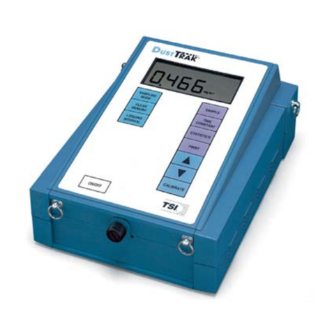
DataCan 109684 User manual

Portable Multi-Gauge Surface Box
DataCan User Manual –V1.1
PN: 109684
www.datacan.ca

Copyright 2022
Page 2 of
57
Table of Contents
TABLE OF CONTENTS................................................................................................................................................................ 2
1ABOUT THIS GUIDE .......................................................................................................................................................... 4
2INTRODUCTION................................................................................................................................................................. 5
3PRODUCT OVERVIEW...................................................................................................................................................... 6
3.1 PRODUCT DESCRIPTION .............................................................................................................................................. 6
3.1.1 USB Connection....................................................................................................................................9
3.1.2 Display On/Off Button........................................................................................................................9
3.1.3 Fuse............................................................................................................................................................9
3.1.4 Backup Clock Battery ..........................................................................................................................9
3.1.5 Main Internal Battery .......................................................................................................................10
3.2 PRODUCT SPECIFICATIONS.......................................................................................................................................... 6
3.3 NETWORK CONNECTIONS........................................................................................................................................... 7
3.4 COMPONENTS .............................................................................................................................................................. 8
4CONNECTING AND CONFIGURING SURFACE BOX WITH GAUGES ...........................................................11
4.1 TOOLS REQUIRED.......................................................................................................................................................11
4.2 CONNECTING GAUGES TO THE SURFACE BOX........................................................................................................12
4.3 INSTRUCTIONS FOR CONNECTING AND CONFIGURING ADDRESSABLE GAUGES ................................................14
4.4 INSTRUCTIONS FOR CONNECTING AND CONFIGURING NON-ADDRESSABLE GAUGES .....................................21
4.5 CONNECTING TO THE SURFACE GAUGES NETWORK..............................................................................................22
5BASIC SOFTWARE OPERATION..................................................................................................................................26
5.1 CONNECTING TO THE SURFACE BOX .......................................................................................................................26
5.2 DIAGNOSTICS..............................................................................................................................................................29
5.3 PROGRAMMING SAMPLE RATE.................................................................................................................................31
5.4 CHANGING UNITS ......................................................................................................................................................33
5.5 DOWNLOADING AND ERASING JOBS.......................................................................................................................35
5.6 GRAPHING DATA........................................................................................................................................................40
5.7 COMPANY NAME AND LOCATION ...........................................................................................................................42

Copyright 2022
Page 3 of
57
5.8 REAL-TIME DATA DISPLAY........................................................................................................................................44
6MODBUS-OUT NETWORK (SCADA).........................................................................................................................46
6.1 MODBUS-OUT COMMUNICATION SETTINGS .........................................................................................................46
6.2 CONNECTING TO THE MODBUS-OUT NETWORK...................................................................................................48
6.3 MODBUS-OUT REGISTER MAP.................................................................................................................................48
6.4 MODBUS DATA FORMAT ..........................................................................................................................................50
6.5 MODBUS TEST MODE AND MODBUS DEBUGGING................................................................................................51
7SCREEN WARNINGS AND ERRORS..........................................................................................................................52
8ADVANCED SURFACE BOX SETUP............................................................................................................................54
8.1 OUTPUT VOLTAGE......................................................................................................................................................54
8.2 POWER CYCLE TIMER.................................................................................................................................................55
8.3 SCREEN SETTINGS ......................................................................................................................................................56
9SURFACE BOX COMMISSIONING CHECKLIST .....................................................................................................57
History of Changes
Rev. No.
Date
Pages
Description of Changes
1.0
January 2021
47
Modified from V1.6 of Multigauge SRO
1.1
June 2022
59
Updated format, added specifications, reformatted
instructions, updated images, updated instructions

Copyright 2022
Page 4 of
57
1About This Guide
This document is intended as a supplement to formal training. DataCan is constantly working to
improve its products. We must therefore reserve the right to change designs, materials,
specifications and prices without notice. DataCan declines any liability that may arise out of the
potential inaccuracies in this guide.
This guide assumes that you have some computing and tool knowledge. For more information,
contact your local service representative.
www.datacan.ca
info@datacan.ca
We thank you for any feedback or comments that will help us to continue to improve our
products and service.
CONFIDENTIAL
This document and the proprietary information herein are the property of DataCan
Services Corp. It shall not be disclosed nor copied, in whole or in part, without the
written consent of DataCan Services Corp. Unauthorized transmission, reproduction,
transcription, or retrieval system storage in any form is prohibited.

Copyright 2022
Page 5 of
57
2Introduction
DataCan Services Corp. provides technology driven downhole measurement solutions that
deliver productivity, quality, and safety. We design, manufacture and service 200°C plus hybrid
platform instruments, patented multi-cycle instant close shut-in tools, reservoir management
systems and a suite of quartz and piezo-resistive pressure measurement instruments. We offer
specialized solutions that will help you improve productivity in your applications.
We are the leader in ultra-high temperature circuit design, manufacturing, and packaging.
•Our part selection process ensures the best long-term reliability is provided.
•Our fully automated surface mount assembly procedures ensure the highest quality
circuit is constructed every time with minimal heat impact.
•Our Hybrid design and construction techniques will enable DataCan and its customers to
reliably enter the 177ºC to 225ºC market.
•Our metal-to-metal seal and fully welded designs prevent potential leaks.
This manual is supplemented by several other manuals depending on the elements of your
system:
•DataCan Download Software User Manual –for all features of the software and graphing.
•Surface Transmitter Manual
•Multi-Gauge Telemetry Card Manual
•Cablehead Installation Manual
•Permanent Gauge Installation Manual
•Multi-Gauge Surface Box Troubleshooting Guide
To answer questions not covered in the manual about a specific component of your system,
please refer to the manual for that specific component.

Copyright 2022
Page 6 of
57
3Product Overview
3.1 Product Description
The DataCan Portable Surface Box is a reliable instrument that works in conjunction with
DataCan Downhole Gauges and Surface Gauges. In addition to providing power to the attached
equipment, the Surface Box displays the data collected; also, depending upon user settings, it
stores some of or all the collected information inside its on-board memory. A PC can be plugged
into the Surface Box to program which data is collected, displayed and recorded, as well as
download jobs from the memory using the included DataCan Download Software.
3.2 Product Specifications
NOTE: If your product is not one of the part numbers below, please contact a DataCan
representative to ensure this manual applies to your device.
Portable Surface Box
Description
Part No.
Multigauge Portable Surface Box
109684

Copyright 2022
Page 7 of
57
Specifications
Display
Pressure & Temperature
Memory Capacity
More Than 44 Million Samples
Download Via
USB, RS-485
Output
RS-485 Modbus RTU
Power In
AC Charger
Battery Life
Typical 7 days continuous operation on a full
charge for single gauge installation.
Accessories
Accessory Type
Part No.
USB-B Cable (6ft) [Included]
PE171UU0012
Surface Gauge Connector to 4 pin flywire
[Included] (Required to connect a telemetry
card to box)
111103
SCADA connector to 3 pin flywire [Included]
111108
DH Gauge Connector to Cablehead / Clips
[Included]
109805
DataCan Download Software (Free from the
website)
100872
3.3 Network Connections
The Surface Box connects to 3 different networks, as well as a USB link to a PC.
The 3 networks are:
-Modbus-Out network (SCADA connector)
-Downhole tool network (D.H. TOOL connector)
-Surface gauge network (S. GAUGE connector)
The Modbus-Out network is used to connect to a user’s SCADA system. The surface box has its
own configurable address for this network. Multiple surface boxes can be connected to the same
SCADA network.
The downhole network is used to collect data from DataCan Downhole Permanent Gauges or
Surface Readout Gauges. Up to 8 addressable gauges can be connected to the downhole tool
network or a single non-addressable gauge. Each gauge on the downhole tool network needs a
unique tool address. The address of a downhole tool is separate from any Modbus address.

Copyright 2022
Page 8 of
57
The surface gauge network is a Modbus network, separate from the Modbus-Out network that
the surface box can use to poll other Modbus sensors including other DataCan telemetry cards.
Each external Multi-Gauge Telemetry Card has its own downhole tool network. Each device
connected to the surface gauge network needs its own Modbus address on the network. This
can range from 1 to 247, with no two devices having the same address. The internal telemetry in
the Surface Box is address 0 (reserved). Addresses on this network are separate from the
Modbus-Out network, so devices on this network can have the same addresses as devices on the
user’s SCADA network..
3.4 Components
Your portable surface box may be made up of the following components.
1.Pelican Case
2.Display screen
3.USB cable input
4.Display on/off
5.Fuse holder and fuse
6.Power switch
7.Status indicator
8.SCADA connection
9.Surface Gauge connection
10. Downhole Gauge connection
11. Battery Charger Input
12. Clock back up coin cell (internal)
13. Lead acid batteries (internal)
14. Battery Charger (Not Shown)

Copyright 2022
Page 9 of
57
3.4.1 USB Connection
The USB connection is a standard USB type B socket. Any USB-B cable will connect to it.
Note: The USB connection will provide enough power to the unit to allow for memory download.
This is to allow for access to data even with a dead battery. However, the USB connection will not
run a gauge or recharge the battery.
3.4.2 Display On/Off Button
The green button on the front panel turns the screen off and on. To conserve power, the screen
is by default set to turn off after 1 minute. Refer to Screen Settings to change these settings.
3.4.3 Fuse
DataCan has installed a 1.8A 3AG slow blow fuse. If required, replace with identical component.
3.4.4 Backup Clock Battery
A coin cell is used as backup power to keep time and ensure samples are accurately
timestamped. Some units use a non-chargeable coin cell. If you see the following popup when
you connect the Surface Box to the DataCan Download Software, then your clock backup battery
is not functioning.
Note: The backup battery is located behind the screen and can only be accessed by removing
the screws around the edge of the edge of the faceplate. A battery saver tab may have to be
removed in new boxes. To replace the backup battery, use a new CR1632.

Copyright 2022
Page 10 of
57
3.4.5 Main Internal Battery
The portable SRO box contains two 9Ah sealed glass mat lead acid 12V batteries. These should
provide power for 6 days of continuous operation on a full charge.
Battery Charging
DataCan provides a 1A battery charger with the SRO box. To charge the batteries, simply connect
the provided charger to the 2 pin plug on the box and plug the charger into a standard AC wall
outlet. A discharged battery can take up to 20 hours to fully charge. The charger can be left
connected, and it will maintain a float charge that will not overcharge the batteries.
WARNING: Do not allow the batteries to drain below 10 V. It can damage the batteries and
reduce the battery life of your box.

Copyright 2022
Page 11 of
57
4Connecting and Configuring Surface Box
with Gauges
Proper installation of DataCan products ensures high-quality performance and long-lasting
results. The following section highlights the steps required to configure devices to the Surface
Box properly.
FOR MULTI-GAUGE SYSTEMS: The addresses of gauges in a multi-gauge system must be
configured so that each address is unique. The first time a set of gauges is connected, the
gauges must be connected to the system one at a time while the software is used to configure
the Telemetry Card and the gauge. After all gauges have been configured, they may be
connected all at once.
4.1 Tools Required
*If configuring multiple gauges
Ensure the battery is charged before starting an installation. See section Main Internal Battery for
more information about charging.
Description
Part No.
Portable surface box
109684
USB Download Cable
100682
Gauge to Surface Box Test Hookup Cable
109805
Passthru Gauge Test Hookup Cable (comes with passthru gauge for temporary
passthrough connection)*
109377
Windows laptop with DataCan Download Software Installed
N/A

Copyright 2022
Page 12 of
57
4.2 Connecting Gauges to the Surface Box
Warning: DO NOT have the Surface Box connected to a computer when powering it up or
down, it may damage the computer. Only connect the USB cable after the Surface Box has
been powered up.
1. Ensure the power switch is in the OFF position.
2. Before using the Multigauge Surface Box, the plastic tag on the card stack behind the
face plate must be removed. See section Backup Clock Battery
Note: The Battery must be replaced occasionally for the Surface Box to maintain time
during power outages.
Portable Box Switch

Copyright 2022
Page 13 of
57
3. Use the provided test cables to connect the Gauges to the Surface Box D.H. GAUGE
connector.
4. Switch the power switch to the ON position.
Note: The “DH TOOL COMM INDICATOR” will flash immediately to indicate power is on. If not,
confirm that your power supply is on, that you have connected the power lines to the correct
terminals, and that the fuse in the box is intact.
Note: When power is applied the screen should come on and display:
DataCan
Modbus logger
FW: YYYY Week: WW
Initializing….
If after 10 seconds any warnings have been displayed, see Section 6 –Screen Warnings and Errors
for a description of warnings and troubleshooting.

Copyright 2022
Page 14 of
57
If the surface box has already been configured the screen should be displaying pressure and
temperature readings of each gauge attached. If it is not displaying a reading for each gauge
attached or the readings are incorrect, proceed to the next section for configuring gauges and
surface boxes.
4.3 Instructions for Connecting and Configuring
Addressable Gauges
Note: These instructions are for addressable downhole gauges. For non-addressable downhole
gauges, see Section 4.4 –Instructions for Connecting and Configuring Non-Addressable Gauges.
1. Ten seconds after power-up, ensure that no warnings are being displayed on the screen.
See Section 6 –Screen Warnings and Errors for a description of warnings and
troubleshooting.
2. Connect Surface Box to DataCan Download Software via a USB cable.
Note: The Box draws minimal power from the USB if the main power supply is turned off. If you
want to power down the card, you must disconnect the USB cable.
Warning: DO NOT have the Surface Box connected to a computer when turning the box on
or off, it may damage the computer. Only connect the USB cable after the Surface Box has
been powered up.

Copyright 2022
Page 15 of
57
3. Open DataCan Download Software on your Windows PC. The startup page should
appear as shown below.
4. Press the Connect Button. See Section 5.1 –Connecting to the Surface Box for more
information about the Information screen and what happens when the Card connects.
Note: If configuring a multigauge system the sample rate should be set before configuring
gauges. The minimum sample rate for multi-gauge systems is 1 second per gauge. E.g. the
minimum for a 5 gauge system is 5 seconds. If you set the sample rate faster than that, the
system will sample at the best effort speed and the “tool current” diagnostic reading will be
affected. Setting the sample rate to 1 second even with a single gauge attached may affect the
“tool current” reading.

Copyright 2022
Page 16 of
57
5. If setting the sample rate click Program from the buttons in the top row, otherwise skip
to step 9.
6. Beside the Single Rate in Seconds, enter an appropriate sample rate. If the rate is
already appropriate there is no need to change anything.
7. If you have changed the sample rate, click on the Program Tool button found at the
bottom left of the screen. A pop-up window should appear with a message confirming
success.

Copyright 2022
Page 17 of
57
8. Click Information.
9. Enter Supervisor mode by pressing Ctrl+SHIFT+D at the same time. “-Supervisor
Mode” should appear in the top bar.
10. Once in Supervisor Mode, press the Edit button.
11. In the window that pops up, select “Multi Gauge” for addressable gauges, “Single
Gauge” is for non-addressable gauges. If buttons are not available, supervisor mode was
not entered, return to step 5. If there are any gauges listed that will not be connected to
this Telemetry Card, press the Remove button next to the corresponding gauge. With all
unneeded gauges removed, press the Update button.

Copyright 2022
Page 18 of
57
12. If needed, repress the Edit button once you have cleared the list of gauges. If needed,
reselect “Multi Gauge” in the reopened window. It will display the message “Gauge(s)
Not Configured…”.
13. To add gauges to the Surface Box list:
A) If connecting only once gauge to this Box, press the Discover button.
B) If multiple previously configured gauges are connected, press the Discover
button (This should be the case with installed gauges).
C) If connecting a set of multiple gauges together that have never been
configured:
a. Ensure only the gauge that is to be first in the list is attached.
b. Enter the Serial # of the gauge and press Add.
c. Once the first gauge has been added, connect the next gauge, enter
its Serial # and press Add.
d. Repeat for every gauge to be connected. The software will set the
address of each gauge in the order that they are added.

Copyright 2022
Page 19 of
57
Note: If multiple gauges with the same address are connected, communication errors
when adding the gauges may occur.
Note: Once a gauge has been added, it does not have to remain connected during the
rest of the configuration procedure.
14. Once a Gauge or Gauges have been detected and added, a window will appear
displaying the Gauge(s) connected.
15. If desired, labels can be applied to data that will be downloaded and appear on the
screen. This can be done for each Gauge in a Multi-Gauge or Single Gauge System.
Note: Labels can be edited at any time by pressing the Edit button.
16. When the configuration is complete, press the Update button.
Multi Gauge Window
Single Gauge Window

Copyright 2022
Page 20 of
57
17. If you have connected all devices for the system, and are going to use remote
monitoring, generate a Modbus map by clicking Utilities -> Generate Modbus Map
(PDF), and choosing a location and file name to save the PDF. If you have devices to
connect to the Surface Gauges network, wait until those are added to generate the map.
18. Connect all configured gauges and confirm the system is working through the
diagnostics screen by clicking Utilities -> Diagnostics. For full information on using the
diagnostics screen see section 5.2 –Diagnostics.
Data should also be flashing on the main display.
Note: If you have multiple devices connected to your Surface Box, the display screen will switch
between data from each device. By default, the display screen will automatically turn off after 1
minute. The green button on the side of the Surface Box or the grey button beside the power
switch of the Rackmount Unit turns the display screen on and off. To change the display screen
settings, refer to Screen Settings.
Table of contents
