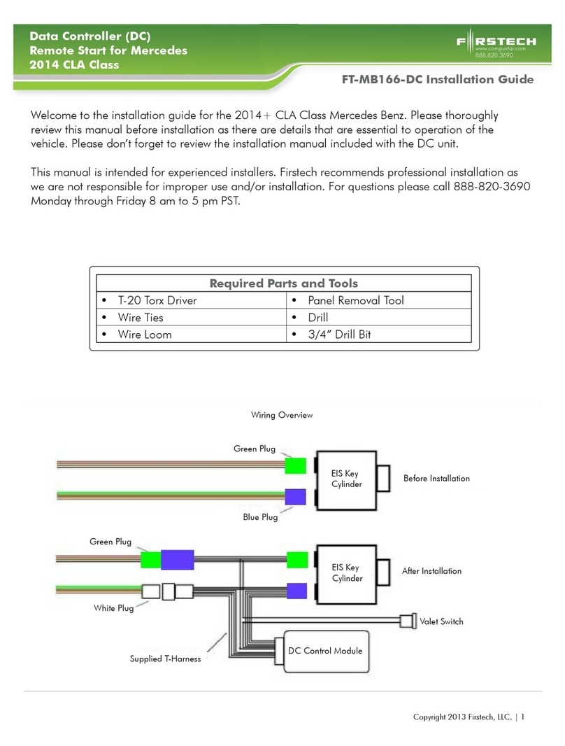
FT-MB211-DC Installation Guide
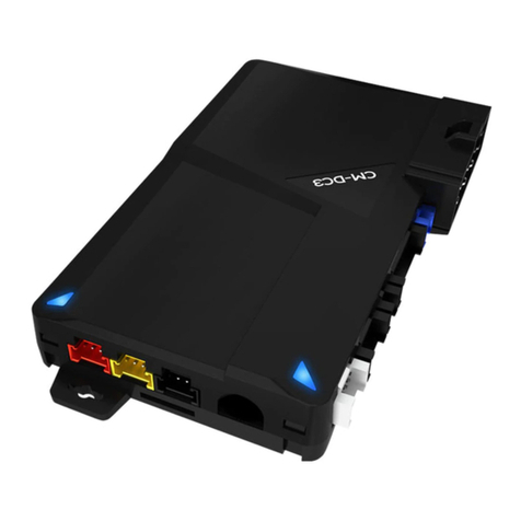
Data Controller (DC)
Remote Start for Mercedes
2004 - 2009 CLK Class
Copyright 2010 Firstech, LLC. | 2
www.compustar.com
888.820.3690
1. Make sure jumper is in the proper location prior to installation. See the general installation manual
for details.
2. Remove (3) T-20 screws from driver’s under dash panel and remove panel.
3. Remove (2) T-20 screws from driver’s knee bolster lower edge.
4. Using the panel removal tool, pry up on the shifter boot to release it.
5. Using the panel removal tool, pry up on the front corners of the shifter bezel and remove.
6. Using the flat blade or pick tool, release the clips from the ash tray, unclip wires and remove.
7. Remove (2) T-20 screws from the lower edge of the HVAC panel.
8. Using the panel removal tool, release the upper edge of the HVAC panel, disconnect wires and
remove.
9. Using the panel removal tool, pry out the lower side trim that was below the ash tray on either
side of the shifter.
10. Using the T-30 driver give a 1/2 counter clockwise turn to each of the cam lock screws below
the panels removed in step 8.
11. Using the panel removal tool, pry on either side of the switch panel above the radio, unclip
wires and remove.
12. Remove (4) T-20 screws from the radio, unclip wires and remove.
13. Slide open the center console cover and remove (2) T-20 screws from the rear of the opening.
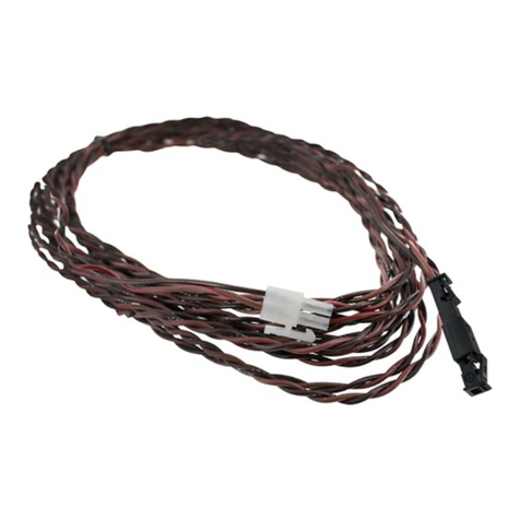
14. Remove the rubber liner from the bottom of the front cup holder to access and remove (1) T-20
screw. Pull cup holder out.
15. Remove (2) T-10 screws from the top rear of the cup holder opening.
16. Using the panel removal tool, pry up on the perimeter of the center console arm rest and lift up.
17. Remove (2) 10mm bolts from below the center console arm rest.
18. Remove (2) 10mm bolts from behind the shifter on either side.
19. The center console is now fully unbolted from the car. Slide it rearward as far as it will go.
20. Remove (3) T-20 screws from the left edge of the radio opening.
21. Using the small screwdriver or pick tool, release the clips that hold the gauge cluster in place
through the hole in each lower corner. Pull the cluster out, unclip the wires and remove.
22. Remove (2) T-20 from the upper edge of the knee bolster.
23. The knee bolster panel is now loose enough to be pulled away from the rest of the dashboard
to access the rear of the key cylinder.
24. Unclip and remove (2) plugs from the rear of the EIS. The EIS is the key cylinder.
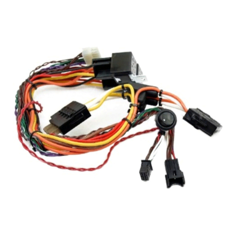
25. Plug the matching ends of the T-Harness into the rear of the EIS.
26. Plug the factory EIS harness into the other end of the T-Harness.
27. Once ALL connections are secured, turn on the valet switch and verify the LEDs visible inside
the Mercedes DC are flashing.
28. Start the vehicle with the key to verify your work. If the vehicle starts and runs, you’ve made all
the connections correctly.
29. Shut the vehicle off.
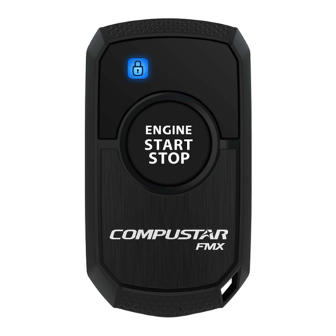
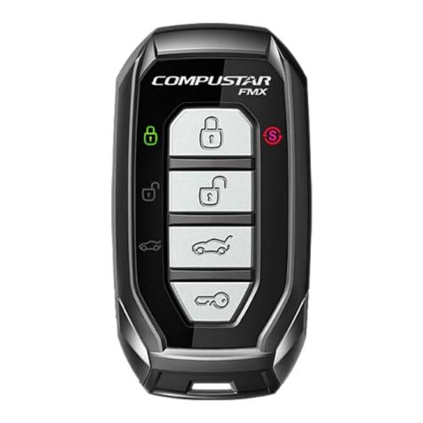
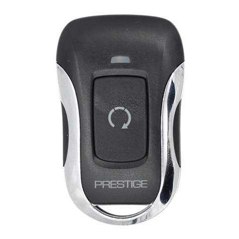
30. Push the ‘Panic’ button once on the remote to test the remote starter.
Instructions

