Datalogic PWR-120 User manual

PWR-120
INSTALLATION MANUAL
Reading Station Power Supply

Datalogic S.r.l.
Via S. Vitalino, 13
40012 Calderara di Reno (BO)
Italy
Tel. +39 051 3147011
Fax +39 051 3147205
© 2016-2020 Datalogic S.p.A. and /or its affiliates
All rights reserved. Without limiting the rights under copyright, no part of this documentation may be repro-
duced, stored in or introduced into a retrieval system, or transmitted in any form or by any means, or for any
purpose, without the express written permission of Datalogic S.p.A. and/or its affiliates.
Owners of Datalogic products are hereby granted a non-exclusive, revocable license to reproduce and
transmit this documentation for the purchaser's own internal business purposes. Purchaser shall not
remove or alter any proprietary notices, including copyright notices, contained in this documentation and
shall ensure that all notices appear on any reproductions of the documentation.
Electronic versions of this document may be downloaded from the Datalogic website (www.datalogic.com).
If you visit our website and would like to make comments or suggestions about this or other Datalogic pub-
lications, please let us know via the "Contact" page.
Disclaimer
Datalogic has taken reasonable measures to provide information in this manual that is complete and accu-
rate, however, Datalogic shall not be liable for technical or editorial errors or omissions contained herein,
nor for incidental or consequential damages resulting from the use of this material. Datalogic reserves the
right to change any specification at any time without prior notice.
Trademarks
Datalogic and the Datalogic logo are registered trademarks of Datalogic S.p.A. in many countries, including
the U.S.A. and the E.U.
Matrix 450N and XRF410N are trademarks of Datalogic S.p.A. and/or its affiliates. All other trademarks and
brands are property of their respective owners.
Patents
See www.patents.datalogic.com for patent list.

INSTALLATION MANUAL
iii
TABLE OF CONTENTS
PREFACE ..................................................................................................................IV
About this Manual ........................................................................................................... iv
Manual Conventions ........................................................................................................................... iv
Safety REGULATIONS ..................................................................................................... iv
Electrical Safety .................................................................................................................................. iv
Product Data Label .............................................................................................................................. v
Technical Support ............................................................................................................ v
Support Through the Website ............................................................................................................. v
Reseller Technical Support ................................................................................................................. v
CE Compliance ..................................................................................................................................... v
Warning ............................................................................................................................................... v
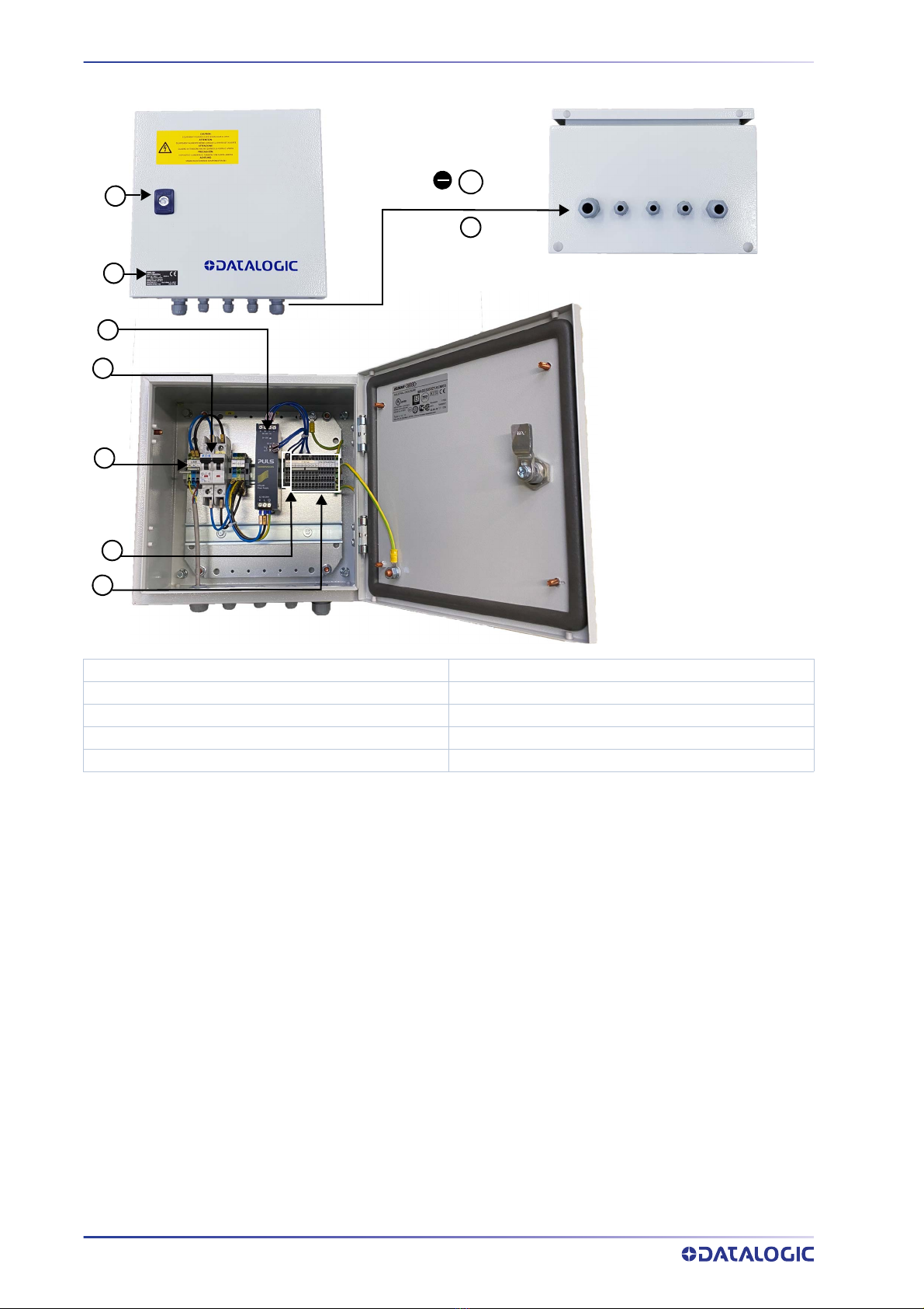
General View .................................................................................................................. vi
CHAPTER 1.
OPERATING FEATURES ......................................................................... 1
Description ...................................................................................................................... 1
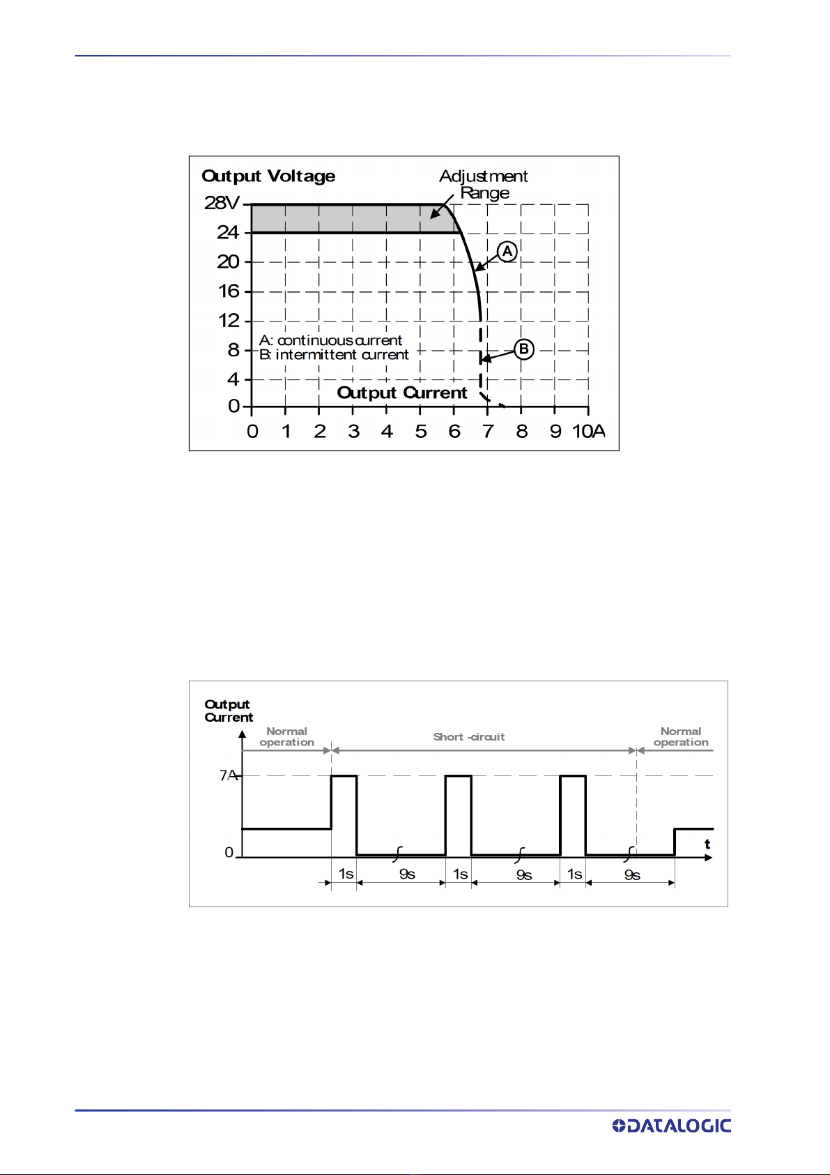
Output Protection ............................................................................................................. 1
Light Overload .....................................................................................................................................2
Heavy Overload (including short-circuit) ...........................................................................................2
CHAPTER 2.
PRE-INSTALLATION CHECKLIST ........................................................... 3
System Wiring: DC Output ................................................................................................ 3
System Wiring: AC Input .................................................................................................. 3
System Wiring: Test ......................................................................................................... 4
CHAPTER 3.
MECHANICAL INSTALLATION................................................................5
Cabinet Mounting ............................................................................................................. 5
CHAPTER 4.
LOW VOLTAGE ELECTRICAL CONNECTIONS........................................... 6
DC Low Voltage Cable insertion ........................................................................................ 6
Compression Connectors ...................................................................................................................6
Installing the AS-I Cable ......................................................................................................................7
DC Voltage Terminal Block ............................................................................................... 8
DC OK Monitoring ................................................................................................................................8
DC Direct Output ..................................................................................................................................8
Laser Barcode Scanners ................................................................................................... 9
Supply Capacity When Wiring Directly to AS-I Compatible Scanners ..............................................9
Image-Based id Readers ................................................................................................ 10
Supply Capacity When Wiring to XRF410N Readers .......................................................................10
Supply Capacity When Wiring to Matrix 450N Readers ...................................................................12
CHAPTER 5.
AC LINE VOLTAGE ELECTRICAL CONNECTIONS ................................... 13
AC Line Input Voltage ..................................................................................................... 13
CHAPTER 6.
TECHNICAL FEATURES ....................................................................... 15
APPENDIX A.
ELECTRICAL DIAGRAMS ................................................................... 16
PWR-120 Electrical Diagram .......................................................................................... 16

iv
PWR-120
PREFACE
ABOUT THIS MANUAL
This Instruction Manual is provided for users seeking advanced technical information,
including installation, connections, maintenance and specifications.
Manual Conventions
The following conventions are used in this document:
The symbols listed below are used in this manual to notify the reader of key issues or
procedures that must be observed when using the reading station power supply:
SAFETY REGULATIONS
Electrical Safety
This product conforms to the applicable requirements contained in the following Euro-
pean Standards:
• EN 61439-1
• EN 60204-1
• EN 60950-1 +A11 +A1 +A12 +A2
• EN 62368-1
NOTE: Contains important information necessary for proper installation
and use of the device.
The CAUTION symbol advises you of actions that could damage equipment
or property.
HIGH VOLTAGE: This symbol alerts the user they are about to perform an
action involving, either a dangerous level of voltage, or to warn against an
action that could result in damage to devices or electrical shock. Opera-
tions having this symbol must be performed by qualified personnel only.

TECHNICAL SUPPORT
INSTALLATION MANUAL
v
Product Data Label
The Product data label is located on the outside door panel.
Figure 1 - Product Data Label
TECHNICAL SUPPORT
Support Through the Website
Datalogic provides several services as well as technical support through its website. Log
on to (www.datalogic.com).
For quick access, from the home page click on the search icon , and type in the name of
the product you’re looking for. This allows you access to download Data Sheets, Manu-
als, Software & Utilities, and Drawings.
Hover over the Support & Service menu for access to Services and Technical Support.
Reseller Technical Support
An excellent source for technical assistance and information is an authorized Datalogic
reseller. A reseller is acquainted with specific types of businesses, application software,
and computer systems and can provide individualized assistance.
CE Compliance
CE marking states the compliance of the product with essential requirements listed in
the applicable European directive. Since the directives and applicable standards are
subject to continuous updates, and since Datalogic promptly adopts these updates,
therefore the EU declaration of conformity is a living document. The EU declaration of
conformity is available for competent authorities and customers through Datalogic
commercial reference contacts. Since April 20th, 2016 the main European directives
applicable to Datalogic products require inclusion of an adequate analysis and assess-
ment of the risk(s). This evaluation was carried out in relation to the applicable points of
the standards listed in the Declaration of Conformity. Datalogic products are mainly
designed for integration purposes into more complex systems. For this reason, it is
under the responsibility of the system integrator to do a new risk assessment regarding
the final installation.
Warning
This is a Class A product. In a domestic environment this product may cause radio inter-
ference in which case the user may be required to take adequate measures.

PREFACE
vi
PWR-120
GENERAL VIEW
Figure 2 - PWR-120 General View
1) Key Lock 5) Thermal-Magnetic Circuit Breaker
2) Product Data Label 6)AC Line Input Terminal Block
3) Compression Connectors 7) “DC OK” Terminal Block
3a) AS-I Cable Sealing Grommet 8) 24 Vdc Terminal Block
4) Monophase Switching Power Supply
4
5
6
7
8
1
2
3
3a

INSTALLATION MANUAL
1
CHAPTER 1
OPERATING FEATURES
DESCRIPTION
The PWR-120 is an electrical cabinet housing a 24 Vdc power supply which is used to
power up a varying number of reading devices (depending on the product), along with
their relative accessory devices. See “LOW Voltage Electrical Connections” on page 6 for
details.
As shown in Appendix Electrical diagrams the AC Input Line passes through a protective
thermo-magnetic circuit breaker and connects to the monophase switching power sup-
ply.
The 24 Vdc output power is connected to the output terminal blocks which are pro-
tected by the internal power supply features.
Two output power supply status monitoring signals (DC-OK) are provided to connect to
an optional digital alarm. If for some reason the output voltage is reduced by less than
90% of nominal, these lines open.
OUTPUT PROTECTION
This power supply is specifically designed to power Datalogic devices and implements
output protection according to the type of overload behavior.

OPERATING FEATURES
2
PWR-120
Light Overload
Light Overload is defined as application of a load that results in a reduction of the out-
put voltage that remains above 13V. In this case the power supply can deliver up to 7.2
amperes continuously. See Figure 1 on page 2 (A: continuous current)
Figure 1 - Overload Behavior
Heavy Overload (including short-circuit)
Heavy Overload is defined as application of a load which causes a reduction in voltage
below 13V. This causes the power supply to enter HICCUP operation where power is
supplied for 1 second and then shuts off for 9 seconds. This procedure is repeated until
the short-circuit or overload is resolved, see Figure 4 Short-Circuit Protection HICCUP
Mode. For this condition, the maximum length of the power cables between the power
supply and the powered devices guarantees the behavior of a short-circuit downstream
of this cable.
Figure 2 - Short Circuit Protection HICCUP Mode

INSTALLATION MANUAL
3
CHAPTER 2
PRE-INSTALLATION CHECKLIST
This chapter can be used as a checklist to verify all the steps necessary to complete
installation of the PWR power Supply.
1. Read all information in this manual before installation, paying particular attention
to all Caution and Warning notes.
2. Mount the PWR to the Station frame using the brackets and bolts provided in the
package. See “Cabinet Mounting” on page 5.
SYSTEM WIRING: DC OUTPUT
3. Connect your devices in the PWR according to your application.
Barcode Scanners
Correctly connect the AS-I cabling to the PWR using the AS-I cable wiring instruc-
tions for backbone and branch wiring. See “Laser Barcode Scanners” on page 9.
and your scanner manual for details. All cables must pass through the compres-
sion connector as described in See “DC Low Voltage Cable insertion” on page 6.
Image Based ID Readers
Connect your specific product as described in the sub-paragraph under Chapter 4,
Image-Based id Readers and the reader manual. All cables must pass through the
compression connector as described. See “DC Low Voltage Cable insertion” on
page 6.
SYSTEM WIRING: AC INPUT
4. To comply with EN60950-1:2007 par.1.7.2.2, par. 2.7.1, par 2.7.4, par. 3.4.6, and to
protect the AC input connection to the device; a disconnecting device with built in
overcurrent and earth protection shall be installed external to the equipment
according to local regulations.
According to EN60950-1:2007 par. 3.2.3; the AC input cable must have a maximum
diameter of 14mm and the conduit a max diameter of 16mm.
5. With AC line voltage OFF, wire the AC Line to the AC Line Input Terminal Block. See
“AC Line Input Voltage” on page 13.
HIGH VOLTAGE: Opening the cabinet requires a key that should be used by a
person adequately advised or supervised by an electrically skilled person
to enable him or her to perceive risks and avoid hazards which electricity
can create. Internal components guarantee an IP20 degree of protection
against direct contact.

PRE-INSTALLATION CHECKLIST
4
PWR-120
SYSTEM WIRING: TEST
6. Apply the AC line voltage from the building installation or the DWS-SWITCH and
check that the PWR powers up correctly. The green DC-OK light should be on
steady and the overload light (red) should off.
7. Close and lock the PWR enclosure and check that it does not open (lock functions
correctly).
The PWR-120 installation is now complete.

INSTALLATION MANUAL
5
CHAPTER 3
MECHANICAL INSTALLATION
CABINET MOUNTING
The cabinet must be mounted to the reading station frame using the brackets and bolts
provided in the package.
1. Mount the bracket to the cabinet.
2. Mount the cabinet to the frame.
Figure 1 - Mounting Brackets
Figure 2 - PWR-120 cabinet max. height
Please note that the cabinet door can be unlocked and opened by using the key pro-
vided along with the product.
NOTE
The cabinet must be installed vertically in such a way that the key lock is
not higher than 1.90 m from the ground.
max. 190 cm

6
PWR-120
CHAPTER 4
LOW VOLTAGE ELECTRICAL
CONNECTIONS
DC LOW VOLTAGE CABLE INSERTION
The compression connectors have IP65 protection capability. All cables must pass
through the compression connectors.
Compression Connectors
Follow these instructions to correctly insert the cables:
1. Determine the number and size of the cables coming into and leaving the PWR-
120.
2. Locate the correct compression connector sizes and positions relative to these
cables.
3. Pass the cable end through the proper compression connector so that the gland
material seals around it when tightened.
There are three compression connector sizes with the following specifications:
NUMBER OF
COMPRESSION
CONNECTORS
CABLE DIAMETER
Millimeters Inches
1 9-14 0.354-0.551
3 3.5-8 0.138-0.315
1 7-13 0.256-0.512

DC LOW VOLTAGE CABLE INSERTION
INSTALLATION MANUAL
7
Installing the AS-I Cable
Prepare the AS-I cable by first inserting the compression connector nut, then the AS-I
cable sealing grommet onto the AS-I cable. Then strip the outer protection sheath leav-
ing about 5 cm of blue and brown wires free for positioning. Strip the individual wires
for insertion into the Terminal Block.
Pass the AS-I cable through the compression connector and make sure there is enough
length to easily reach the 24 Vdc Terminal Block.
Seat the AS-I cable sealing grommet into the compression connector and tighten the
compression connector nut.
Figure 1 - Cable insertion
AS-I Cable

LOW VOLTAGE ELECTRICAL CONNECTIONS
8
PWR-120
DC VOLTAGE TERMINAL BLOCK
Figure 2 - PWR-120 DC Output Power Connections
DC OK Monitoring
The DC voltage terminal block provides two wiring terminals (13-14), which monitor the
status of the switching power supply (DC OK feature). When the power supply module
runs correctly, lines 13 and 14 form a normally closed contact. If the power module
experiences problems (i.e. output overload causing output voltage to be reduced by less
than 90% of nominal) these lines open. Lines 13 and 14 are decoupled from the power
output lines and can be connected to a free digital input to signal this alarm condition.
DC Direct Output
The 24 volt DC Output terminals allow direct connection to your devices according to
your application requirements.
DC OK Signals
DC Outputs

LASER BARCODE SCANNERS
INSTALLATION MANUAL
9
LASER BARCODE SCANNERS
Supply Capacity When Wiring Directly to AS-I Compatible Scanners
For direct wiring, power distribution is performed simultaneously for all the scanners.
However all the scanner motors start up slowly so that there is no significant peak cur-
rent draw. See the specific scanner manual for consumption data.
The maximum number of same type scanners to be supplied for direct wiring by a single
PWR-120 is shown in the table below:
The following products are also AS-I compatible: DS5100, DM3610, SC5000. In case of
networks using a mix of products, you must calculate the total power consumption so as
not to exceed the power limits. See the specific product reference manual in the Techni-
cal Features chapter for consumption data.
The power supply unit is connected directly to the scanners via AS-I cabling.
Figure 3 - Connecting PWR-120 to AS-I Compatible Scanners
Refer to the specific scanner manual for I/O interface wiring connections.
SCANNER TYPE MAXIMUM NUMBER OF
SCANNERS
Single Branch
DS8110 6
DX8210 6
AC in
24 Vdc to scanners using AS-I cabing with end cap

LOW VOLTAGE ELECTRICAL CONNECTIONS
10
PWR-120
IMAGE-BASED ID READERS
Supply Capacity When Wiring to XRF410N Readers
The maximum number of XRF410N modules to be supplied by a single PWR-120 is
shown in the following table.
The power supply unit is connected to the XRF410N Base module through the CBX500
AATS-001 according to the following example diagram:
Figure 4 - Connecting PWR-120 to XRF410N Base Modules
XRF410N MODEL MAXIMUM NUMBER OF
MODULES
Base (Bxx) 2
Hi Perf (Hxx) 1
CUSTOM POWER CABLE TO CBX
PWR-120 CBX
24 V+ Vdc
0 V- GND
AC in
24 Vdc
Custom cable
CBX ATS-001
CAB-DS05-S
CBL-1480-05
XRF410N Master
ID-NETTM
Terminator applied
to last module in
chain
Ethernet Host
P. S .

IMAGE-BASED ID READERS
INSTALLATION MANUAL
11
The power supply unit is connected to the XRF410N Hi Perf module through the CBX500
ATS-001 according to the following example diagram. In this case separate power con-
nection is also supplied to the QL connector for Illuminator power.
Figure 5 - Connecting PWR-120 to an XRF410N Hi Perf Module
CUSTOM POWER CABLE TO
CBX CAB-MLP-0X CABLE
PWR-120 CBX Wire Color Meaning
24 V+ Vdc White 24 V+
0 V- GND Blue 0 V-
AC in
Custom cable
24 Vdc CAB-MLP-05
CBL-1480-05
P. S .
Ethernet Host
CBX500 ATS-001
CAB-DS05-S
XRF410N
Master
ID NETTM
Terminator

LOW VOLTAGE ELECTRICAL CONNECTIONS
12
PWR-120
Supply Capacity When Wiring to Matrix 450N Readers
One PWR-120 is able to power in parallel:
• one Matrix 450N + LT-03x illuminator
• one CBX connection box with all the standard sensors
The power supply unit can be connected to the Matrix 450N readers according to the
following example diagram:
Figure 6 - Connecting PWR-120 to a Matrix 450N
CUSTOM POWER CABLE TO
CBX CAB-LP-0X CABLE TO LT-03X
PWR-120 CBX Wire Color Meaning
24 V+ Vdc Brown/White 24 V+
0 V- GND Black/Blue 0 V-
AC in CAB-LP-0x
24 Vdc
Custom Cable
Ethernet Host
CBX
CAB-MS0x
PS
The Matrix 450N uses the
CAB-LD-102 no power
cable between the reader
and its relative LT-03x illu-
minator.

INSTALLATION MANUAL
13
CHAPTER 5
AC LINE VOLTAGE ELECTRICAL
CONNECTIONS
AC LINE INPUT VOLTAGE
Wire according to the following points:
Primary wiring: Overcurrent protection should be provided by a 16 A building installa-
tion circuit breaker. PWR-120 input components are rated for an Icp of 10 kA max.
Wiring methods from the branch circuit breaker to the PWR-120 power supply shall
comply with the National Electric Code ANSI\NFPA. The Datalogic DWS-SWITCH is an AC
Power Disconnector and Distributor cabinet which provides this protection.
For primary wiring use a 3-conductor cable (between 2.5 mm2 - 4 mm2 (13 AWG - 11
AWG), for every conductor. Choose the overall cable diameter and UL Listed conduits
accordingly. The AC input cable must be inserted through the AC Input Cable Compres-
sion Connector.
The individual conductors must be inserted into the dedicated terminal blocks on the
DIN rail (see figure below) which are marked Line (L) neutral (N) and Protection Earth
(PE).
HIGH VOLTAGE: This operation must be performed by a certified electrician.

AC LINE VOLTAGE ELECTRICAL CONNECTIONS
14
PWR-120
Replace the protection cover over the spring clamp connector after correctly installing
the wires.
Figure 1 - PWR-120 AC Line Terminal Block with Protection Covers
AC Line
terminal block
Protection covers
Other manuals for PWR-120
2
Table of contents
Other Datalogic Power Supply manuals