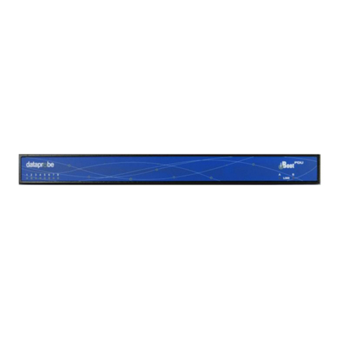
Dataprobe iBoot-Exp User manual

Expansion
Module for iBoot
1.General Description
The iBoot-Exp is a remote controlled power On / Off
switch. It is designed to be controlled by
Dataprobe’s iBoot-G2+ Web Enabled Power Switch,
as an expansion unit.
iBoot-Exp handles worldwide power from 105-
240VAC. It is capable of switching up to 12 Amps
at 120VAC and 10 Amps at 220 VAC.
Two iBoot-Exp units can be connected and
independently controlled by the iBoot-G2+. For
complete information, refer to the documentation for
the iBoot-G2+.
2.Connections
2.1. Connect iBoot-G2+
iBoot-G2+ has two Expansion Ports, Exp1 and Exp2 for connection to iBoot-Exp, Connections to the iBoot-Exp are
made using screw terminal blocks.
The screw terminal blocks are on removable connectors for easy cable fabrication. A suitable cable is supplied with
the iBoot-EXP. See Specification below for additional connection information.
iBoot-G2+ iBoot-Exp Function
V+ +12 Volts Out V+ +12 Volts In Power. iBoot-G2 to iBoot-Exp
I Control Input O Control Output Status. iBoot-Exp to iBoot-G2+
G Ground G Ground Common Ground
O Control Output I Control Input Control. iBoot-G2+ to iBoot-Exp
Fig. 1 iBoot Expansion
Fig. 2 iBoot Expansion Wiring

2.2. Connect Powered Device
Connect the device to be powered ON and OFF to the IEC receptacle
marked Switched Outlet. An IEC 320 to North American (NEMA 5-15)
power cord is included for connecting the iBoot-G2 outlet to the device
to be controlled.
Make sure that the combined load of all controlled
devices does not exceed 12 Amps for 105-125VAC or 10
Amps for 210-240VAC.
2.3. Connect Power Mains
Connect the supplied power cord to the connector labeled AC Input, and
the other end to your AC source. If a power cord with a different terminating plug is required, be sure it is properly
rated and meets all the required local electrical standards. Fig. 3 Connect
Powered Device
Fig. 4 Connect
Power Mains Fig. 5 Other Power Cords
Sourced Locally
3.LED Indicators
The iBoot-EXP had two LED indicators.
LED OFF ON
OK - Green No Power Connection from iBoot-G2+ or 12VDC
source. The PWR LED is not indicative of the
Power outlet status
Power to drive the iBoot-EXP is connected.
PWR - Red When OK LED ON = Power OFF to the Outlet
When OK LED OFF = Not Valid Indication of
Power OFF. Power to the outlet may be ON.
Power Outlet On
V100921e iBoot-EXP Page 2

V100921e iBoot-EXP Page 3
4.Mounting Options
iBoot-G2+ is suitable for desktop or shelf mounting. A mounting
kit for wall and DIN rail mounting is available. Order part:
1920033 Mounting Kit for iBoot-G2+ G2 Series
Remove all cables from the unit prior to installing or
removing any mounting hardware.
4.1.1. Installing the Wall Mounting Kit 4.1.2. DIN Rail Mounting
1. Remove the
four mounting
screws from
the underside
of the unit.
Do not
disassemble
the unit.
1. Install the
Wall
Mounting Kit
as shown.
2. Install the wall
mounting ears
to the unit
using the
screws
removed in
Step 2
2. Install the
DIN rail clips
using the
four screws
provided.
3. The unit is
ready for wall
mounting.
3. Ready for
DIN rail
mounting.
4. Use M3 or #4
screws (not
included) for
attachment to
suitable
surface
1920033 Mounting Kit
iBoot G2 Series

V100921e iBoot-EXP
5.Specifications
5.1. Physical
Height
2.0” 60mm
Page 4
Width 3.2” 82mm
Depth 4.2” 107mm
Weight 8.6 oz 244g
MTBF 540,000 Hours
Temperature 0 – 50 degrees C
5.2. AC
Input IEC 320 C14
Input Cord 16AW 0
UL/CSA/VDE Rated
(1.25m
GX3C 10A 25
m2X3C)
Voltage Range Auto S 40 VACensing 105-2
Switched IEC 3
Receptacle 20 C13
Capacity 12 A Max at 105-125 VAC,
10 A Max at 210-240 VAC
5.3.
Power and Control Connections
Four position removable screw terminals.
18AWG maximum.
Maximum distance to iBoot-G2+
330feet/100m using 24AWG wire.
+V External + 12VDC input provided by
iBoot G2+
I Control Input. Contact closure or open
collector transistor circuit only
O Status feedback. Open collector circuit.
PowerOpen = Power On, Grounded =
Off
5
File No. 188
.4. Compliance
UL/cUL UL60950 Listed I.T.E
CE Di
93
E
E
rectives 89/336/EEC, 92/31/EEC and
/68/EEC
N 60950: 3rd Edition
N 55022: 1998 Class B
FCC Part 15 Class B
6.Important Safety Instructions
When using
persons, incl
this produ precautions should always be followed to r tric shock, and injury to
uding the following:
understand all in
2. Follow all warnings and ma
3. Unplug this product from the w liquid cleaners
or aerosol cleaners. Use a damp cloth for cleaning.
4. Do not use this product in an outdoor environment or near water, for example, near a
bath tub, wash bowl, kitchen sink, or laundry tub, in a wet basement, or near a
swimming pool.
5. Do not place this product on an unstable cart, stand, or table. The product may fall,
causing serious damage to the product.
6. Slots and openings in this product and the back or bottom are provided for ventilation
to protect it from overheating; t
openings should never be blocke
other similar surface. This prod
heat register. This product shoul
ventilation is provided.
rounding type plug, a plug having a third
(grounding) pin. This plug will only fit into a grounding type power outlet. This is a
rt the plug into the outlet, contact your
efeat the safety purpose of the
1 t overloa n cords as this can result in the risk of fire or
electric shock.
11. Never push objects of any kind into this product through slots as they may touch
dangerous voltage points or short out parts that could result in a risk of fire or
electrical shock. Never spill liquid of any kind on the product.
12. To reduce the risk of electrical shock, do not disassemble this product, but take it to a
qualified serviceman when some service or repair work is required. Opening or
removing covers may expose you to dangerous voltages or other risks. Incorrect re-
assembly can cause electric shock when the appliance is subsequently used.
13. Unplug this product from the wall outlet and refer servicing to qualified service
conditions:
cord or plug is damaged or frayed.
into the product.
exposed to rain or water.
d) If the product does not operate normally by following the operating instructions.
often require extensive work by a qualified technician to restore the product to
normal operation.
15.
ct, basic safety educe the risk of fire, elec
1. Read and structions.
rked on the product.
all outlet before cleaning. Do not use
0. Do no d wall outlets and extensio
hese openings must not be blocked or covered. The
d by placing the product on the bed, sofa, rug, or
uct should never be placed near or over a radiator or
d not be placed in a built-in installation unless proper
personnel under the following
a) When the power supply
b) If liquid has been spilled
c) If the product has been
7. This product should be operated only from the type of power source indicated on the
marking label. If you are not sure of the type of power supply to your home, consult
your dealer or local power company.
. This product is equipped with a three wire g
Adjust only those controls that are covered by the operating instructions
because improper adjustment of other controls may result in damage and will
8e) If the product has been dropped or has been damaged.
f) If the product exhibits a distinct change in performance.
safety feature. If you are unable to inse
electrician to replace your obsolete outlet. Do not d 14. Avoid using a telephone (other than a cordless type) during an electrical storm.
There may be a remote risk of electric shock from lightning.
Do not use the telephone to report a gas leak in the vicinity of the leak.
grounding type plug. Do not use a 3-to-2 prong adapter at the receptacle; use of this
type adapter may result in risk of electrical shock and/or damage to this product.
9. Do not allow anything to rest on the power cord. Do not locate this product where the
cord will be abused by persons walking on it. 16. Do not exceed the maximum output rating of the auxiliary power receptacle
Save These Instructions

ort and Warranty7.Technical Supp
Da 5:30PM ET to assist you in the installation and operation of this
prod 5111, or Email us at tech@dataprobe.com. Please have the
follow :
•
•
•
• be)
If rized Dataprobe Reseller, you should contact them first, as
they may have information about the application that can more quickly answer your questions.
7.1. WARRANTY
Seller warrants this product, if used in accordance with all applicable instructions, to be free from original defects in
material and workmanship for a period of One Year from the date of initial purchase. If the product should prove
defective within that period, Seller will repair or replace the product, at its sole discretion.
Service under this Warranty is obtained by shipping the product (with all charges prepaid) to an authorized service
center. Seller will pay return shipping charges. Call Dataprobe Technical Service at (201) 934-5111 to receive a
Return Materials Authorization (RMA) Number prior to sending any equipment back for repair. Include all cables,
power supplies and proof of purchase with shipment.
THIS WARRANTY DOES NOT APPLY TO NORMAL WEAR OR TO DAMAGE RESULTING FROM ACCIDENT,
MISUSE, ABUSE OR NEGLECT. SELLER MAKES NO EXPRESS WARRANTIES OTHER THAN THE WARRANTY
EXPRESSLY SET FORTH HEREIN. EXCEPT TO THE EXTENT PROHIBITED BY LAW, ALL IMPLIED
WARRANTIES, INCLUDING ALL WARRANTIES OF MERCHANT ABILITY OR FITNESS FOR ANY PURPOSE ARE
LIMITED TO THE WARRANTY PERIOD SET FORTH ABOVE; AND THIS WARRANTY EXPRESSLY EXCLUDES
ALL INCIDENTAL AND CONSEQUENTIAL DAMAGES.
Some states do not allow limitations on how long an implied warranty lasts, and some states do not allow the
exclusion or limitation of incidental or consequential damages, so the above limitations or exclusions may not apply to
you. This warranty gives you specific legal rights, and you may have other rights which vary from jurisdictions to
jurisdiction.
WARNING: The individual user should take care to determine prior to use whether this device is suitable, adequate or
safe for the use intended. Since individual applications are subject to great variation, the manufacturer makes no
representation or warranty as to the suitability of fitness for any specific application.
Dataprobe Inc.
tauct. To obtain Technical Support call 201- 934-
probe Technical Support is available 8:30AM to
ing information available when you call
Model of Product
Lot and Version Numbers
Data of Purchase
Name of Seller (if other than Datapro
you purchased this product through an Autho
Table of contents
Other Dataprobe Computer Hardware manuals
Popular Computer Hardware manuals by other brands
Anycom
Anycom CF-300 Technical note

CTC Parker Automation
CTC Parker Automation PowerStation P1 user guide
Fenwal Controls
Fenwal Controls 35-53CE Series quick start guide
Avid Technology
Avid Technology Pinnacle PCTV DVB-T user guide
NXP Semiconductors
NXP Semiconductors winbond MCX-N9 BRK Series quick start guide
dbx
dbx 286 S user manual
